Sign In
Upload
Manuals
Brands
Phoenix Contact Manuals
Controller
AXC 3050
User Manuals: Phoenix Contact AXC 3050 PLC Controller
Manuals and User Guides for Phoenix Contact AXC 3050 PLC Controller. We have
1
Phoenix Contact AXC 3050 PLC Controller manual available for free PDF download: User Manual
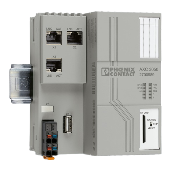
Phoenix Contact AXC 3050 User Manual (146 pages)
Brand:
Phoenix Contact
| Category:
Controller
| Size: 3 MB
Table of Contents
Table of Contents
5
1 Foreword
9
Purpose of this User Manual
9
Hardware and Software Requirements
9
Parameterization Memory, Plug-In
9
2 Description of the AXC 3050 Controller
11
General Description of the Controller
11
Components of the Controller
11
Possible Fields of Application of the AXC 3050
14
Axioline F Station with AXC 3050 Controller
14
The AXC 3050 as a Distributed Controller of an Axioline F Station
14
AXC 3050 as a PROFINET Controller
15
The AXC 3050 as a PROFINET Controller in a PROFINET Network
15
PROFINET Device Using the AXC 3050 as an Example
16
System Redundancy with AXC 3050
16
The AXC 3050 as a PROFINET Device in a PROFINET Network
16
Redundant Higher-Level Control System
17
Unpacking the AXC 3050 Controller
18
Connection and Operating Elements
19
Reset Button
19
Structure of the Controller
19
Diagnostics and Status Indicators
20
Diagnostics and Status Indicators of the Controller
21
Mode Selector Switch
24
Controller Operating Modes
25
Reset Button (Concealed)
26
Parameterization Memory
26
Internal Basic Circuit Diagram
28
Internal Basic Circuit Diagram (AXC 3050)
28
Power Supply
28
Interfaces
29
Communication Paths
29
Communication Paths: (1) Ethernet, (2) USB
29
Connecting the Ethernet Cable to the Controller
30
Ethernet
30
Ethernet Interface and Pin Assignment
30
Connecting Cable between PC and AXC 3050
31
USB Interface (USB A)
32
Connection for the Supply Voltage
32
USB Interface (X6)
32
Bus Base Module
33
Structure of the Bus Base Module
33
3 Mounting/Removal and Power Supply
35
Basic Information about Mounting
35
End Brackets
36
Mounting Location
36
Mounting Position
36
Structure of an Axioline F Station
38
Mounting the Controller
38
Mounting
38
Structure of an Axioline F Station with AXC 3050 Controller
38
Connecting Ethernet
39
Mounting Bus Base Modules
39
Snapping on the Controller
39
Connecting a Solid Cable
40
Connecting a Stranded Cable
40
Removing the Controller
41
Connecting the Supply Plug
41
Removing the Cable
41
Figure 3-11: Removing the Controller
42
Removing the Supply Plug
42
Replacing the Controller
43
Power Supply of the Controller/Axioline F Station
43
Sizing of the Power Supply
43
Figure 3-12: Overload Range with Fall-Back Characteristic Curve
44
Figure 3-13: Overload Range Without Fall-Back Characteristic Curve
44
Connecting the Power Supply/Switch-On
45
Delivery State
45
Inserting/Removing the Parameterization Memory
46
Figure 3-14 Inserting (A) and Removing (B) the Parameterization Memory
46
4 The AXC 3050 Controller under PC Worx
47
Installing USB Driver - USB Device Recognition
47
Software Version
47
Start - Creating a New Project
47
Assigning IP Addresses for the Controller
48
Figure 4-1 New Project Created: UM_AXC_3050 - Project Information
48
Bootp Server
48
Important Notes for IP Address Settings of AXC 3050
49
IP Address Settings in the Example
49
MAC Addresses of Ethernet Interfaces X1, X2, and X3
49
MAC Addresses of the AXC 3050
49
Assigning IP Addresses Via the PROG USB Interface
50
Figure 4-2: Device Details - Extended Settings
51
Figure 4-3: "Settings Communication Path - USB: AXC 3050" Dialog Box
52
Figure 4-4: Transmission of Network Settings Successful
52
Figure 4-5 Activate Network Settings: Service Executed Successfully
53
Figure 4-6 Successful Communication Path Test LAN1 (X1)
53
Assigning the IP Addresses Using a Bootp Server
54
Communication Path
54
MAC Address
54
Figure 4-7 IP Address Settings - Entering MAC Address(Es)
55
Figure 4-10: Message Window Following Bootp
56
Figure 4-8: "Extras, Bootp/Snmp/Tftp-Configuration
56
Figure 4-9: "Activate Bootp" (A) and "Deactivate Bootp" (B) Buttons
56
Read Axioline
57
Figure 4-11 Read Axioline
57
Figure 4-12 Read Axioline - Axioline Modules that Have Not yet Been Read in
58
Figure 4-13 Read Axioline - Axioline Modules that Have Already Been Configured
58
Figure 4-14 Read Axioline - Re-Insert All Modules
58
Figure 4-15 Read Axioline - Accepting Connected Modules
58
Figure 4-16 Read in Axioline Devices
59
AXC 3050 as PROFINET Controller
60
Figure 4-17 Bus Structure: PROFINET Context Menu "Read PROFINET
60
Reading the PROFINET Network
60
Figure 4-18 "Read PROFINET" Dialog Box
61
Figure 4-19 "Select PROFINET Device Description" Dialog Box
61
Figure 4-20 PROFINET Devices Inserted
62
Figure 4-21 PROFINET Devices: Device Parameters (PROFINET, Axioline)
63
Figure 4-22 PROFINET Device: Stationname/Ip Address Settings
63
Figure 4-23 PROFINET Device: IP Address Settings Assigned
64
AXC 3050 as a PROFINET Device
65
Figure 4-24: Settings: Selecting the Device Interface
65
Figure 4-25: "Settings Communication Path" Dialog Box
65
Figure 4-26 Device Interface Selection Executed Successfully
66
Figure 4-27 Settings: Activating PROFINET Device
66
Figure 4-28: Bus Structure: PROFINET Context Menu "Read PROFINET
68
Figure 4-29: "Read PROFINET" Dialog Box
68
Read PROFINET" Dialog Box
68
Read PROFINET
68
Figure 4-30 AXC 3050 Inserted as a PROFINET Device
69
Figure 4-31 AXC 3050 as a PROFINET Device: Process Data
69
Diagnostics of the Axioline I/O System
70
Figure 4-32 Calling Diag
70
Figure 4-33 Diag+ - Communication Path for AXC 3050
71
Figure 4-34 Selecting Diagnostic View
71
Figure 4-35 Diagnostic View: Selecting Axioline Diagnostic
72
Figure 4-36 Diag+: Axioline Diagnostic
72
Figure 4-37 Axioline Module AXL F DI 16/1 HS 1H: no Error
73
Figure 4-38 Axioline Module AXL F DI 16/1 HS 1H: Sensor Supply Not Present
74
Figure 4-39 AXC 3050 Controller - Peripheral Error
75
Figure 4-40 Controller Context Menu
76
Setting the Realtime Clock under PC Worx
77
Download Changes
77
Version Information for "Download Changes
77
Parameterization Memory and Internet Explorer
78
Figure 4-41 Extended Settings: Open FTP Folder on Device
78
Figure 4-42 Internet Explorer: File and Folder Structure of the Parameterization Memory
79
Figure 4-43 Windows Explorer: File and Folder Structure of the Parameterization Memory
79
Figure 4-44 Internet Options: Enable Folder View for FTP Sites
80
Internet Explorer FTP Functionality
80
Activating/Deactivating the FTP Server
81
Activating/Deactivating the HTTP Server
81
Figure 4-45: Deactivating the FTP Server
81
Event Task for the Voltage Failure Event
82
Figure 4-46 Insert Task Context Menu
82
Figure 4-47 Inserting Task Dialog Box
82
Figure 4-48 "Task Settings for Powerof" Dialog Box
83
Figure 4-49 "Powerof" Event Task
83
Function Blocks for Handling Files on the Parameterization Memory
84
Overview of the Function Blocks
84
Function Blocks for Ethernet Communication
85
Ethernet Connection
85
Overview of the Function Blocks
85
Function Blocks for the "Fast Counters" Function
86
Figure 4-50 Cntx Function Block - Inputs and Outputs (Illustrated: CNT1)
86
Figure 4-51 Selecting the "Event Value Cntx" Event
88
Counter Operating Modes
90
Figure 4-52 Axioline: Fast I/O Coupling
90
Function Blocks for Axioline/Acyclic PDI Communication
93
Overview of the Function Blocks
93
5 Useful Information on AXC 3050
95
User Administration - Limiting Access to the Parameterization Memory
95
Figure 5-1: Activating Access Protection to the Parameterization Memory
95
Figure 5-2: Deactivating Access Protection to the Parameterization Memory
96
Figure 5-3: FTP Address with User Name Specified
96
Figure 5-4 User Name and Password
97
Figure 5-5 Content of the Parameterization Memory
97
Figure 5-6: Access to the Parameterization Memory Not Possible
98
Figure 5-7: Entering the FTP Address Including the User Name and Password
98
Figure 5-8: Content of the Parameterization Memory
98
Operating the Controller with or Without Plug-In Parameterization Memory (SD Card/Usb Stick)
99
Changing Operation With/Without SD Card
99
Figure 5-9 PC Worx - Using the External SD Card
100
Using the Plug-In Parameterization Memory
100
Copy/Update Function Via Plug-In Parameterization Memory (USB Stick)
104
IP Address
104
PROFINET Device
104
Figure 5-10 PC Worx - Copy/Update Function
105
PC Worx: Activating the Function Via Dialog Box
105
Description of the Setting: Copy/Update Function Activated (USB ⇒ PLC)
106
Description of the Setting: Update Function Activated (USB ⇒ PLC) (Default Setting)
106
PC Worx: Activating the Function Via Firmware Service
106
Directory Structure of the Parameterization Memory
106
Figure 5-11 Parameterization Memory: Directory and File Structure in the "CFROOT" Basic Directory
107
Setting "Use the External SD Card as Additional Memory
107
Access to the Parameterization Memory
108
Parameterization Memory: Directory Structure in "CFROOT" Basic Directory
108
Setting "Use the External SD Card as Main Memory
108
6 System Variables and Status Information
111
General Notes
111
Diagnostic Status Register
111
System Variables of the Diagnostic Status Register
111
Diagnostic Parameter Register
112
System Variables of the Diagnostic Parameter Register
112
PROFINET System Variables
113
PROFINET System Variables (PROFINET Controller Functionality)
113
Applicative System Redundancy
115
PROFINET System Variables (PROFINET Device Function)
115
IEC 61131 Runtime System
116
System Variables of the IEC 61131 Runtime System
116
Control Processor
117
Parameterization Memory/Sd Card
117
System Variable of the Control Processor
117
System Variables of the Control Processor
117
System Variables of the Parameterization Memory
117
USB Memory Stick
118
Power Storage, Realtime Clock
118
Power Supplies
118
Mode Selector Switch
118
System Variables of the Mode Selector Switch
118
System Variables of the Power Storage and Realtime Clock
118
System Variables of the Power Supplies
118
System Variables of the USB Memory Stick
118
Temperature Monitoring
119
System Time
119
Ethernet Interfaces
119
Fast Counters
120
7 Web-Based Management WBM
121
Requirements for the Use of WBM
121
Selecting the Language
121
WBM User Interface: Selecting the Language
121
Functions/Information in WBM
122
Web
122
Web Page General Data
122
Web Page Technical Data
123
Web Page Diagnostics Indicators
124
Web
125
Web-Visu Web Page (Web Visualization)
126
8 Technical Data and Ordering Data
127
Technical Data
127
DIN Rail
127
Power Supply
128
Ethernet Interface
129
Realtime Clock
130
Ordering Data
131
Controller
131
Accessories
132
Documentation
132
Software
132
A Appendix: Service, Maintenance, Derating, and Ambient Conditions
133
Updating the AXC 3050 Firmware
133
Appendix A
135
Firmware Update: Timing and LED Indicators
135
B Appendix
137
List of Figures
137
B 2 List of Tables
141
B 3 Index
143
Advertisement
Advertisement
Related Products
Phoenix Contact AXC 1050
Phoenix Contact AXC 1050 XC
Phoenix Contact AUTOMATIONWORX IBS PCI SC/I-T
Phoenix Contact AUTOMATIONWORX IBS PCI SC/RI-LK
Phoenix Contact AUTOMATIONWORX IBS PCI SC/RI/I-T
Phoenix Contact Axioline F AXC 1050
Phoenix Contact AXC CLOUD-PRO
Phoenix Contact AXC 1050 PN STARTERKIT
Phoenix Contact Axioline E EtherCAT
Phoenix Contact Axioline P
Phoenix Contact Categories
Controller
Switch
Control Unit
Power Supply
Media Converter
More Phoenix Contact Manuals
Login
Sign In
OR
Sign in with Facebook
Sign in with Google
Upload manual
Upload from disk
Upload from URL