
Subscribe to Our Youtube Channel
Related Manuals for Phoenix Contact RFC 4072S


Summary of Contents for Phoenix Contact RFC 4072S
- Page 1 Installation and operation of the RFC 4072S Remote Field Controller with integrated safety-related PROFINET controller User manual UM EN RFC 4072S...
- Page 2 • Observe the change notes regarding the firmware version. • If necessary, update the firmware. For information on running firmware updates, refer to Section 6.5. PHOENIX CONTACT GmbH & Co. KG • Flachsmarktstraße 8 • 32825 Blomberg • Germany phoenixcontact.com...
-
Page 3: Table Of Contents
1.15 Safety hotline....................... 21 Description of the RFC 4072S ....................23 General description of the RFC ................23 Safety-related mode of operation of the RFC 4072S ........... 25 Calculating/determining the response time (Safety Function Response Time, SFRT) ............28 2.3.1 Determining SFRT... - Page 4 Example startup of the RFC 4072S ..............88 4.3.1 Example of a PROFINET/PROFIsafe configuration with PROFINET controller/F-Host ............... 88 4.3.2 Integration of the RFC 4072S in PLCnext Engineer as a PROFINET controller ................89 Software requirements ..................90 4.4.1 PLCnext Engineer software ..............90...
- Page 5 Transferring a project to the controller ............... 132 4.16.1 Transferring a non-safety-related project to the standard controller ... 132 4.16.2 Transferring a safety-related project to the safety-related controller (defining a controller password, if necessary) ........134 5 / 272 108580_en_02 PHOENIX CONTACT...
- Page 6 Repair........................ 162 Decommissioning and disposal ................. 162 Additional settings as well as features and what you need to know about the RFC 4072S ..163 Resetting the controller to the default settings ........... 163 Changing IP address settings via the display ............ 164 Parameterization memory: directory structure and access ........
- Page 7 Ordering data ....................230 10.2.1 Controller ................... 230 10.2.2 Modules ..................... 230 10.2.3 Accessories ..................230 10.2.4 Software ..................... 231 10.2.5 Documentation ................... 232 Appendix: ..........................235 Shell commands for controlling the firmware ............. 235 7 / 272 108580_en_02 PHOENIX CONTACT...
- Page 8 RFC 4072S Replacing HTTPS certificate ................235 Interfaces of the RFC 4072S ................236 USB interface ....................237 Ethernet interfaces .................... 238 Connection for the supply voltage ..............240 Appendix: terms for PROFIsafe ....................241 Appendix: checklists .......................243 System-specific checklists................. 244 Device-specific checklists .................
-
Page 9: For Your Safety
This symbol together with the NOTE signal word warns the reader of actions that might cause property damage or a malfunction. Here you will find additional information or detailed sources of information.Phoenix Contact Qualification of users The use of products described in this user manual is oriented exclusively to: –... -
Page 10: Information About This User Manual
1.3.1 Purpose of this user manual The information in this document is designed to familiarize you with how the “RFC 4072S Remote Field Controller with integrated safety-related PROFINET controller for PROFIsafe iSPNS 3000” works, its controls and connection elements, and its integration into the soft- ware tools listed in Section “System requirements (hardware and software)”... -
Page 11: Requesting The Source Code
You can request the source code of these software components in the form of a CD or DVD- ROM for a processing fee of € 50 within three years after delivery of the RFC 4072S. To do so, contact the Phoenix Contact After Sales Service in writing at the following address: PHOENIX CONTACT GmbH &... -
Page 12: General Safety Notes
You must observe all information and especially all safety notes in this user manual as well as in the documents listed in Section “Documentation” on page Safety of personnel and The safety of personnel and equipment can only be assured if the RFC 4072S is used cor- equipment rectly (see Section “Intended use” on page 18). - Page 13 PROFIsafe (PLCnext Engineer). After the supply voltage is switched on or after a software reset, the RFC 4072S starts up immediately if a parameterization memory with a valid project is plugged in and the operating...
-
Page 14: Product Changes
Repairs may not be carried out on the RFC 4072S. repairs Do not open the housing/ It is strictly prohibited to open the RFC 4072S housing. In order to prevent manipulation of security seal the device supplied and to detect unauthorized opening of the device, a security seal is... -
Page 15: Electrical Safety
When selecting the equipment, please take into consideration the dirt and surge voltages that may occur during operation. The RFC 4072S is designed for overvoltage category III (according to DIN EN 60664-1). If you expect surge voltages in the system, which exceed the values defined in overvoltage category III, take into consideration additional measures for voltage limitation. -
Page 16: Safety Of The Machine Or System
(ESD) according to EN 61340-5-1. Safety of the machine or system The manufacturers and operators of machines and systems, in which the RFC 4072S is used, are responsible for adhering to all applicable standards, directives, and legislation. Draw up and implement... -
Page 17: Standards And Directives
The standards to which the device conforms are listed in the certificate issued by the approval body and in the EC declaration of conformity (see phoenixcontact.net/products). Directives considered in the development of the RFC 4072S device: – Machinery Directive 2006/42/EC –... -
Page 18: Intended Use
PROFINET system. For each PROFINET device function, the RFC 4072S can be operated on a lower level of the PROFINET control- ler. Concurrent operation of the RFC 4072S as PROFINET controller and device is only pos- sible in two different subnetworks. -
Page 19: Documentation
PLCnext Technology – UM EN PLCNEXT TECHNOLOGY User manual for PLCnext Technology Security – AH EN INDUSTRIAL SECURITY Application note with measures to pro- tect network-capable devices with Ethernet connection against unautho- rized access 19 / 272 108580_en_02 PHOENIX CONTACT... -
Page 20: System Requirements (Hardware And Software)
System requirements (hardware and software) An active connection to a lower-level PROFINET system is required for starting up the RFC 4072S according to the examples in this user manual. In order to follow the examples illustrated in this user manual, corresponding PROFINET devices and Axioline F I/O modules are required. -
Page 21: Abbreviations Used
For terms and abbreviations used for PROFIsafe, please refer to “Appendix: terms for PROFIsafe” on page 241. 1.15 Safety hotline Should you have any technical questions, contact our 24-hour hotline. – Phone: +49 5281 946 2777 – E-mail: safety-service@phoenixcontact.com 21 / 272 108580_en_02 PHOENIX CONTACT... - Page 22 RFC 4072S 22 / 272 PHOENIX CONTACT 108580_en_02...
-
Page 23: Description Of The Rfc 4072S
RFC functions as a PROFINET controller and/or a PROFINET device. For additional information on how to integrate the RFC 4072S as a PROFINET controller or device, please refer to the PLCnext Engineer online help. Web-based management... - Page 24 Section “Accessories” on page 230. Data buffering/backup in In the event of a supply voltage failure, the RFC 4072S saves control data, e.g., retain data the event of voltage and log files, on the inserted parameterization memory (SD card). failures The device firmware recognizes the voltage failure.
-
Page 25: Safety-Related Mode Of Operation Of The Rfc 4072S
Description of the RFC 4072S Safety-related mode of operation of the RFC 4072S Behavior of the safety- The RFC 4072S contains a powerful two-channel safety-related controller for PROFIsafe related PROFINET (safety-related PROFINET controller, abbreviated: iSPNS 3000). The iSPNS 3000 is per- controller in PROFIsafe manently integrated in the RFC. -
Page 26: Profisafe: Management/Diagnostic Variables For Communication Diagnostics
RFC 4072S PROFIsafe: The RFC supports the user in monitoring and checking the communication connection. The communication PLCnext Engineer software indicates why the communication connection was disabled. A diagnostics distinction is made between the F_WD_Time being exceeded (F_WD_Time OUT) and an... - Page 27 Host of a communication relationship. The F_Source_Address is assigned to the safety- related controller and is used for all communication relationships that are assigned to this SPNS. In this way, the RFC 4072S obtains a source address (F_Source_Add). The value of the F_Source_Address must be between 0...
-
Page 28: Calculating/Determining The Response Time
RFC 4072S Calculating/determining the response time (Safety Function Response Time, SFRT) The procedure for determining the necessary times, which is explained in more detail below, is recommended. Determining the maximum permissible safety function response time (SFRT depending on the relevant safety function to be implemented and... -
Page 29: Max
In the application, the maximum permissible SFRT must be determined for each safety func- tion implemented in the application. This maximum permissible SFRT also includes the part of the SFRT that applies to the PROFIsafe system if PROFIsafe and the RFC 4072S are involved in the safety function. -
Page 30: Max /F_Wd_Time Out
SFRT Safety function response time of the PROFIsafe system involved in the safety function and the RFC 4072S that is actually imple- mented. WCDT IN Worst case delay time of the F-Device with input function. - Page 31 The sum of these times specifies the maximum internal processing time that is required for point-to-point communication via PROFIsafe between the PROFIsafe input device and the PROFIsafe output device using the iSPNS 3000 in the RFC 4072S, even in the event of an error, such as a telegram delay.
-
Page 32: Determining F_Wd_Time In
RFC 4072S 2.3.2 Determining F_WD_Time IN /F_WD_Time OUT The F_WD_Time, which you as the user must determine according to your application, is set in the PLCnext Engineer software (“Safety Parameters” editor, see Figure 4-46 on page 123). If the safe communication connection has been established between the part- ners, monitoring is performed independently by both F-Host (iSPNS 3000) and F-Device to ensure that the set F_WD_Time is observed during safe communication. -
Page 33: Settings" Editor Of The Interface Editor Group Of The Profinet Device
For these values, please refer to the manufacturer’s information. Internal bus runtime within the RFC 4072S – The internal runtime of the RFC 4072S, which is to be taken into con- sideration in the “Bus” value, is equivalent to one iSPNS 3000 cycle ZSPNS... - Page 34 To verify the value of the iSPNS 3000 cycle time roughly determined during the planning phase, the actual value reached for the iSPNS 3000 cycle time should be read on the display of the RFC 4072S during the startup phase (S-PLC cycle time). •...
-
Page 35: Rfc 4072S Display: Cycle And Program Runtime Of The Ispns 3000 (B)
Then tap the “DIAGNOSTICS” button. Figure 2-7 RFC 4072S display: cycle and program runtime of the iSPNS 3000 (B) The value of the iSPNS 3000 cycle time (S-PLC cycle time) is available in the PLCnext Engineer software as the CYCLE_TIME system variable (see “SPNS” system vari-... - Page 36 RFC 4072S WARNING: Avoid possible danger that may be caused by the safety function being triggered too late Make sure that the maximum permissible values for F_WD_TIME IN and F_WD_TIME are not exceeded (see Section “Determining SFRT F_WD_Time IN /F_WD_Time OUT ”...
- Page 37 Description of the RFC 4072S The F_WD_Time OUT for available and robust system behavior with the specified PROFINET settings results as follows for the example configuration from the bus head (bus coupler AXL F BK PN) and the Axioline F output module (AXL F PSDO8/3 1F). The values listed and calculated above must be used in the following equation based on [4].
-
Page 38: Determining F_Wd_Time In/F_Wd_Time Out To Be Parameterized And Checking/Validating That The Safety Function Can Be Implemented
RFC 4072S 2.3.3 Determining F_WD_Time IN/F_WD_Time OUT to be param- eterized and checking/validating that the safety function can be implemented Having calculated the upper and lower limits of the F_WD_TimeIN/F_WD_TimeOUT as described in the two previous sections, you now need to determine the F_WD_Ti- meIN/F_WD_TimeOUT watchdog times that are to be parameterized within these limits for the safety function that is to be implemented. -
Page 39: Indicators, Interfaces, And Operating Elements
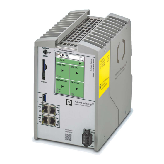
Description of the RFC 4072S Indicators, interfaces, and operating elements 108580A010 Figure 2-9 Structure of the RFC 4072S Remote Field Controller including fan module Key: Touch screen display Mode selector switch Slot for the parameterization memory/card holder (SD card) Ejector for the parameterization memory USB interface (type A USB 3.0 socket) -
Page 40: Security Seal And Test Mark
(ESD) according to EN 61340-5-1. Scope of supply Please note that the SD card (parameterization memory) and the fan module are not sup- plied as standard with the RFC 4072S. For the ordering data, please refer to Section “Accessories” on page 230. -
Page 41: Fan Module
Section “Accessories” on page 230. NOTE: The RFC 4072S can overheat – use the fan module. The RFC can be operated from 0 m to 2000 m above sea level at ambient temperatures up to 40 °C without a fan module. Warning messages and switching off may occur at higher ambient temperatures. -
Page 42: Status And Diagnostics Indicators (Ethernet)
LNK and ACT LEDs Touch screen display The RFC 4072S has a Touch screen display (referred to as “display” in the following). This display shows tiles containing various information on the device and the connected network. The display allows you to retrieve information about the iSPNS 3000 and OPC UA connec- tions, for example. - Page 43 Description of the RFC 4072S DANGER: Chemical burns If the display is damaged, avoid direct skin contact, swallowing or inhaling of escaping flu- ids or gases. Figure 2-13 Display of the RFC You can activate following menu-specific functions by tapping the symbols on the display.
-
Page 44: Structure Of The Display (Diagnostic Display)
RFC 4072S Structure of the display (diagnostic display) The display contains important diagnostic and status information for the RFC and its inter- faces. Depending on the selected view, more detailed information can be selected for indi- vidual items. For example, the IP addresses of the RFC can be requested via the display and set if necessary. -
Page 45: Indicators On The Display
Description of the RFC 4072S 2.9.1 Indicators on the display The following figure shows the general meaning of the indicators in the home menu of the display. Status information for: A: PLCnext (standard controller) B: Safety PLC (iSPNS 3000) C: OPC UA (OPC UA server) -
Page 46: Status Information: Safety Plc (Ispns 3000)
RFC 4072S Safety PLC (iSPNS 3000) Table 2-3 Status information: safety PLC (iSPNS 3000) Indicator Color Meaning Gray The function of the iSPNS 3000 is deactivated. No safety- related program is loaded. Blue Initial state in which the iSPNS 3000 passes through various phases until it is ready for operation (e.g., self-test, synchroni-... -
Page 47: Status Information: Opc Ua (Opc Ua Server)
Green At least one PROFINET device was configured in the PLCnext Engineer software. The RFC 4072S (PROFINET controller) attempts to establish an application relationship to this PROFINET device. Green The RFC 4072S (PROFINET controller) has established an application relationship with at least one configured PROFINET device and exchanges process data with this device. -
Page 48: Status Information: Pn Device (Profinet Device)
(link is present). No application relationship established. BF flashing red. Green An application relationship is established between the higher- level PROFINET controller and the RFC 4072S (PROFINETdevice). Internal firmware error of the RFC 4072S (PROFINET device). 48 / 272 PHOENIX CONTACT 108580_en_02... -
Page 49: Diagnostics Indicators
Description of the RFC 4072S 2.9.3 Diagnostics indicators The diagnostic indicators of all the tiles are displayed in the home menu using virtual LEDs. They have the following meaning: Figure 2-16 Diagnostic indicators in the home menu (LEDs) Safety PLC (safety-related... -
Page 50: Diagnostic Indicators: Pn Control (Profinet Controller)
RFC 4072S PN Control (PROFINET controller) Table 2-8 Diagnostic indicators: PN Control (PROFINET controller) Color Meaning No link status on the Ethernet port and/or no 100-Mbit transmission and/or no full duplex mode present. Flashing Link status present, at least one configured PROFINET device has no PROFINET communication connection. -
Page 51: Home Menu
Description of the RFC 4072S 2.9.4 Home menu Figure 2-17 Home menu The home menu displays the following operating states and diagnostic LEDs: – PLCnext (standard controller) – Safety PLC (iSPNS 3000); LED: FS – OPC UA (OPC UA server) –... -
Page 52: Config Details" Menu
RFC 4072S 2.9.5 “CONFIG DETAILS” menu • Open the “CONFIG DETAILS” menu by tapping the symbol in the home menu. Figure 2-18 “CONFIG DETAILS” menu The “CONFIG DETAILS” menu provides further menus for selection that you can open by tapping the relevant button. -
Page 53: Plcnext Details" Menu (Standard Controller)
• Open the “PLCnext DETAILS” menu by tapping the “PLCnext” tile in the home menu. Figure 2-20 “PLCnext DETAILS” menu (standard controller) The menu shows the following information on the standard controller of the RFC 4072S: – Device temperature –... -
Page 54: Plcnext Details" Menu (Safety-Related Profinet Controller)
RFC 4072S 2.9.7 “PLCnext DETAILS” menu (safety-related PROFINET controller) • Open the “S-PLC DETAILS” menu by tapping the “Safety PLC” tile in the home menu. Figure 2-21 “S-PLC DETAILS” menu (iSPNS 3000) The “S-PLC DETAILS” menu provides further menus for selection that you can open by tap- ping the relevant button. -
Page 55: Opc Ua Details" Menu (Opc Ua Server)
Description of the RFC 4072S Menus in Figure 2-22 on page S-PLC DIAGNOSTICS The menu shows information on iSPNS 3000 diagnostics: – Project name – CRC checksum of the PLCnext Engineer project In PLCnext Engineer, this value can be found in the “Safety Cockpit” editor (“Safety PLC”... -
Page 56: Pn-C Details" Menu (Profinet Controller)
RFC 4072S 2.9.9 “PN-C DETAILS” menu (PROFINET controller) • Open the “PN-C DETAILS” menu by tapping the “PN Control” tile in the home menu. Figure 2-24 “PN-C DETAILS” menu (PROFINET controller) The menu shows information on the PROFINET controller: –... -
Page 57: Usb Interface (Currently Not Supported)
2.10 USB interface (currently not supported) The RFC 4072S is equipped with a USB 3.0 interface. It is designed as a type A USB socket. You can connect a USB memory stick to this interface. We recommend using the following USB stick: USB FLASH DRIVE (Order No. 2402809), USB memory stick, 8 GB. -
Page 58: Interfaces
2.11 Interfaces LAN1 LAN2 LAN3.1 LAN3.2 107586A004 Figure 2-27 Interfaces of the RFC 4072S The RFC 4072S is equipped with the following interfaces: Interfaces Description LAN1 1 x Ethernet 10/100/1000 BASE-T(X); PROFINET: controller interface function LAN2 1 x Ethernet 10/100/1000 BASE-T(X) LAN3.1/LAN3.2... -
Page 59: Ethernet Connection
LAN1 is preconfigured as the PROFINET controller interface. The LAN3.1 and LAN3.2 inter- faces are preconfigured as the device interface. Operating the RFC 4072S as a PROFINET device (firmware version: 2019.0 LTS) If you are operating the RFC as a PROFINET device via the LAN3.1 or LAN3.2 interface, avoid disconnecting and connecting the Ethernet cable during runtime. -
Page 60: Connection Example Of The Ethernet Interfaces
At present the RFC 4072S supports the following connection in a PROFINET system. In the following example, the RFC 4072S is operated as a lower-level PROFINET device connected to a higher-level PROFINET controller (optional). In this case, the connection is established via the LAN3.2 interface. -
Page 61: Mode Selector Switch
Description of the RFC 4072S 2.12 Mode selector switch The mode selector switch is used to define the operating state of the standard controller. The mode selector switch does not influence the operating state of the safety-related PROFINET controller (SPNS). -
Page 62: Power Supply
WARNING: Loss of electrical safety and the safety function when using unsuitable power supplies The RFC 4072S is designed exclusively for protective extra-low voltage (PELV) operation in accordance with EN 60204-1. Only PELV in accordance with the listed standard may be used for the supply. -
Page 63: Figure 2-30 Overload Range With Fall-Back Characteristic Curve
Description of the RFC 4072S Overload range with fall-back characteristic curve 1.1 x I 2.4 x I 6219B070 Figure 2-30 Overload range with fall-back characteristic curve Overload range without fall-back characteristic curve [ ] V [ ] A 1.5 x I... -
Page 64: Directory Structure Of The File System
Directory structure of the file system The RFC 4072S controller works with a Linux operating system. You can access the con- troller via SFTP or via SSH and view the directories and files on the file system (on the SD card) and modify them as necessary. - Page 65 Description of the RFC 4072S Table 2-11 Storage of firmware components in the root file system Directory in the root file system Description /opt/plcnext/Security/TrustStores Directory for storing the TrustStores configured in WBM Each subdirectory corresponds to the name of a TrustStore.
- Page 66 RFC 4072S Table 2-11 Storage of firmware components in the root file system Directory in the root file system Description /opt/plcnext/lttng_traces Directory for storing trace files The directory is created during runtime of the trace controller when the trigger function for storing the trace files is called for the first time. Each time the trigger function of the memory is called, a new subdirectory (trace directory) for storing the current trace data is created.
-
Page 67: Using Sftp To Access The File System
Activate the firewall. Please note: If you use the RFC 4072S as a PROFINET controller, you must authorize all incoming con- nections via all UDP ports if the firewall is activated. Otherwise, establishing a connection to PROFINET devices is not possible. - Page 68 RFC 4072S 68 / 272 PHOENIX CONTACT 108580_en_02...
-
Page 69: Mounting, Removal, Electrical Installation, And Replacement
Mounting, removal, electrical installation, and replacement Safety notes for mounting and removal Only qualified personnel must pack and unpack the RFC 4072S while observing the fol- lowing ESD regulations. WARNING: Loss of electrical safety and the safety function when using unsuitable... - Page 70 IP54 protection. Shielding The shielding ground of the connected twisted pair cables is electrically connected to the RJ45 socket of the RFC 4072S. When connecting network segments, avoid ground loops, potential transfers, and equipotential bonding currents via the braided shield. NOTE: Please observe the following notes when using a shield connection clamp.
-
Page 71: Mounting The Rfc Fan Module Fan Module
Tighten all four M4 screws equally using a recommended tightening torque of 2.2 Nm (3 Nm, maximum) so that they cannot loosen accidentally (e.g., due to vibration). Figure 3-1 Mounting the RFC FAN MODULE fan module 71 / 272 108580_en_02 PHOENIX CONTACT... -
Page 72: Mounting The Rfc 4072S
RFC 4072S Mounting the RFC 4072S Mount the RFC 4072S on 35 mm standard DIN rails with a height of 15 mm (for ordering data, see Section “Accessories” on page 230). The distance between the DIN rail fastening points must not exceed 160 mm (see Figure 3-3 on page 73). -
Page 73: Removing The Rfc 4072S
The SD card is recognized during initialization of the RFC 4072S. Make sure that the SD card has been inserted before switching on the RFC 4072S to enable the device to use it. NOTE: SD card (parameterization memory) – formatting note The SD card is already formatted and is intended for use with Phoenix Contact devices. -
Page 74: Inserting/Removing The Usb Memory Stick
A RFC 4072S malfunction can occur if the USB memory stick is inserted or removed while the RFC 4072S is supplied with power. Only insert or remove the USB memory stick when the power supply of the RFC 4072S is switched off. -
Page 75: Connecting The Interfaces
Connect the Ethernet cable to the Ethernet interface (RJ45 sockets: LAN1, LAN2 or LAN3.1/3.2) of the RFC 4072S. The cable connects the RFC 4072S to a higher-level or lower-level Ethernet network. • Use Ethernet cables according to CAT5 of IEEE 802.3 for operation with up to 100 Mbps. -
Page 76: Connecting The Supply Voltage
107586A006 Figure 3-6 Connecting the supply voltage Please note that the RFC 4072S requires approximately two minutes to start up. This is due to the comprehensive selftests the device must perform. The status is indicated on the display. 76 / 272... -
Page 77: Replacing The Rfc 4072S
Phoenix Contact. Information on compatible devices can be found on the Internet at phoenixcontact.com. WARNING: Unintentional machine startup Do not replace the RFC 4072S while the power is connected. Do not remove the device until: –... -
Page 78: Figure 3-8 Disconnecting The Ethernet Connection
RFC 4072S If present, disconnect the Ethernet connection. 107586A007 Figure 3-8 Disconnecting the Ethernet connection Remove the RFC to be replaced from the DIN rail. 108580A009 Figure 3-9 Removing the RFC from the DIN rail 78 / 272 PHOENIX CONTACT... -
Page 79: Figure 3-10 Removing The Fan Module
Unscrew the four screws used to fix the fan module to the bottom of the RFC. Make sure that the fan module does not fall down after unscrewing the screws. 108580A004 Figure 3-10 Removing the fan module Take the replacement device out of its packaging. 79 / 272 108580_en_02 PHOENIX CONTACT... -
Page 80: Figure 3-11 Mounting The Rfc Fan Module Fan Module
Figure 3-11 Mounting the RFC FAN MODULE fan module Mount the replacement device according to Section “Mounting the RFC 4072S” on page 72. Make sure that the device is secured on the DIN rail. Snap the RFC onto the DIN rail and check that it is securely locked in place (see Figure 3-12). -
Page 81: Figure 3-13 Establishing The Ethernet Connection
RFC 4072S. 13. When restarting the RFC 4072S after replacement, first carry out the appropriate mea- sures specified in the validation plan for the machine/system. Follow the instructions and corresponding notes in Section “Restart after replacing the RFC 4072S”... - Page 82 RFC 4072S 82 / 272 PHOENIX CONTACT 108580_en_02...
-
Page 83: Startup And Validation
For initial startup, proceed as described in Table 4-1. The following table describes all the steps from unpacking the RFC 4072S through mount- ing/installation to startup. Table 4-1 Steps for initial startup of the RFC 4072S... - Page 84 The planned system/machine safety function is only available following validation. Please note that the RFC 4072S requires approximately two minutes to start up. This is due to the comprehen- sive selftests the device must perform. The status is indicated on the display.
-
Page 85: Figure 4-6: Defining A Project Password
Startup and validation Table 4-1 Steps for initial startup of the RFC 4072S Step Relevant section and literature Check the settings for management/diagnostic variables – Section “Safety-related mode of operation of the and adapt the settings, if necessary. RFC 4072S” on page 25 –... -
Page 86: Restart After Replacing The Rfc 4072S
Section “Safety notes for mounting and removal” on page 69 ESD regulations. Mount the device in accordance with your application. Section “Mounting the RFC 4072S” on page 72 Insert the parameterization memory. Section “Inserting/removing the SD card (parameterization memory)” on page 73 Connect the device to an Ethernet network. -
Page 87: Steps For Restarting The Rfc 4072S
RFC 4072S. Please note that the RFC 4072S requires approximately two minutes to start up. This is due to the comprehen- sive selftests the device must perform. The status is indicated on the display. -
Page 88: Example Startup Of The Rfc 4072S
Please note that in principle you can use Axioline F and/or Inline bus couplers as well as the corresponding I/O devices and devices from other manufacturers as lower-level PROFINET devices and/or PROFIsafe F-Devices. In the following example, two Axioline F bus couplers are coupled to the RFC 4072S PROFINET controller on a lower level. Example configuration... -
Page 89: Integration Of The Rfc 4072S In Plcnext Engineer As A Profinet Controller
Startup and validation 4.3.2 Integration of the RFC 4072S in PLCnext Engineer as a PROFINET controller The following sections describe how to: – Create a new project in PLCnext Engineer. – Assign IP addresses to the RFC. – Read the PROFINET devices connected to the RFC. -
Page 90: Software Requirements
You must activate PLCnext Engineer via the Phoenix Contact Activation Wizard. • Download the Phoenix Contact Activation Wizard at the link provided above. • Follow the instructions in the Phoenix Contact Activation Wizard to activate your PLCnext Engineer license. 90 / 272 PHOENIX CONTACT... -
Page 91: User Interface
The “COMPONENTS” area contains all of the components available for the project. The components are subdivided according to their function. Cross-functional area The cross-functional area contains functions that extend across the entire project (e.g., ERROR LIST, WATCHES, LOGGING, and RECYCLE BIN). 91 / 272 108580_en_02 PHOENIX CONTACT... -
Page 92: Creating A New Project
Creating a new project • Open PLCnext Engineer. • Click on the “Empty RFC 4072S project” project template on the start page. The project template for an empty RFC 4072S project opens. Figure 4-3 Start page, “Empty RFC 4072S project” project template •... -
Page 93: Configuring The Controller Ip Settings
In the Windows Control Panel, check the settings for your PC network adapter. • If necessary, adjust these settings so that the RFC 4072S can be accessed in your net- work via the IP address used in the example project. -
Page 94: Setting The Ip Address Range
RFC 4072S NOTE: Limited number of gateway addresses In order to avoid uncontrolled transmission of data via all Ethernet interfaces, do not enter more than one gateway address in the “Ethernet” view in the “Settings” editor of the con- troller editor group in PLCnext Engineer. -
Page 95: Setting The Ip Address
PLCnext Engineer automatically assigns an IP address to the controller from the set IP address range (see Section 4.5.3, “Setting the IP address range”) as soon as a connection is established to the controller (see Section 4.7). 95 / 272 108580_en_02 PHOENIX CONTACT... -
Page 96: Defining A Project Password
RFC 4072S Setting the IP address • Select “manual” in the “IP address assignment mode” drop-down list. manually • Enter the IP address, subnet mask, and gateway in the respective input fields. PLCnext Engineer assigns the manually set IP address to the controller as soon as a con-... -
Page 97: Connecting To The Controller
IP settings of the online device found in the network. If you select the device (“Select online device here”) under “Name of Station (Online)”, the controller found in the network (the online device) receives the IP settings of the configured controller. 97 / 272 108580_en_02 PHOENIX CONTACT... -
Page 98: Figure 4-9 Successful Assignment Of The Configured Controller To An Online Device
RFC 4072S • Select the desired device. The configured controller has now been assigned to an online device. If the IP address of an online device found in the network already matches the IP address of the configured controller, the online device is automatically assigned to the configured controller. -
Page 99: Figure 4-10 User Authentication: Entering A User Name And Password
Enter the user name and password. icon next to the controller node and bold font in the “PLANT” area indicates that connection was successful (see Figure 4-11). Figure 4-11 Successful connection to the controller button also indicates successful connection. 99 / 272 108580_en_02 PHOENIX CONTACT... -
Page 100: Configuring Profinet Devices
RFC 4072S Configuring PROFINET devices 4.8.1 Adding PROFINET devices • Double-click on the “Profinet (x)” node in the “PLANT” area. The “/ Profinet” controller editor group opens. • Select the “Device List” editor. Add the PROFINET devices in the “Device List” editor. To do this, proceed as follows: •... -
Page 101: Assigning Online Devices (Device Naming)
You can see the configured PROFINET devices under “Name of Station (Project)”. You can see the PROFINET devices that have been found online in the network (online devices) under “Name of Station (Online)”. Figure 4-15 Assigning online devices 101 / 272 108580_en_02 PHOENIX CONTACT... -
Page 102: Adding I/O Modules
RFC 4072S If you select the PROFINET device (“Select online device here”) under “Name of Station (Online)”, the PROFINET device found in the network (the online device) receives the IP set- tings of the configured PROFINET device (device naming). Please note: The PROFINET device does not have an IP address in the delivery state. -
Page 103: Figure 4-17 Role Picker For Selecting I/O Modules
Entering the project password • Click on the arrow in the dialog to confirm your entry. Successful login to the safety-related area is indicated by the text highlighted in yellow shown in Figure 4-19 on page 104: 103 / 272 108580_en_02 PHOENIX CONTACT... -
Page 104: Figure 4-19: Successful Login To The Safety-Related Area
RFC 4072S Figure 4-19 Successful login to the safety-related area The I/O module is added and shown in the “PLANT” area under the “Profinet (x)” node for the respective PROFINET device (see Figure 4-20). • Proceed as described above to add more I/O modules. -
Page 105: Figure 4-21 Reading I/O Modules Of A Profinet Device Automatically
Repeat this step for all PROFINET devices in the project. The figure below shows all the manually and automatically added I/O modules in the exam- ple project. Figure 4-22 Axioline F modules in the example project 105 / 272 108580_en_02 PHOENIX CONTACT... -
Page 106: Programming In Accordance With Iec 61131-3 - Non-Safety-Related Example Program
RFC 4072S Programming in accordance with IEC 61131-3 – Non-safety-related example program Please note: ® ® Programming with C++ or MATLAB Simulink is not described in this user manual. ® ® Detailed information on programming with C++ or Matlab Simulink is available in the PLCnext Community at plcnext-community.net. -
Page 107: Figure 4-24: "Add Program" Context Menu
If you have created a new POU, you will be prompted to select the programming language when you open the worksheet for the first time (see Figure 4-23). Once you have selected the programming language, the POU editor group opens. 107 / 272 108580_en_02 PHOENIX CONTACT... -
Page 108: Creating Variables
RFC 4072S 4.9.2 Creating variables The following table shows the variables to be created in the non-safety-related example pro- gram (logical ANDing), which will later be connected to process data in PLCnext Engineer. Table 4-4 Input/output variables in the example (logical ANDing) -
Page 109: Creating A Program
Click on the arrow on the right next to the designation of the program editor. • From the drop-down list that opens, select the desired code worksheet. Figure 4-27 Adding a code worksheet to a POU 109 / 272 108580_en_02 PHOENIX CONTACT... -
Page 110: Instantiating A Program
Individual tasks are coordinated and processed in the Execution & Synchronization Man- ager (ESM). The RFC 4072S uses a dual core processor and has one ESM (“ESM1” and “ESM2” in the “Tasks and Events” editor) per processor core. -
Page 111: Assigning Process Data
You can also see an overview of all the available variables when you click on the node for the controller in the “PLANT” area and also open the “Data List” editor there. You can also assign the process data at this point. 111 / 272 108580_en_02 PHOENIX CONTACT... -
Page 112: Figure 4-30 Role Picker For Selecting Process Data
RFC 4072S • To assign a process data item to a variable, click on “Select Process Data Item here” in the “Process Data Item” column. The role picker opens. Only the process data that you can actually assign to the respective variable is displayed in the role picker. -
Page 113: Figure 4-32: Example: List Of All Available Process Data Items
Figure 4-33 Role picker for selecting variables • In the role picker, select the variable that you want to assign to the respective process data item. The variable is assigned to the process data item. 113 / 272 108580_en_02 PHOENIX CONTACT... -
Page 114: For Programs In Accordance With Iec 61131-3 With In And Out Ports
RFC 4072S Figure 4-34 Selected variable • Proceed as described above to add more process data items. 4.11.2 For programs in accordance with IEC 61131-3 with IN and OUT ports If you have created variables as IN and/or OUT ports in your program, the process data is assigned in the “Port List”... -
Page 115: Figure 4-36: Role Picker For Selecting In Ports
Select the OUT port that you want to assign to the relevant IN port in the role picker. The OUT port is assigned to the IN port. • Proceed as described to add other OUT ports. 115 / 272 108580_en_02 PHOENIX CONTACT... -
Page 116: Transferring A Project To The Controller
If necessary, enter the user name and password in the dialog that opens. The project is compiled, transferred to the controller, and executed. If startup was carried out successfully, the following appears on the RFC 4072S display: Figure 4-38 Controller in the RUN state, PROFINET controller in the ACTIVE state If an installation error prevents the system from starting up, a corresponding error message appears on the display and in PLCnext Engineer. -
Page 117: Displaying Online Values
The online values of the variables used in the “Main” POU are displayed in the “Variables” and “Code” editors. Figure 4-39 “Variables” editor: online values of the variables used Figure 4-40 “Code” editor: online values of the variables used 117 / 272 108580_en_02 PHOENIX CONTACT... -
Page 118: Creating A Plcnext Engineer Hmi Application
RFC 4072S 4.14 Creating a PLCnext Engineer HMI application In PLCnext Engineer, you can create a PLCnext Engineer HMI application, which can be used to visualize, monitor, and control the application on your controller. For information on creating a PLCnext Engineer HMI application, refer to the “Installing and operating the PLCnext Engineer software”... -
Page 119: Programming In Accordance With Iec 61131-3 - Safety-Related Example Program
In the “PROFIsafe addressing” view, check the setting for the F_Source_Add F- Address. In the example, set F_Source_Add to “1024”. If necessary, adapt the value of F_Source_Add to your application. An adjustable range of “1 … 65535 ”, maximum, is permitted. 119 / 272 108580_en_02 PHOENIX CONTACT... -
Page 120: Figure 4-42: F-Address Of The Profisafe F-Device: F_Dest_Add (F_Destination_Address)
RFC 4072S F_Destination_Address (F_Dest_Add) When using the RFC 4072S as an F-Host, an adjustable range of “1 … 65534 ”, maxi- mum, is permitted for the F-Addresses of the safety modules used (F_Dest_Add / F_Des- tination_Address). Please note the following points: –... -
Page 121: Management/Diagnostic Variables For F-Devices
In the “Profisafe - device diagnostic variables” view, you can specify which manage- ment/diagnostic variables are to be generated for each F-Device configured in the project (see Figure 4-43). Figure 4-43 Management/diagnostic variables for each configured F-Device 121 / 272 108580_en_02 PHOENIX CONTACT... -
Page 122: Figure 4-44 Management/Diagnostic Variables For All Configured F-Devices
RFC 4072S In the “Profisafe - summarizing diagnostic variables” view, you can specify which manage- ment/diagnostic variables are to be globally generated once for all PROFIsafe F-Devices configured in the project (see Figure 4-43). Figure 4-44 Management/diagnostic variables for all configured F-Devices Created variables are displayed in the “Data List”... -
Page 123: Checking/Setting Safety Parameters For Configured F-Devices
If you are not currently logged into the safety-related area, you will now be prompted to enter the password in the “PROJECT AUTHENTICATION” dialog that opens (see “Project login required” on page 103). Figure 4-46 “Safety Parameters” editor: AXL F PSDI8/4 1F 123 / 272 108580_en_02 PHOENIX CONTACT... -
Page 124: Figure 4-47 "Safety Parameters" Editor: Axl F Psdo8/3 1F
RFC 4072S • Set the required safety parameters. In the example in Figure 4-46, these are F-Address F_Dest_Add, watchdog time F_WD_Time, and the assignment of channels 1 and 2 of the inputs. If necessary, adapt the settings to your application. -
Page 125: Creating Variables (Exchange Variables)
Click on the button to generate a new variable group. • Rename the new variable group “Exchange”. • Enter the names of the variables in the “Variable (PLC)” column in turn as shown in Figure 4-48. 125 / 272 108580_en_02 PHOENIX CONTACT... -
Page 126: Figure 4-49: "Add Variable (Safety Plc)" Context Menu
RFC 4072S • In the “Variable (Safety PLC)” column, select “Add Variable (Safety PLC)” in the context menu for each variable you created earlier in turn (see Figure 4-49). Figure 4-49 “Add Variable (Safety PLC)” context menu After you have created the exchange variables, you need to specify the data direction (I/Q). -
Page 127: Opening A Safety-Related Pou
• Then click on the arrow next to “Local (x)”, then on “Programs (x)”. • Double-click on the desired safety-related POU (in the example: “S_Main” program). The editor group for the selected POU opens. 127 / 272 108580_en_02 PHOENIX CONTACT... -
Page 128: Creating Variables
RFC 4072S 4.15.6 Creating variables Creating variables for safe The following table shows the variables to be created in the safety-related example program logical ANDing (safe logical ANDing), which will later further be used in PLCnext Engineer. Table 4-5 Input/output variables in the example (safe logical ANDing) -
Page 129: Creating A Safety-Related Program
In addition, all the variables from the “Exchange” variable group that were created earlier (see Figure 4-48 on page 125) are connected to the corresponding exchange variables that were created earlier. Creating a program To create a program, proceed as follows: • Select the program editor. 129 / 272 108580_en_02 PHOENIX CONTACT... - Page 130 RFC 4072S The program editor is referred to as “Code” by default. You can change the designation of the program editor as desired. • Create the program as shown in Figure 4-53 on page 130. Figure 4-53 Safety-related example program...
-
Page 131: Assigning Process Data
In the “Process Data Item” column, use the role picker to assign the corresponding pro- cess data (see also Section “Assigning process data” on page 111) to all variables (see marked section in Figure 4-54). Figure 4-54 Assigned safety-related process data 131 / 272 108580_en_02 PHOENIX CONTACT... -
Page 132: Transferring A Project To The Controller
The project is compiled and transferred to the standard controller. Execution of the project is started and the standard controller (“PLCnext” tile) switches to the “RUN” state. If startup was carried out successfully, the following appears on the RFC 4072S display: Figure 4-55... -
Page 133: Figure 4-56 Standard Controller In The "Run" State
If an installation error prevents the system from starting up, a corresponding error message appears on the display and in PLCnext Engineer. The iSPNS 3000 is in the FAIL state because the example project has not yet been trans- ferred to the iSPNS 3000. 133 / 272 108580_en_02 PHOENIX CONTACT... -
Page 134: Transferring A Safety-Related Project To The Safety-Related Controller (Defining A Controller Password, If Necessary)
RFC 4072S 4.16.2 Transferring a safety-related project to the safety-related controller (defining a controller password, if necessary) To transfer the project to the safety-related controller, proceed as follows: • Double-click on the “Safety PLC (x)” node in the “PLANT” area. -
Page 135: Figure 4-58: Information Dialog: Prevent Any Hazard Posed By The Safety-Related Controller Being Started And Stopped
The project is compiled and transferred to the safety-related controller. Execution of the safety-related project is started and the safety-related controller (“Safety PLC” tile) switches to the “RUN” state. If startup was carried out successfully, the following appears on the RFC 4072S display: Figure 4-59 Safety-related controller in the RUN state... -
Page 136: Figure 4-60 Safety Cockpit: Safety-Related Controller In The "Run" State - Safe Run
RFC 4072S The following information is displayed in the “Safety Cockpit” editor: Figure 4-60 Safety Cockpit: safety-related controller in the “RUN” state – Safe Run If an installation error prevents the system from starting up, a corresponding error message appears on the display and in PLCnext Engineer. -
Page 137: Figure 4-61 "Variables" Editor (S_Main): Online Values Of The Variables Used
Open the instance editor of the “S_Main” POU by double-clicking on the “S_Main : S_Main” node. The online values of the variables used in the “S_Main” POU are displayed in the “Variables” and “Code” editors. Figure 4-61 “Variables” editor (S_Main): online values of the variables used 137 / 272 108580_en_02 PHOENIX CONTACT... -
Page 138: Figure 4-62 "Code" Editor (S_Main): Online Values Of The Variables Used
RFC 4072S Figure 4-62 “Code” editor (S_Main): online values of the variables used 138 / 272 PHOENIX CONTACT 108580_en_02... -
Page 139: Figure 4-63 Exiting Safe Mode - Switching To Debug Mode
Exiting safe mode – switching to debug mode Debug mode is indicated as follows on the display: Figure 4-64 Display: debug mode indicated • To disable debug mode and switch to safe mode, click on the button. 139 / 272 108580_en_02 PHOENIX CONTACT... -
Page 140: Figure 4-65 Exiting Debug Mode - Switching To Safe Mode
RFC 4072S WARNING: Make sure that your system/machine cannot pose a hazard to people or equipment. Figure 4-65 Exiting debug mode – switching to safe mode 4.19 Operator acknowledge F-Devices whose communication relationship with the iSPNS 3000 is aborted, e.g., due to a communication error, are passivated. -
Page 141: Figure 4-66 Plcnext Engineer - Passivated Profisafe F-Devices
PLCnext Engineer – Passivated PROFIsafe F-Devices In the example in Figure 4-66, the safe inputs and safe outputs have entered the SAFE- FALSE state. This behavior is due to the passivation of the F-Devices. 141 / 272 108580_en_02 PHOENIX CONTACT... - Page 142 RFC 4072S 142 / 272 PHOENIX CONTACT 108580_en_02...
- Page 143 In this state, the outputs of the F-Devices are set to zero after the parameterized F_WD_TIME for the relevant output has elapsed at the latest. The PROFIsafe system switches to the safe state. 143 / 272 108580_en_02 PHOENIX CONTACT...
- Page 144 Please note that for all error codes listed in Table 5-1 on page 146, the FS LED is always on in the diagnostic display of the RFC 4072S and the FS bit is set in the SPNS_DI- AG_STATUS_REG register. The iSPNS 3000 enters the failure state.
- Page 145 If errors occur, always provide the service/support personnel from Phoenix Contact with the complete error code. These details provide important information for error analysis and repair. The error codes are displayed on the RFC 4072S display, in the SPNS_DI- AG_PARAM_REG and SPNS_DIAG_PARAM_2_REG diagnostic parameter registers, or in the PLCnext Engineer software.
- Page 146 Table 5-1 RFC 4072S error codes Error code (hex) Error cause Remedy or response 0x8001 (0x9001) Please contact your nearest Phoenix Contact represen- Internal error tative. 0x8007 (0x9007) • Check whether the non-safety-related project is loaded on the standard controller.
- Page 147 0x80D5 (0x90D5) 0x80E1 (0x90E1) 0x80E8 (0x90E8) • Switch off the supply voltage of the RFC 4072S. • Insert a properly working SD card containing the project in the device or carry out the project down- loads described in the note on “Order of project downloads”...
- Page 148 RFC 4072S error codes Error code (hex) Error cause Remedy or response 0x80EA (0x90EA), 0x80EB (0x90EB) 0x8101 (0x9101) 0x8107 (0x9107) Please contact your nearest Phoenix Contact represen- Internal error tative. 0x8110 (0x9110), 0x8111 (0x9111) 0x8121 (0x9121) 0x8125 (0x9125) Unknown version of the “pniodev.bin”...
- Page 149 For proper startup of the device, the supply voltage must only be switched on 30 seconds after the display goes out at the earliest. If the procedure described above does not rectify the error, please contact your nearest Phoenix Contact rep- resentative. 149 / 272 108580_en_02...
- Page 150 Follow the instructions provided in the note on “Order of project downloads” above this table. • If the error cannot be removed, please contact your nearest Phoenix Contact representative. Please contact your nearest Phoenix Contact represen- 0x812B (0x912B) Internal error tative. Maximum number of supported F-...
- Page 151 0x824C (0x924C) Check the ambient conditions (e.g., sufficient ventilation Ambient temperature is not in the speci- 0x824D (0x924D) in the control cabinet) and operate the RFC 4072S fied range. within the range specified. 0x824E (0x924E) 0x825C (0x925C) Internal error...
-
Page 152: Figure 5-1 Asyncom_Pn_1 Function Block
Depending on the error type, errors that are diagnosed in the Inline PROFIsafe modules from Phoenix Contact used are transmitted to the RFC 4072S as diagnostic messages using PROFINET. The product documentation for the modules used contains an overview of the diagnosed errors, their causes, effects, and possible measures for error removal, as well as informa- tion regarding module behavior following acknowledgment of diagnostic messages. -
Page 153: Figure 5-2 Function Block Pnfd_Axl_Diag_1
In the safety logic, take measures to prevent this edge change resulting in unexpected machine/system startup or restart. Note for starting applications Also observe these notes to prevent unexpected machine startup following acknowledg- ment by means of operator acknowledgment. 153 / 272 108580_en_02 PHOENIX CONTACT... - Page 154 RFC 4072S 154 / 272 PHOENIX CONTACT 108580_en_02...
- Page 155 Maintenance The RFC 4072S does not require maintenance. The RFC 4072S does not require repeat testing during mission time. Caring for the display – To clean the display, wipe gently using a soft absorbent cotton cloth soaked in ethanol.
-
Page 156: Figure 6-1 Replacing The Rfc Fan Module Fan Module
RFC 4072S Replacing the RFC FAN MODULE fan module NOTE: Potential RFC 4072S malfunction The fan module must not be replaced during operation. The RFC must be switched off before the fan module can be replaced. To replace the fan module, remove the RFC from the DIN rail. - Page 157 NOTE: Potential RFC malfunction Do not interrupt the RFC 4072S supply voltage during the firmware update process. Inter- ruption of the supply voltage can result in a malfunction on the RFC 4072S. In this case, the device can no longer be used.
-
Page 158: Figure 6-2 Standard Controller In The "Stop" State
RFC 4072S Figure 6-2 Standard controller in the “STOP” state • Double-click on the “Safety PLC” node in the “PLANT” area. The editor group of the safe PLC opens. • Select the “Safety Cockpit” editor. • Click on the button to connect PLCnext Engineer to the safe PLC. - Page 159 SPNS state: Debug Stop You can update the non-safety-related device firmware via the Web-based management system of the RFC 4072S or the Linux shell using a command-line tool. For information about updating the firmware using a command-line tool, please refer to Section 6.5.1...
- Page 160 • Follow the instructions of the installation wizard. During installation, the update file (*.raucb) and files containing device-specific information (such as change notes and Phoenix Contact software license terms) are copied to the selected destination directory. • Open the SFTP client software (e.g., WinSCP).
- Page 161 Maintenance, replacement, firmware update, repair, decommissioning, and disposal The “SYSTEM INFORMATION” submenu displays the updated firmware version (see A in Figure 6-6). The update file is automatically deleted from the /opt/plcnext directory. 161 / 272 108580_en_02 PHOENIX CONTACT...
- Page 162 RFC 4072S Repair Repairs may not be carried out on the RFC 4072S. Send faulty devices with detailed error information (see Section “Errors, diagnostic messages and troubleshooting” on page 143) to Phoenix Contact. NOTE: Possible RFC malfunction – Do not open housing It is strictly prohibited to open the RFC 4072S.
- Page 163 Additional settings as well as features and what you need to know about the RFC 4072S Additional settings as well as features and what you need to know about the RFC 4072S Resetting the controller to the default settings •...
- Page 164 The procedure for assigning the IP address settings is essentially the same for the LAN1, LAN2 and LAN3.1/3.2 interfaces. Interface LAN2 is described in this example. You can view and change the IP address defined in the RFC 4072S via the display at any time, even during operation.
- Page 165 Additional settings as well as features and what you need to know about the RFC 4072S The following menu shows the default IP-settings of the LAN2 interface: Figure 7-3 “CONFIG DETAILS, … EDIT LAN2” menu: default settings • Select the “IP address: …” menu item.
- Page 166 RFC 4072S The following menu appears: Figure 7-5 “CONFIG DETAILS, … EDIT LAN2” menu: LAN2 IP address • Confirm your entries by tapping The activated symbol appears as a pressed button when it is tapped. This change in appear- ance is a visual indicator that tapping has been recognized by the system (A in Figure 7-6).
- Page 167 Additional settings as well as features and what you need to know about the RFC 4072S Parameterization memory: directory structure and access The parameterization memory is accessed via the SFTP protocol. SFTP client software is required for this (e.g., WinSCP).
- Page 168 The editor group of the “/ PLCnext” controller opens. • Select the “Online Parameters” editor. Figure 7-10 Realtime clock settings for the RFC 4072S • Click on the button to read the values from the device and apply them to the proj- ect.
- Page 169 Additional settings as well as features and what you need to know about the RFC 4072S • Click on the button to write the configured values to the device. Download changes Startup parameterization of PROFINET devices In a PROFINET network used in systems manufacturing, devices must be coupled and decoupled.
- Page 170 RFC 4072S Safety notes for starting applications Take the following into consideration when determining and programming the start condi- tions for your machine or system: – The machine or system may only be started if it can be ensured that nobody is present in the danger zone.
- Page 171 The substitute value behavior for the input data of the controller must be specified in your PLCnext Engineer project. By default, the input data of the RFC 4072S is set to zero if the connection to a PROFINET device is interrupted.
-
Page 172: Overview Of The Function Blocks
RFC 4072S Function blocks for handling files on the parame- terization memory The function blocks are used to access files from within the application program. Some of the blocks support multiple instantiation. This means that it is possible to work with a number of different files within the same project. - Page 173 Additional settings as well as features and what you need to know about the RFC 4072S Function blocks for Ethernet communication The function blocks are used to establish Ethernet communication between two communi- cation partners. The IP communication blocks listed below enable IEC 61131-5-compliant communication between controllers via Ethernet or communication between controllers and Ethernet devices via TCP/IP or UDP/IP.
- Page 174 7.11 Web server The RFC 4072S has a web server. With its visualization software, you can use the web server to visualize control variables, for example, in a web browser. The Web-based man- agement system of the RFC 4072S is also available via the web server (see Section “Web-...
- Page 175 System variables grouped into structures Certain system variables of the RFC 4072S are grouped into structures in PLCnext Engineer. You can display these system variables and elements of the structure in the PLCnext Engineer Init Value Configuration editor.
-
Page 176: Spns System Variable And Elements Of The Spnsv2_Type Structure
Diagnostic states are important for system operation. If error messages occur, the process has to be stopped in case of doubt. For this purpose, controllers from Phoenix Contact pro- vide the following status information for the PROFINET network. - Page 177 WORD Build number of the iSPNS 3000 hardware FPGA NUM_OF_ACTIVE_ARS UINT Number of active PROFINET application relations (AR) FW_UPDATE_STATUS UINT Status of safety-related firmware update SOFT_RESET_REG WORD Software reset register of the iSPNS 3000 177 / 272 108580_en_02 PHOENIX CONTACT...
- Page 178 RFC 4072S The following table describes the information of the individual bits (0 … 15) in the diagnostic status register (SPNS.DIAG.STATUS_REG.xxx) Table 8-2 Elements in the diagnostic status register (SPNS.DIAG.STATUS_REG.xxx) System variable/elements Type Meaning SPNS See above See above DIAG...
- Page 179 Loading and starting of the safety-related application program Synchronization of the iSPNS 3000 and the standard controller Initialization of the iSPNS 3000 F-Host for I/O channel communication The variables indicate the RUN and DEBUG operating states of the iSPNS 3000. 179 / 272 108580_en_02 PHOENIX CONTACT...
-
Page 180: Spns.diag.status_Reg
RFC 4072S SPNS.DIAG.STATUS_REG – Meaning of the individual bits The SPNS.DIAG.STATUS diagnostic status register contains the status information of the iSPNS 3000. It mirrors the state of the iSPNS 3000 at all times including any error states that have occurred on the iSPNS 3000. Additional information and error parameters, in particular in the failure state (FS), are included in the relevant diagnostic parameter registers of the iSPNS 3000 (SPNS.DIAG.PARAM_REG and SPNS.DIAG.PARAM_2_REG), and in the... -
Page 181: Contents Of Bits 5 And 6 And Corresponding Led Indicators
This bit is set as soon as an error has been detected, which sets the iSPNS 3000 to the fail- ure state. The corresponding additional error code is included in this state in the diagnostic parameter registers of the iSPNS 3000 (SPNS.DIAG.PARAM_REG and SPNS.DIAG.PARAM_2_REG). Res. Reserved 181 / 272 108580_en_02 PHOENIX CONTACT... -
Page 182: Spns_V2_Profisafe_Diag System Variable And Elements Of The Profisafe_Diag_Out Structure
RFC 4072S The SPNS_V2_PROFISAFE_DIAG system variable uses the PROFISAFE_DIAG_OUT structure to provide further information about the iSPNS 3000. Table 8-5 SPNS_V2_PROFISAFE_DIAG system variable and elements of the PROFISAFE_DIAG_OUT structure System variable/elements Type Meaning SPNS_V2_PROFISAFE_DIAG PROFIS- The structure provides PROFIsafe diagnostic information of the AFE_DI- individual configured F-Devices. -
Page 183: Figure 4-43: Management/Diagnostic Variables For Each Configured F-Device
F-Device is reset. F_ADDR_XXXXX_PASS_OUT *) BOOL F-Device XXXXX is passivated. Possible reasons for passivation: – Programmed passivation via the F_ADDR_XXXXX_PASS_ON system variable – Communication, device, and parameterization errors (see F_AD- DR_XXXXX_ACK_REQ system variable) 183 / 272 108580_en_02 PHOENIX CONTACT... -
Page 184: Management/Diagnostic Variables For Each Configured F-Device
RFC 4072S Table 8-6 Management/diagnostic variables for each configured F-Device System variable Type Meaning F_ADDR_XXXXX_ACK_REQ *) BOOL F-Device XXXXX requires an operator acknowledge request after removing an error. Possible reasons for activating the operator acknowledge request: – Communication error (CRC, F_WD_TIME_OUT) –... - Page 185 If the cause has been removed, the F_ADDR_XXXXX_WD_- TIME_OUT variable is set to FALSE again. F_ADDR_XXXXX_IPAR_OK *) BOOL F-Device indicates that the iParameters have been applied This variable is set when the F-Device indicates that it has applied the iParameters. 185 / 272 108580_en_02 PHOENIX CONTACT...
- Page 186 RFC 4072S Table 8-6 Management/diagnostic variables for each configured F-Device System variable Type Meaning F_ADDR_XXXXX_IPAR_EN *) BOOL Initiate application of the iParameters This variable is set in the application in order to initiate the application of the iParameters. Intentionally setting of the F_ADDR_XXXXX_IPAR_EN variable starts the process for applying the iParameters.
-
Page 187: Management/Diagnostic Variables For F-Devices
DR_XXXXX_ACK_REI or ACK_REI_GLOBAL variables. If the cause has been removed, the F_ADDR_XXXXX_DEVICE FAULT variable is set to FALSE again. For information on which errors cause the used F-Device to control this variable, please refer to the device-specific user documentation. 187 / 272 108580_en_02 PHOENIX CONTACT... - Page 188 RFC 4072S Table 8-7 Management/diagnostic variables for F-Devices [...] System variable Type Meaning CE_CRC_GLOBAL BOOL Communication error (F_CE_CRC) This parameter is set if at least one of the following reasons applies: – At least one F-Device has detected a communication error during operation that was caused by an incorrect CRC checksum.
-
Page 189: Profinet System Variables (Profinet Controller Functionality)
No desired configuration has been loaded by PLCnext Engineer. PNIO_CONFIG_STATUS_CFG_FAULT BOOL The desired PROFINET controller configuration has not been applied due to a serious error. Please contact Phoenix Contact. PNIO_FORCE_FAILSAFE BOOL All PROFINET devices are prompted to set their configured sub- stitute values. -
Page 190: Profinet System Variables (Profinet Device Functions)
RFC 4072S If one of these values is set, it is now possible to decide from the program whether the sys- tem should continue operating. For example, system errors such as maintenance require- ment and maintenance demand can only result in a message to the service personnel, which informs them of the location, cause, and urgency of the error. -
Page 191: System Variables For The Tcp_Socket, Udp_Socket, And
System variables for the TCP_SOCKET, UDP_SOCKET, and TLS_SOCKET function blocks System variable Type Meaning IP_ACTIVE_SOCKETS UINT Number of IP sockets opened using the TCP_SOCKET and UDP_SOCKET function blocks TLS_ACTIVE_SOCKETS UINT Number of IP sockets opened using the TLS_SOCKET function block 191 / 272 108580_en_02 PHOENIX CONTACT... -
Page 192: Device_State System Variable And Elements Of The Device_State_4Xxx_Type Structure
RFC 4072S DEVICE_STATE The DEVICE_STATE system variable uses the DEVICE_STATE_4xxx_TYPE structure to provide information about the temperature of the processor board, the optional fan module, and the processor load. Table 8-13 DEVICE_STATE system variable and elements of the DEVICE_STATE_4xxx_TYPE structure... - Page 193 UDINT SUB_TYPE Name of exception SUB_TYPE_ID UDINT TASK_NAME STRING Name of the ESM task in which the exception was trig- gered PROGRAM_NAME Name of the program instance in which the exception was triggered INFORMATION 193 / 272 108580_en_02 PHOENIX CONTACT...
-
Page 194: Hmi_Status System Variable And Elements Of The Hmi_Status_Type Structure
RFC 4072S HMI_STATUS The HMI_STATUS system variable uses the HMI_STATUS_TYPE structure to provide information about the web server that can be programmed in PLCnext Engineer. Table 8-15 HMI_STATUS system variable and elements of the HMI_STATUS_TYPE structure System variable/elements Type Meaning... - Page 195 As the web server operates using the Hyper Text Transfer Protocol, a web browser can be used. Access is via URL “http://IP address of the device”. Example: “http://192.168.1.10”. You can call WBM via every Ethernet interface of the RFC 4072S. Calling Web-based management – Valid IP address required WBM can only be called using a valid IP address.
- Page 196 67 Section “Parameterization memory: directory structure and access” on page 167 Initial access: The RFC 4072S welcome page is shown when accessing the controller web server for the welcome page first time. Figure 9-1...
- Page 197 Alternatively, you can enter URL “http://IP address of the controller/wbm” (example: “http://192.168.1.10/wbm”) in your browser address field. In this case, WBM is displayed immediately. The welcome page remains accessible via URL “http://IP address of the controller/wel- come”. 197 / 272 108580_en_02 PHOENIX CONTACT...
- Page 198 RFC 4072S Licenses and legal information The RFC 4072S uses a Linux operating system. All the license information stored on the RFC can be called using the “Licenses and Legal Information” link on every page of WBM: • Click on the “Licenses and Legal Information” link on the bottom of a WBM page.
- Page 199 You can change the language for the WBM user interface in the top left of the web browser window. Figure 9-3 WBM user interface: selecting the language Click the “Deutsch” or “English” link to change the language. WBM then immediately switches to the desired language. 199 / 272 108580_en_02 PHOENIX CONTACT...
- Page 200 RFC 4072S Login The WBM login page is displayed when – You access WBM for the first time – You have activated the WBM user authentication function, see Section 9.6.4.1. If you disable user authentication, logging in is not necessary to access WBM. In this case,...
- Page 201 WBM start page WBM is organized into the following areas: – Information: general device information – Diagnostics: PROFINET – Configuration: update of the non-safety-related device firmware – Security: user authentication, certificate authentication and firewall – Administration: 201 / 272 108580_en_02 PHOENIX CONTACT...
- Page 202 RFC 4072S 9.6.1 “Information” area This area includes general device information. 9.6.1.1 “General Data” page Here you will find general details on the device, e.g., device version and order number as well as manufacturer details. Figure 9-6 WBM: “General Data” page...
- Page 203 Web-based management WBM 9.6.2 “Administration” area 9.6.2.1 “Update Firmware” page Here you can start the update of the non-safety-related device firmware. The procedure is described in Section 9.7. Figure 9-7 WBM: “Firmware Update” page 203 / 272 108580_en_02 PHOENIX CONTACT...
- Page 204 RFC 4072S 9.6.3 “Diagnostics” area 9.6.3.1 “PROFINET” page PROFINET diagnostics: The “Overview” tab displays information about the PROFINET controller. overview Figure 9-8 WBM: “PROFINET Diagnostics – Overview” page 204 / 272 PHOENIX CONTACT 108580_en_02...
- Page 205 Web-based management WBM PROFINET diagnostics: The “Device List” tab displays information about the PROFINET controller. device list Figure 9-9 WBM: “PROFINET Diagnostics – Device List” page 205 / 272 108580_en_02 PHOENIX CONTACT...
- Page 206 When user authentication is disabled, authentication is not necessary to access WBM, the RFC 4072S OPC UA server, or PLCnext Engineer. Access to the file system via SFTP and access to the shell via SSH requires authentication (with administrator rights) even if iser authentication is disabled.
- Page 207 WBM: “Enable/Disable User Authentication” dialog • To enable user authentication, enable the “User Authentication” check box. • To disable user authentication, disable the “User Authentication” check box. • Click the “Save” button to apply the settings. 207 / 272 108580_en_02 PHOENIX CONTACT...
- Page 208 The access data of all newly created users is stored on the SD card. If the SD card is inserted into another RFC 4072S, the access data stored on the SD card is used for access to the controller.
- Page 209 The PLCnext Engineer HMI – – The RFC 4072S OPC UA server To assign one or more user role(s) to a user, proceed as follows: • Click on the “Modify Roles” button in the row of the desired user on the “User Authenti- cation”...
-
Page 210: User Roles And Their Assigned Access Permissions In The Various Applications
RFC 4072S • Enable the check box of the user role(s) that you would like to assign to the user. You can open PLCnext Engineer HMI applications with or without authentication. With authentication, the user name and password are required. - Page 211 Table 9-1 User roles and their assigned access permissions in the various applications User role Application or component of the Access permission RFC 4072S View “General Information” page Manage users OPC UA client View online variable values OPC UA client...
- Page 212 RFC 4072S Removing a user Proceed as follows to remove a user: • On the “User Authentication” page, click the “Remove User” button in the row of the user you want to delete. The “Remove User” dialog opens. Figure 9-16 “Remove User”...
- Page 213 Web-based management WBM “IdentityStores” tab Figure 9-18 WBM: “Certificate Authentication” page – “IdentityStores” tab 213 / 272 108580_en_02 PHOENIX CONTACT...
- Page 214 RFC 4072S 9.6.4.3 “Firewall” page Further information on “Security - Firewall” can be found in the UM EN PLCNEXT TECH- NOLOGY user manual. It contains information and possible settings for the firewall. Figure 9-19 WBM: “Firewall” page 214 / 272...
- Page 215 (such as change notes and Phoenix Contact software license terms) are copied to the selected destination directory. • Open WBM of the RFC 4072S by entering the IP address in the web browser. • Log onto the RFC with your user name and password. The user name and password...
- Page 216 RFC 4072S Figure 9-21 WBM: Administration – Firmware Update • Click on the “Browse” button (B in Figure 9-21) and follow the further instructions. • In the window that opens, select the destination directory to which you have copied the update file.
- Page 217 We recommend setting the safety-related controller and the standard controller to the STOP state before you perform the next step. • Click on the “Start Update” button. Follow the instructions. 217 / 272 108580_en_02 PHOENIX CONTACT...
- Page 218 RFC 4072S Figure 9-24 WBM: Administration – Firmware Update – Transferring the firmware con- tainer to the RFC 218 / 272 PHOENIX CONTACT 108580_en_02...
- Page 219 Web-based management WBM Figure 9-25 WBM: Administration – Firmware Update – Firmware is being updated The RFC 4072S is restarted to complete the firmware update. • Open WBM again once the device has been successfully restarted. • Open the “General Data” in the “Information” area.
- Page 220 RFC 4072S Figure 9-26 WBM: Information – Checking firmware version after firmware update 220 / 272 PHOENIX CONTACT 108580_en_02...
- Page 221 Web-based management WBM If the firmware update is unsuccessful, the following status is displayed: Figure 9-27 WBM: Administration – Firmware update error 221 / 272 108580_en_02 PHOENIX CONTACT...
- Page 222 RFC 4072S 222 / 272 PHOENIX CONTACT 108580_en_02...
- Page 223 WARNING: Loss of electrical safety and the safety function when using unsuitable power supplies The RFC 4072S is designed exclusively for protective extra-low voltage (PELV) operation in accordance with EN 60204-1. Only PELV in accordance with the listed standard may be used for the supply.
- Page 224 RFC 4072S Power supply [...] Connection Via COMBICON connector 24 V DC Permissible range 19.2 V DC to 30.0 V DC Ripple 3.6 V Power consumption Typical 25 W (without fan module) Maximum 35 W (with fan module) Protection 5 A, slow-blow, required externally...
- Page 225 Pluggable, SD card Size depending on the SD card used (see “Program and configuration memory” in Section “Accessories” on page 230) Please note that the number of write access operations to the parameterization memory is limited. 225 / 272 108580_en_02 PHOENIX CONTACT...
- Page 226 50,000 h at an ambient temperature of 25 °C NOTE: Overheating of the RFC 4072S possible – Use the fan module The RFC can be operated from 0 m to 2000 m above sea level at ambient temperatures up to 40 °C without a fan module.
- Page 227 Safety characteristic data according to IEC 61508 – High demand Safety Integrity Level (SIL) 3, maximum Probability of dangerous failure per hour (PFH) 1 * 10 Hardware fault tolerance (HFT) Duration of use (mission time) 300 months, therefore no restrictions, no maintenance intervals 227 / 272 108580_en_02 PHOENIX CONTACT...
- Page 228 RFC 4072S Characteristic data of the safety-related PROFINET controller iSPNS 3000 Programming system PLCnext Engineer, IEC 61131 CPU1 (Central Processing Unit 1) Cortex -A9, 800 MHz ™ CPU2 (Central Processing Unit 2) Cortex -A8, 600 MHz Shortest cycle time T...
- Page 229 – The external circuits intended to be connected to the device shall be galv. separated from mains supply or hazardous live voltage using reinforced or double insulation and meet the requirements of PELV circuit. 229 / 272 108580_en_02 PHOENIX CONTACT...
- Page 230 DIN rail mounting, input: single phase, output: 24 V DC/20 A Alternatively, Phoenix Contact provides various See latest Phoenix Contact INTERFACE catalog QUINT POWER and TRIO POWER power supplies Program and configuration memory for storing the applica- SD FLASH 2 GB PLCNEXT...
- Page 231 SD FLASH 8 GB PLCNEXT 1061701 tion programs and other files in the file system of the PLC, MEMORY pluggable, 8 GBytes Fan module for the RFC 4072S Remote Field Controller RFC FAN MODULE 2404085 USB memory stick, 8 Gbytes USB FLASH DRIVE...
- Page 232 “PROFINET_Guideline_Assembly_8072_V10_Jan09.pdf” For the latest versions of the documents visit www.prof- inet.com or contact your nearest Phoenix Contact represen- Functional Earthing and Shielding of PROFIBUS and tative regarding the document PROFINET, Guideline for PROFIBUS and PROFINET, Version 0.63, September 2017, Order No. 8.102 “Earthing-Shielding_8102_d063_Sep17.pdf”...
- Page 233 PLCnext Community at plcnext-community.net. Documentation for software Online help PLCnext Engineer Security Application note AH EN INDUSTRIAL – Measures to protect network-capable devices with SECURITY communication interfaces, solutions and PC-based software against unauthorized access 233 / 272 108580_en_02 PHOENIX CONTACT...
- Page 234 RFC 4072S 234 / 272 PHOENIX CONTACT 108580_en_02...
-
Page 235: Shell Commands For Controlling The Firmware
Replace the two files with the third-party certificate files. Please note: The third-party certificate files must have the same designation as the original files. • If necessary, rename the third-party certificate files to https_cert.pem and https_key.pem. 235 / 272 108580_en_02 PHOENIX CONTACT... - Page 236 RFC 4072S Interfaces of the RFC 4072S The following figure shows the interfaces of the RFC 4072S. Contact assignment of the indi- vidual interfaces is described in the sections that follow. For notes on connecting these inter- faces, please refer to Section “Mounting, removal, electrical installation, and replacement”...
-
Page 237: Contact Assignment Of The Usb 3.0 Interface (Type A)
Contact assignment of the USB 3.0 interface (type A) Signal Description 5 V DC Data- Data+ Ground SSRX- Super-speed receive data- SSRX+ Super-speed receive data+ Ground SSTX- Super-speed transmit data- SSTX+ Super-speed transmit data+ 237 / 272 108580_en_02 PHOENIX CONTACT... - Page 238 RFC 4072S Ethernet interfaces The RFC 4072S has four Ethernet interface. Interfaces LAN1 and LAN 2 are also designed for Gigabit Ethernet. Interfaces LAN3.1 and LAN3.2 are switched device-internally and do not support Gigabit Ethernet. Use Ethernet cables according to CAT5 of IEEE 802.3 for operation with up to 100 Mbps.
-
Page 239: Contact Assignment Of The Ethernet Interfaces Depending On
1000Base-T (1000 Mbps) (Transmit data+) (Transmit data+) (Bidirectional) (Transmit data-) (Transmit data-) (Bidirectional) (Receive data+) (Receive data+) (Bidirectional) Reserved Reserved (Bidirectional) Reserved Reserved (Bidirectional) (Receive data-) (Receive data-) (Bidirectional) Reserved Reserved (Bidirectional) Reserved Reserved (Bidirectional) 239 / 272 108580_en_02 PHOENIX CONTACT... - Page 240 RFC 4072S Connection for the supply voltage The Remote Field Controller is supplied from an external power supply (24.0 V DC). The permissible voltage ranges from 19.2 V DC to 30.0 V DC (ripple included). 24 V DC 107585A013 Figure A-4 Connecting the supply voltage •...
- Page 241 F_iPar_CRC Checksum that is calculated from all iParameters of the tech- nology-specific part of the F-Device. F_Par_CRC CRC signature that is created across all F-Parameters and ensures error-free transmission of the F-Parameters. 241 / 272 108580_en_02 PHOENIX CONTACT...
- Page 242 RFC 4072S F_Source_Address F-Parameter (F_Source_Add for short); PROFIsafe source address, address of the safety-related SPNS PROFINET controller (F- Host) F_Destination_Address F-Parameter (F_Dest_Add for short); PROFIsafe destination address; address of the PROFIsafe device (F-Device) iParameters Individual safety parameters of a device Consecutive number “Consecutive number”...
- Page 243 NOTE: Observe supporting checklists The checklists listed in this section provide support during planning, assembly and elec- trical installation, startup, parameterization, and validation of the RFC 4072S and the PROFIsafe system. These checklists may be used as additional planning documentation and/or as additional verification to ensure the steps in the specified phase are carried out carefully.
- Page 244 11 Has a project password been provided? 12 Who is authorized to “develop” the safety-related application program? Names: 13 Has a controller password been provided? 14 Were the settings for user authentication defined in the RFC 4072S web- Names: based management? 244 / 272...
- Page 245 PROFIsafe devices used known and documented? 23 Is the assignment of responsibility for subsequent phases of life speci- Name/company: fied (e.g., for assembly/installation/programming/startup/validation, etc.)? 24 Are measures planned against unauthorized network access? Date Signature (editor) Date Signature (test engineer) 245 / 272 108580_en_02 PHOENIX CONTACT...
- Page 246 12 Are possible reciprocal effects due to exchange variables between the programming of the standard controller and the iSPNS 3000 in the RFC 4072S taken into consideration and clear? 13 Has the following been observed when programming/configuring your safety logic? –...
- Page 247 SFRT. (See also “Validation” checklist) 4 Are measures implemented against unauthorized network access? 5 Are specifications for the startup phase applicable and have they been met? Date Signature (editor) Date Signature (test engineer) 247 / 272 108580_en_02 PHOENIX CONTACT...
- Page 248 RFC 4072S C 1.4 Validation Checklist for validating the PROFIsafe system Equipment identification Date Editor Test engineer Comment Requirement Comment 1 Have the requirements from the applicable standards for the sys- tem/machine been observed and met for validation? 2 Have the requirements from the previous planning, programming, and...
- Page 249 11 Have all fully filled in checklists been stored in the system? 12 Completion of validation Has the latest program version (including the “project information”) been downloaded to the safety-related PROFINET controller on automatic startup? Date Signature (editor) Date Signature (test engineer) 249 / 272 108580_en_02 PHOENIX CONTACT...
- Page 250 RFC 4072S Device-specific checklists This section contains checklists that relate to the phases of life of the RFC 4072S. C 2.1 Planning Checklist for planning the use of the RFC 4072S Device type / equipment identification Version: HW/FW Date HW/FW (iSPNS 3000)
- Page 251 Device-specific checklists C 2.2 Assembly and electrical installation Checklist for assembly and electrical installation of the RFC 4072S Device type / equipment identification Version: HW/FW Date HW/FW (iSPNS 3000) Editor Test engineer Comment Requirement Comment 1 Has assembly and electrical installation been carried out according to...
- Page 252 Table 4-1 “Steps for initial startup of the RFC 4072S”)? 3 Is it ensured that when the supply voltage of the RFC 4072S is switched on, automatic startup does not cause a hazardous movement on the machine/system? WARNING: Preventing automatic startup Take appropriate measures to ensure that automatic startup of your system/machine is prevented.
- Page 253 Carry out a validation every time you make a safety-related modification to the PROFIsafe system. In addition, refer to the online help for the PLCnext Engineer software. Checklist for validation on initial startup or restart/device replacement of the RFC 4072S Device type / equipment identification Version:...
- Page 254 RFC 4072S 254 / 272 PHOENIX CONTACT 108580_en_02...
- Page 255 Figure 2-8: PLCnext Engineer: “Safety Cockpit” editor in the editor group of the “Safety PLC” ................. 35 Figure 2-9: Structure of the RFC 4072S Remote Field Controller including fan module ..................39 Figure 2-10: Security seal and test mark ..............40 Figure 2-11: RFC with fan module ................
- Page 256 DIN rail fastening points (160 mm) ......... 73 Figure 3-4: Inserting (A) or removing (B) the SD card (parameterization memory) 74 Figure 3-5: Cabling between an Ethernet network and the RFC 4072S ....75 Figure 3-6: Connecting the supply voltage ............76 Figure 3-7: Removing the power supply ..............
- Page 257 “Variables” editor: online values of the variables used ...... 117 Figure 4-40: “Code” editor: online values of the variables used ......117 Figure 4-41: F-Address of the F-Host: F_Source_Add (F_Source_Address) ..119 Figure 4-42: F-Address of the PROFIsafe F-Device: F_Dest_Add (F_Destination_Address) ..........120 257 / 272 108580_en_02 PHOENIX CONTACT...
- Page 258 RFC 4072S Figure 4-43: Management/diagnostic variables for each configured F-Device ..121 Figure 4-44: Management/diagnostic variables for all configured F-Devices ..122 Figure 4-45: Management/diagnostic variables of F-Devices (default) ....122 Figure 4-46: “Safety Parameters” editor: AXL F PSDI8/4 1F ......... 123 Figure 4-47: “Safety Parameters”...
- Page 259 Section 7 Figure 7-1: “FACTORY RESET” menu ..............163 Figure 7-2: Default settings of the RFC 4072S: indication on the display .... 163 Figure 7-3: “CONFIG DETAILS, … EDIT LAN2” menu: default settings ....165 Figure 7-4: “CONFIG DETAILS, … EDIT LAN2” menu: edit LAN2 IP address ................
- Page 260 WBM: Administration – Firmware update error ......... 221 Section 10 Appendix A Figure A-1: Interfaces of the RFC 4072S ............. 236 Figure A-2: Contact assignment of the USB 3.0 interface (type A) ...... 237 Figure A-3: Contact assignment of an Ethernet interface in RJ45 format .... 238 Figure A-4: Connecting the supply voltage ............
- Page 261 Storage of firmware components in the root file system....... 64 Section 3 Section 4 Table 4-1: Steps for initial startup of the RFC 4072S ..........83 Table 4-2: Steps for restarting the RFC 4072S ............. 86 Table 4-3: IP address settings in the example ............94 Table 4-4: Input/output variables in the example (logical ANDing)......
- Page 262 RFC 4072S Section 8 Table 8-1: SPNS system variable and elements of the SPNSV2_TYPE structure ......... 176 Table 8-2: Elements in the diagnostic status register (SPNS.DIAG.STATUS_REG.xxx) ............. 178 Table 8-3: Diagnostic status register of the iSPNS 3000: SPNS.DIAG.STATUS_REG .............. 180 Table 8-4: Contents of bits 5 and 6 and corresponding LED indicators ....
- Page 263 List of tables Appendix B Appendix C Appendix D Appendix E 263 / 272 108580_en_02 PHOENIX CONTACT...
- Page 264 RFC 4072S 264 / 272 PHOENIX CONTACT 108580_en_02...
- Page 265 Quit..............144 Mode selector switch ..........61 Fall-back characteristic curve........62 Montage Fan module Ort ................. 72 Attaching ............... 41 Mounting/removal Replacement ............156 Mounting the RFC 4072S ........72 Removing the RFC 4072S........73 265 / 272 108580_en_02 PHOENIX CONTACT...
- Page 266 RFC 4072S Root file system ............64 Overlay file system............64 Safe state Failure state............25 Parameterization memory Safety function response time Inserting/removing the SD card ......73 SFRT..............28 Note on formatting..........73 Safety hotline .............. 21 Passivation............25, 242 Safety notes Password ..............
- Page 267 Appendix: revision history E Appendix: revision history Revision Date Contents 2019-05-09 First publication of the user manual for the RFC 4072S. 2020-03-03 Revision with the following changes: Terminology updated (safety-related, power supply, touch screen display/display, PLCnext Engineer). Inner cover Added note box: Observe controller firmware.
- Page 268 RFC 4072S 268 / 272 PHOENIX CONTACT 108580_en_02...
- Page 269 The receipt of technical documentation (in particular user documentation) does not constitute any further duty on the part of Phoenix Contact to furnish information on modifications to products and/or technical documentation. You are responsible to verify the suitability and intended use of the products in your specific application, in particular with regard to observing the applicable standards and regulations.
- Page 270 Should you have any suggestions or recommendations for improvement of the contents and layout of our manuals, please send your comments to: tecdoc@phoenixcontact.com PHOENIX CONTACT GmbH & Co. KG • Flachsmarktstraße 8 • 32825 Blomberg • Germany 270 / 270 phoenixcontact.com...
- Page 272 PHOENIX CONTACT GmbH & Co. KG Flachsmarktstraße 8 32825 Blomberg, Germany Phone: +49 5235 3-00 Fax: +49 5235 3-41200 E-mail: info@phoenixcontact.com phoe- nixcontact.com...
Need help?
Do you have a question about the RFC 4072S and is the answer not in the manual?
Questions and answers