
Subscribe to Our Youtube Channel
Related Manuals for Phoenix Contact AUTOMATIONWORX IBS PCI SC/I-T


Summary of Contents for Phoenix Contact AUTOMATIONWORX IBS PCI SC/I-T
- Page 1 AUTOMATIONWORX User Manual IBS PCI SC QS UM E Order No.: 2698148 Installing and Starting Up the Controller Board for PC Systems...
- Page 3 Installing and Starting Up the Controller Board for PC Systems 03/2006 Designation: IBS PCI SC QS UM E Revision: Order No.: 2698148 This user manual is valid for: IBS PCI SC/I-T Order No. 2725260 IBS PCI SC/RI-LK Order No. 2730187 IBS PCI SC/RI/I-T Order No. 2730080 6190_en_03 PHOENIX CONTACT...
- Page 4 Phoenix Contact accepts no liability for erroneous handling or damage to products from Phoenix Contact or third-party products resulting from disregard of information contained in this manual.
- Page 5 Phoenix Contact GmbH & Co. KG to furnish information on alterations to products and/or technical documentation. Any other agreement shall only apply if expressly confirmed in writing by Phoenix Contact GmbH & Co. KG. Please note that the supplied documentation is product-specific documentation only.
- Page 6 Phoenix Contact reserves the right to make any technical changes that serve the purpose of technical progress. Phoenix Contact reserves all rights in the case of patent award or listing of a registered design. Third-party products are always named without reference to patent rights.
-
Page 7: Table Of Contents
Serial RS-232 Interface (Mini-DIN Female Connector)3-11 Setting Up the System Coupler..........3-12 3.3.1 DIP Switches for Setting the Board Number ....3-12 3.3.2 DIP Switch for Selecting the Baud Rate .....3-14 3.3.3 DIP Switches for Setting Up the Slave Expansion Module .....3-15 6190_en_03 PHOENIX CONTACT... - Page 8 Basic Functions of the Driver (Device Driver Interface, DDI) ..A-1 Comparison of Polymer Fibers and HCS Fibers ....... A-2 IBS PCI SC/I-T Technical Data ..........A-3 IBS PCI SC/RI-LK Technical Data ..........A-5 IBS PCI SC/RI/I-T Technical Data ..........A-7 Ordering Data................A-9 PHOENIX CONTACT 6190_en_03...
- Page 9 Section This section informs you about – the contents of this manual. Preface .........................1-3 Application...................1-3 Contents..................1-3 Hardware and Software Requirements ........1-3 Additional Documentation ............1-4 6190_en_03 PHOENIX CONTACT...
- Page 10 PHOENIX CONTACT 6190_en_03...
-
Page 11: Preface
Minimum PC requirements: Pentium processor with 200 MHz 32 MB main memory (RAM) 30 MB free hard disk space One free PCI slot, according to specification 2.1 or later (two free slots for system coupler) Microsoft Windows NT 4.0 6190_en_03 PHOENIX CONTACT... -
Page 12: Additional Documentation
Additional Documentation Driver and documentation CD for the controller board CD IBS PCI SC Order No. 27 33 00 3 "Configuring and Installing INTERBUS" User Manual IBS SYS PRO INST UM E Order No. 27 43 80 2 PHOENIX CONTACT 6190_en_03... - Page 13 2.2.2 Serial RS-232 Interface (Mini-DIN Female Connector)..2-7 Setting Up the Controller Board ..........2-8 2.3.1 DIP Switches for Setting the Board Number....2-8 Installing the Controller Board...........2-10 2.4.1 Installing the Controller Board in the PC......2-10 2.4.2 Bus System Connection..........2-12 6190_en_03 PHOENIX CONTACT...
- Page 14 PHOENIX CONTACT 6190_en_03...
-
Page 15: Ibs Pci Sc/I-T Hardware Installation
Persons who handle the controller board must protect it by observing the ESD instructions before packing or unpacking the board, opening control boxes or control cabinets, and before touching the board. 6190_en_03 PHOENIX CONTACT... -
Page 16: Structure Of The Controller Board
Structure of the IBS PCI SC/I-T controller board The controller board has the following components: INTERBUS remote bus interface Connection for direct inputs and outputs (is not supported at present) RS-232 interface Diagnostic LEDs (indicators) DIP switches for setting the board number PHOENIX CONTACT 6190_en_03... -
Page 17: Display Elements Of The Controller Board
If the HF LED goes out, the driver for the controller board is active. The status of the INTERBUS bus system is indicated by other LEDs. Figure 2-2 IBS PCI SC/I-T indicators The meaning and the color of the indicators are shown in Table 2-1: 6190_en_03 PHOENIX CONTACT... - Page 18 Host failure Host system failure; driver not yet started FAIL Failure Error has occurred in the INTERBUS system Yellow Peripheral failure Peripheral failure of an INTERBUS device Yellow Bus segment aborted One or more bus segments are disconnected PHOENIX CONTACT 6190_en_03...
-
Page 19: Serial Rs-232 Interface (Mini-Din Female Connector)
IBS CMD SWT G4 E. In addition, the firmware of the controller board can be downloaded via the serial interface (RS-232). In this way, it is possible to meet future system requirements by means of updates. 6190_en_03 PHOENIX CONTACT... -
Page 20: Setting Up The Controller Board
Make a note of the board number because this number must be entered when installing the driver. Figure 2-4 Default settings of the DIP switches (board number 1) PHOENIX CONTACT 6190_en_03... - Page 21 (PC). The controller board initializes the INTERBUS system, and then operates it independently. Outputs are not set. Test mode is not intended for normal operation of the controller board. Set switch 8 to OFF to deactivate test mode. 6190_en_03 PHOENIX CONTACT...
-
Page 22: Installing The Controller Board
Switch off the PC and disconnect the mains plug before opening the PC casing. Figure 2-5 Installing the controller board in the PC The controller board needs one PCI bus slot in the PC. The power consumption of the controller board is 3.5 W at 5 V (typical). 2-10 PHOENIX CONTACT 6190_en_03... - Page 23 PC casing. The PC casing must be grounded in compliance with the regulations. 6. Close the PC. 7. Plug in the PC and switch it on again. Now the controller board is completely installed in your PC. 2-11 6190_en_03 PHOENIX CONTACT...
-
Page 24: Bus System Connection
IBS PCI SC QS UM E 2.4.2 Bus System Connection Connect the outgoing INTERBUS remote bus cable to the "REMOTE OUT" connection of the controller board (see Figure 2-6). Figure 2-6 Connecting the INTERBUS remote bus cable 2-12 PHOENIX CONTACT 6190_en_03... - Page 25 DIP Switch for Selecting the Baud Rate ......3-14 3.3.3 DIP Switches for Setting Up the Slave Expansion Module ........3-15 Installing the System Coupler ...........3-19 3.4.1 External Voltage Supply..........3-19 3.4.2 Installing the System Coupler in the PC ......3-20 3.4.3 Bus System Connection..........3-22 6190_en_03 PHOENIX CONTACT...
- Page 26 PHOENIX CONTACT 6190_en_03...
-
Page 27: Ibs Pci Sc/Ri-Lk And Ibs Pci Sc/Ri/I-T Hardware Installation
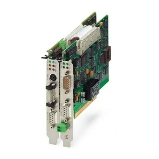
INTERBUS connections, the following section only describes the system coupler with an optical fiber connection (Order designation IBS PCI SC/RI-LK). Figure 3-1 IBS PCI SC/RI/I-T system coupler 6190_en_03 PHOENIX CONTACT... -
Page 28: Unpacking The System Coupler
Persons who handle the system coupler must protect it by observing the ESD instructions before packing or unpacking the system coupler, opening control boxes or control cabinets, and before touching the system coupler. PHOENIX CONTACT 6190_en_03... -
Page 29: Structure Of The System Coupler
Connection of the external 24 V supply voltage for the slave part Slave interface (Remote OUT, outgoing remote bus) Slave interface (Remote IN, incoming remote bus) Diagnostic LEDs (indicators) DIP switches for the slave configuration DIP switches for the master configuration 6190_en_03 PHOENIX CONTACT... -
Page 30: System Coupler Indicators
Host failure Host system failure; driver not yet started FAIL Failure Error has occurred in the INTERBUS system Yellow Peripheral failure Peripheral failure of an INTERBUS device Yellow Bus segment aborted One or more bus segments are disconnected PHOENIX CONTACT 6190_en_03... - Page 31 IBS PCI SC/RI-LK and IBS PCI SC/RI/I-T Hardware Installation Figure 3-3 Master board LED indicators 6190_en_03 PHOENIX CONTACT...
- Page 32 MAU warning occurs due to poor transmission quality on the path (this applies to the data forward path/transmitter for the following module, the state of the data return path/receiver is diagnosed from the following module). Figure 3-4 LED to diagnose the outgoing optical fiber interface PHOENIX CONTACT 6190_en_03...
- Page 33 IBS PCI SC/RI-LK and IBS PCI SC/RI/I-T Hardware Installation Slave Expansion Module The LED indicators on the slave expansion module provide information on the state of the higher-level INTERBUS system and the slave expansion module. Figure 3-5 Slave expansion module LED indicators 6190_en_03 PHOENIX CONTACT...
- Page 34 (this applies to the data forward path/transmitter for the following module, the state of the data return path/receiver is diagnosed from the following module). The FO1 and FO2 LEDs are not available on the system coupler with D-SUB interface (IBS PCI SC/RI/I-T). 3-10 PHOENIX CONTACT 6190_en_03...
-
Page 35: Serial Rs-232 Interface (Mini-Din Female Connector)3-11
IBS CMD SWT G4 E. In addition, the firmware of the controller board can be downloaded via the serial interface (RS-232). In this way, it is possible to meet future system requirements by means of updates. 3-11 6190_en_03 PHOENIX CONTACT... -
Page 36: Setting Up The System Coupler
The default value (upon delivery) is 1. If only one INTERBUS PCI board is used, the board number does not need to be changed. Figure 3-7 Default settings of the DIP switches (board number 1) 3-12 PHOENIX CONTACT 6190_en_03... - Page 37 Table 3-4 DIP switches for setting the board number Board Number DIP Switch 1 DIP Switch 2 DIP Switch 3 Default DIP switches 4, 5, 6, and 8 are reserved for extensions, and must not be changed. 3-13 6190_en_03 PHOENIX CONTACT...
-
Page 38: Dip Switch For Selecting The Baud Rate
"OFF") is 500 kbaud. Alternatively, 2 Mbaud (switch position "ON") can be set. Figure 3-8 DIP switch for selecting the baud rate With the IBS PCI SC/RI/I-T system coupler, the baud rate is selected automatically. Therefore DIP switch 7 does not have to be set. 3-14 PHOENIX CONTACT 6190_en_03... -
Page 39: Dip Switches For Setting Up The Slave Expansion Module
DIP switch 10 is in the "OFF" position. For further information on the system coupler configuration, please refer to Section 5 „Behavior of the IBS PCI SC/RI-LK and IBS PCI SC/RI/I-T System Couplers“. 3-15 6190_en_03 PHOENIX CONTACT... - Page 40 These DIP switches are also used to specify the length code. Table 3-6 Setting the process data length DIP Switches Process Data Length Code 0 words 1 word 2 words 3 words 4 words 5 words 6 words 7 words 8 words 3-16 PHOENIX CONTACT 6190_en_03...
- Page 41 If you change the configuration of the slave expansion module using DIP switches, the new configuration is only accepted once the slave expansion module, the master part, and the host system have been powered up simultaneously. 3-17 6190_en_03 PHOENIX CONTACT...
- Page 42 Therefore only set DIP switch 10 to the "ON" position when starting up your INTERBUS system or if, for example, you want to check the cabling. For normal operation it is recommended that DIP switch 10 is in the "OFF" position and configuration is carried out using software. 3-18 PHOENIX CONTACT 6190_en_03...
-
Page 43: Installing The System Coupler
24 V DC supply voltage. The power consumption of the slave expansion module is 3.5 W (typical). The supply voltage is connected with a 2-pos. MINI-COMBICON connector. Figure 3-10 Connecting the external voltage supply for the slave expansion module 3-19 6190_en_03 PHOENIX CONTACT... -
Page 44: Installing The System Coupler In The Pc
If only one PCI slot and another adjacent slot are free, the PCI system connector can be removed from the slave expansion module and the module can be mounted in the free slot. Ensure that the module is secure. 3-20 PHOENIX CONTACT 6190_en_03... - Page 45 PC casing. The PC casing must be grounded in compliance with the regulations. 6. Close the PC. 7. Plug in the PC and switch it on again. Now the system coupler is completely installed in your PC. 3-21 6190_en_03 PHOENIX CONTACT...
-
Page 46: Bus System Connection
"Remote OUT" indicates the connection for the outgoing remote bus of the slave interface. On the lower-level master "Remote OUT" indicates the master interface. Figure 3-12 Connecting the bus system via optical fibers 3-22 PHOENIX CONTACT 6190_en_03... - Page 47 Section This section informs you about – the driver installation. Software........................4-3 Installing the Driver for Windows NT 4.0........4-3 Installing the Driver for Windows 2000........4-6 Installing Additional Tools ............4-8 6190_en_03 PHOENIX CONTACT...
- Page 48 PHOENIX CONTACT 6190_en_03...
-
Page 49: Software
Microsoft Internet Explorer 5.5 from the "[drive:\IE55]" directory of the CD. 1. Insert the CD with the driver for Windows NT 4.0. The CD starts automatically. Figure 4-1 Start page of the IBS PCI SC CD-ROM 2. Now select the language. 6190_en_03 PHOENIX CONTACT... - Page 50 To install the driver and other tools, select "Run this program from its current location" in the "File Download" dialog box. 4. Driver installation is now completed. Figure 4-3 Driver setup for the IBS PCI MPM driver PHOENIX CONTACT 6190_en_03...
- Page 51 Information on this can be found in "DIP Switches for Setting the Board Number" on page 2-8 and page 3-12. 6. Restart the computer. If you want to change the driver settings, restart the driver setup. 6190_en_03 PHOENIX CONTACT...
-
Page 52: Installing The Driver For Windows 2000
If the hardware assistant is not activated automatically after having installed a PCI controller board or a PCI system coupler you can start the hardware assistant from the Windows 2000 system control. Figure 4-4 Windows 2000 control panel PHOENIX CONTACT 6190_en_03... - Page 53 Number" on page 2-8 and page 3-12. The include and header files from the "[Drive:\install\driver\win2000\ddi]" directory must be copied manually into the appropriate directory because the driver for Windows 2000 will be installed with the help of the hardware assistant. 6190_en_03 PHOENIX CONTACT...
-
Page 54: Installing Additional Tools
IBS CMD SWT G4 E software (Order No. 27 21 44 2) and the INTERBUS OPC server IBS OPC SERVER (Order No. 27 29 12 7) can be ordered from Phoenix Contact. Complete documentation for the controller boards is also available in pdf format on the IBS PCI SC CD-ROM, in the "Documentation"... - Page 55 Starting Up With Parameterization of the Master...5-6 5.1.4 Changing the Configuration Using Firmware Services ..5-7 5.1.5 Changing the Configuration Using IBS CMD SWT G4 E..........5-13 System Behavior and Diagnostics ..........5-14 5.2.1 Reset Behavior ............5-14 5.2.2 Message Behavior ............5-15 5.2.3 Data Behavior ..............5-16 6190_en_03 PHOENIX CONTACT...
- Page 56 PHOENIX CONTACT 6190_en_03...
-
Page 57: Behavior Of The Ibs Pci Sc/Ri-Lk And Ibs Pci Sc/Ri/I-T System Couplers
INTERBUS system. The data transmission rate is 500 kbaud and the I/O error message is active if the power for the master board fails. The following diagram shows the basic sequence when starting the system couplers: 6190_en_03 PHOENIX CONTACT... - Page 58 IBS PCI SC QS UM E Figure 5-1 Startup behavior of the system couplers PHOENIX CONTACT 6190_en_03...
-
Page 59: Starting Up Without Parameterization Of The Master
INTERBUS system is not ready-to-operate. Now the system coupler can be parameterized and configured by the higher-level INTERBUS system or the host system. This can be done using firmware services or IBS CMD SWT G4 E software. 6190_en_03 PHOENIX CONTACT... -
Page 60: Starting Up With Parameterization Of The Master
INTERBUS systems (see "Master startup"). PHOENIX CONTACT 6190_en_03... -
Page 61: Changing The Configuration Using Firmware Services
A detailed description of the firmware services can be found in the "Firmware Services and Error Messages" User Manual (IBS SYS FW G4 UM E, Order No. 27 45 18 5), which is part of the System Manual. 6190_en_03 PHOENIX CONTACT... - Page 62 Bit 0 corresponds to DIP 1 Process data length Bit 1 corresponds to DIP 2 Bit 0 corresponds to DIP 7 Reporting I/O errors and 011D Bit 1 corresponds to DIP 8 setting the baud rate Bit 2 corresponds to DIP 9 PHOENIX CONTACT 6190_en_03...
- Page 63 The number of system parameters to which new values are to be assigned Variable_ID: ID of the system parameter to which new values are to be assigned (see Table 5-1) Value: The new value of the system parameter 6190_en_03 PHOENIX CONTACT...
- Page 64 The controller board executed the service successfully. xxxx Indicates a negative message. The controller board could not execute the service successfully. The Result parameter indicates why the service could not be executed. Add_Error_Info: Additional information on the error cause 5-10 PHOENIX CONTACT 6190_en_03...
- Page 65 Key: Code: 0351 Command code of the service request Parameter_Count: Number of subsequent words xxxx = 1 + Variable_Count Variable_Count: Number of system parameters to be read Variable_ID: ID of the system parameter to be read 5-11 6190_en_03 PHOENIX CONTACT...
- Page 66 The length of the system parameter (16 words, maximum) is specified in the third hexadecimal position (bits 8 ... 11) of the Variable_ID parameter. with a negative message: 0002 2 parameter words 5-12 PHOENIX CONTACT 6190_en_03...
-
Page 67: Changing The Configuration Using Ibs Cmd Swt G4 E
The "Parameterization Memory... Save ..." function can then be used to send the configuration to the system coupler and store it as the default configuration. For detailed information on operation of IBS CMD SWT G4 E, please refer to the online help. 5-13 6190_en_03 PHOENIX CONTACT... -
Page 68: System Behavior And Diagnostics
PC. To do this, the diagnostic status register and the diagnostic parameter register of the master must be assigned to addresses in the same memory and these addresses must be accessed using the slave input data. 5-14 PHOENIX CONTACT 6190_en_03... -
Page 69: Message Behavior
The master part reports a controller error, the watchdog or SysFail is triggered, and communication with the host is interrupted by the module. If you want to report other states you can map them to the host system using the application program. 5-15 6190_en_03 PHOENIX CONTACT... -
Page 70: Data Behavior
IBS PCI SC QS UM E 5.2.3 Data Behavior Alarm Stop in the Lower-Level INTERBUS System In the event of an alarm stop in the lower-level INTERBUS system, the process data to the higher-level master (slave output data) is reset. 5-16 PHOENIX CONTACT 6190_en_03... -
Page 71: A Technical Appendix
Reads the slave diagnostic register DDIGetInfo Reads the driver version (Windows NT) * Messages corresponding to the firmware commands for the control and parameterization of INTERBUS or PCP (Peripheral Communication Protocol) to intelligent devices in the INTERBUS system. 6190_en_03 PHOENIX CONTACT... -
Page 72: Comparison Of Polymer Fibers And Hcs Fibers
IEC 874-2 (St.6/89) according to IEC 874-2 (St.6/89) DIN 47258 (St. E 11/89) DIN 47258 (St. E 11/89) Phoenix Contact offers pre-assembled bus cables to minimize assembly times. The cables are available in various lengths. PHOENIX CONTACT 6190_en_03... -
Page 73: Ibs Pci Sc/I-T Technical Data
Operation: 860 hPa to 1080 hPa (up to 1500 m [4921 ft.] above sea level) Storage and transport: 660 hPa to 1080 hPa (up to 3500 m [11483 ft.] above sea level) Vibration 2g, criterion 1 according to IEC 68-2-6 6190_en_03 PHOENIX CONTACT... - Page 74 Criterion B IEC 61000-4-5: 1995 Signal/data lines: 1 kV Conducted interference EN 61000-4-6 Criterion A IEC 61000-4-6: 1996 Test voltage 10 V Noise Emission Test According to EN 55011 (Industrial Area) Emitted interference EN 55011 Class A PHOENIX CONTACT 6190_en_03...
-
Page 75: Ibs Pci Sc/Ri-Lk Technical Data
256-kbyte memory window Connection method Direct edge connection Remote Bus Interfaces Connection method Optical fiber, 2 F-SMA connectors according to IEC 874-2 Diagnostic Interface Connection method 6-pos. Mini-DIN female connector (PS/2) Interface type RS-232 Transmission rate 9600 baud 6190_en_03 PHOENIX CONTACT... - Page 76 Criterion B IEC 61000-4-5: 1995 Signal/data lines: 1 kV Conducted interference EN 61000-4-6 Criterion A IEC 61000-4-6: 1996 Test voltage 10 V Noise Emission Test According to EN 55011 (Industrial Area) Emitted interference EN 55011 Class A PHOENIX CONTACT 6190_en_03...
-
Page 77: Ibs Pci Sc/Ri/I-T Technical Data
Edge connection Remote Bus Interfaces Connection method 9-pos. D-SUB female connector Interface type RS-422 Electrical isolation Yes (test voltage 0.5 kV) Diagnostic Interface Connection method 6-pos. Mini-DIN female connector (PS/2) Interface type RS-232 Transmission rate 9600 baud 6190_en_03 PHOENIX CONTACT... - Page 78 Criterion B IEC 61000-4-5: 1995 Signal/data lines: 1 kV Conducted interference EN 61000-4-6 Criterion A IEC 61000-4-6: 1996 Test voltage 10 V Noise Emission Test According to EN 55011 (Industrial Area) Emitted interference EN 55011 Class A PHOENIX CONTACT 6190_en_03...
-
Page 79: Ordering Data
IBS SYS PRO INST UM E 27 43 80 2 Manual IBS CMD SWT G4 E operating software IBS CMD SWT G4 E 27 21 44 2 INTERBUS OPC server IBS OPC SERVER 27 29 12 7 6190_en_03 PHOENIX CONTACT... - Page 80 Appendix A-10 PHOENIX CONTACT 6190_en_03...
Need help?
Do you have a question about the AUTOMATIONWORX IBS PCI SC/I-T and is the answer not in the manual?
Questions and answers