
Related Manuals for Regulus BIO 55 MIX W-PWM 1F TRS6K


Summary of Contents for Regulus BIO 55 MIX W-PWM 1F TRS6K
- Page 1 Installation and Operation Manual BIO 55 MIX W–PWM 1F TRS6K LOAD UNIT BIO 55 MIX W–PWM 1F TRS6K VARIANT 1A VARIANT 1B VARIANT 1C VARIANT 2...
-
Page 2: Table Of Contents
CONTENTS Safety Instructions .................... Safety Instructions .................... B.1. Load Unit Components ................B.2. Load Unit Data ..................B.3. Pressure Drop Graph ................B.4. Dimensions ....................Load Unit Installation ..................C.1. Hydraulic Connection of the Load Unit ............C.2. Overview of Basic Hydraulic Variants ............C.2.1. -
Page 3: Safety Instructions
(e.g. electric heating element) must be disconnected from the power supply! ● The BIO 55 MIX W-PWM 1F TRS6K load unit is in no way a replacement for the safety components of the heating system, hot water system and boiler. These safety elements must always be installed in accordance with the applicable standards and regulations. -
Page 4: Load Unit Components
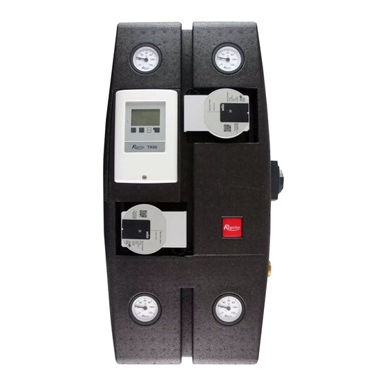
B.1. LOAD UNIT COMPONENTS 1 – 4m cable with Pt 1000 temperature sensor 2 – Power cord 3 – Boiler return line thermometer 4 – Wilo Para 25/8 iPWM1 boiler pump 5 – TRS6 BIOMIXK Controller 6 – Return heating water thermometer 7 –... -
Page 5: Load Unit Data
B.2. LOAD UNIT DATA Technical Data Fluid working temperature 5-95 °C 6 bar Max. working pressure Min. working pressure 0.5 bar Ambient temperature 5-40 °C max. 80 %, non condensing Max. relative humidity Max. temperature of sheath sensors 95 °C 55 °C Min. -
Page 6: Pressure Drop Graph
B.3. PRESSURE DROP GRAPH BOILER SIDE Q [m HEATING CIRCUIT Q [m PERFORMANCE CURVES FOR WILO PARA 25/8 iPWM1 PUMP for various % of PWM control signal │... -
Page 7: Dimensions
B.4. DIMENSIONS Note: The dimensional diagram of the open load unit is rotated for illustrative purposes, the outlets for the thermal store connection are mutually aligned (see side view). C. LOAD UNIT INSTALLATION The load unit is designed for wall mounting. It shall be mounted in the selected position using the enclosed installation kit. - Page 8 Procedure for conversion of the load unit to connect the thermal store from the right Loosen the nut and remove the extension Remove the top part of insulation. for the outlet to the thermal store (this will be used in step 8). On the right and left side of the insulation body there are insulated passage points Loosen the nut and turn the elbow to...
- Page 9 Assemble the elbow with the extension Loosen the elbow and take it out of the removed in step 3 and re-install it to load unit. same location so that the outlet now points to the right. Mount the pump back to its original Replace all the remaining pieces of place, tighten both nuts and return back insulation to their original places.
-
Page 10: Hydraulic Connection Of The Load Unit
C.1. HYDRAULIC CONNECTION OF THE LOAD UNIT HOW TO PROCEED: Make hydraulic connections of the boiler, heating system, thermal store(s) or hot water tank(s) with the load unit, respecting the selected hydraulic variant (see the following pages) → Fill and air bleed the system → Perform a pressure test → Place temperature sensors to the respective sheaths depending on the selected hydraulic variant →... -
Page 11: Overview Of Basic Hydraulic Variants
C.2. OVERVIEW OF BASIC HYDRAULIC VARIANTS These basic diagrams can be extended with accessories that can always be found after the respective diagram on the following pages. C.2.1. Variant 1, Option A A system with a solid fuel boiler w. manual stoking, one heating circuit and a combination thermal store. - Page 12 Basic hydraulic diagram DESCRIPTION ball valve RegulusBIO Load Unit check valve boiler drain valve combination thermal store with DHW REDV pressure reducing valve (5 bar) heating system expansion vessel service valve safety kit* DOCHV thermal safety relief valve (e.g. BVTS) *the safety kit involves a test valve, check valve, drain valve, safety valve, TSV TV...
- Page 13 OPTIONAL ACCESSORIES FOR HYDRAULIC VARIANT 1, OPTION A Caleon Room Unit Room Temperature Sensor For comfortable and more precise room For more precise room temperature control temperature control Caleon room unit w. touchscreen and temperature sensor (code Room temperature 17150). sensor in ABB TIME design (code 16167).
-
Page 14: Variant 1, Option B
C.2.2. Variant 1, Option B A system with a solid fuel boiler w. manual stoking, one heating circuit, a combination thermal store and a thermal store. The BIO MIX Load Unit ensures DHW and space heating and heat storage in the combination and standard thermal stores. It is recommended to use a Caleon room unit or a room temperature sensor for a more precise control of the room temperature. - Page 15 OPTIONAL ACCESSORIES FOR HYDRAULIC VARIANT 1, OPTION B Caleon Room Unit Room Temperature Sensor For comfortable and more precise room For more precise room temperature control temperature control Caleon room unit w. touchscreen and temperature sensor (code Room temperature 17150). sensor in ABB TIME Caleon Wifi room unit design (code 16167).
-
Page 16: Variant 1, Option C
C.2.3. Variant 1, Option C A system with a solid fuel boiler w. manual stoking, one heating circuit and a thermal store. The BIO MIX Load Unit ensures space heating and heat storage in the thermal store. It is recommended to use a Caleon room unit or a room temperature sensor for a more precise control of the room temperature. - Page 17 OPTIONAL ACCESSORIES FOR HYDRAULIC VARIANT 1, OPTION C Caleon Room Unit Room Temperature Sensor For comfortable and more precise room For more precise room temperature control temperature control Caleon room unit w. touchscreen and temperature sensor (code Room temperature 17150). sensor in ABB TIME Caleon Wifi room unit design (code 16167).
-
Page 18: Variant 2
C.2.4. Variant 2 A system with a solid fuel boiler w. manual stoking, one heating circuit, a thermal store and a hot water storage tank. The BIO MIX Load Unit ensures space and DHW heating and heat storage in the thermal store. It is recommended to use a Caleon room unit or a room temperature sensor for a more precise control of the room temperature. - Page 19 NECESSARY ACCESSORIES FOR HYDRAULIC VARIANT 2 Temperature sensor for thermal store Lower temperature sensor for thermal store (to be ordered separately, code 9109). For installation description see Chapter D.7. Heat transfer pump station A heat transfer pump station ensures heating of the hot water storage tank (by drawing heat from the thermal store).
-
Page 20: Accessory Installation
D. ACCESSORY INSTALLATION If you do not intend to install any accessories, proceed directly to the controller settings. INSTRUCTIONS FOR ELECTRICAL WIRING AND ACCESSORY SETTINGS Electrical wiring of the accessories must be carried out by a person qualified according to the applicable standards and regulations. -
Page 21: Rc Caleon & Rc Caleon Wifi Room Units
ACCESSORY INSTALLATION D.1. RC CALEON & RC CALEON WIFI ROOM UNITS The Caleon unit is equipped with a colour touch screen that allows you to easily perform all user settings. It includes a room temperature sensor that allows for more precise control. It displays temperature and humidity in the room as well as Description the outside temperature (the reading is taken from the outdoor... -
Page 22: Room Temperature Sensor
D.2. ROOM TEMPERATURE SENSOR The room temperature sensor allows for more precise control of the room temperature. Description It shall be ordered separately, code 16167, and it is an alternative to the Caleon room unit. Intended for variants 1 (options A, B, C) It shall be installed on a wall in a reference room at a height of 1.2 to 1.6 m above the floor, out of direct sunlight and far Installation... -
Page 23: Electric Heating Element For Dhw Afterheating
Heating elements are available in various designs and outputs, the current assortment can be found on our website: https://www. Description regulus.eu/en/ett-g-6-4-for-hw-storage-tanks-and-thermal- stores. The recommended model is ETT M that is equipped with an integrated adjustable and safety thermostat and a power cord w. -
Page 24: Electric Heating Element For Dhw Afterheating
Ripple control, e.g. ETT L series. Heating elements are available in various designs and outputs, the current assortment can be found on our website: https://www. regulus.eu/en/ett-g-6-4-for-hw-storage-tanks-and-thermal-stores. Intended for variants 1 (options A, B, C) Into the E2/E3 connection of a DUO/HSK combination thermal Installation store or into any connection of a thermal store. - Page 25 Wiring diagram of ETT L heating element without blocking by Ripple control: Wiring diagram located on the top cover of the printed circuit board POWER SUPPLY EXTRA LOW VOLTAGE heating element terminal board controller terminal board TIP 1: The heating element can be used also for DHW heating in combination thermal stores (variants 1A and 1B), supposed the terminal S1 is not occupied by an optional room temperature sensor (Caleon room unit can be used).
-
Page 26: Dhw Recirculation Pump
D.5. DHW RECIRCULATION PUMP If you do not intend to control a heating element for space heating by the controller, the controller can be used for switching hot water recirculation following a time program. Description It is recommended to use a pump station for DHW recirculation with integrated anti-scald valve CSE TVMIX ZV G 3/4M (code 17893 –... -
Page 27: Heat Transfer Pump
D.6. HEAT TRANSFER PUMP Hot water heating in an external HW storage tank is ensured by pumping hot water from the thermal store to an integrated heat exchanger in the HW storage tank. Heat transfer is controlled by the TRS6K controller integrated in the BIO load unit. Description For hot water pumping it is necessary to install a circulation pump and a check valve that will prevent gravity circulation. -
Page 28: Temperature Sensor In Thermal Store
D.7. TEMPERATURE SENSOR IN THERMAL STORE The lower temperature sensor in the thermal store is used for speed control of the boiler circulation pump. The controller adjusts the speed of the boiler circulation pump to the boiler output with Description the aim to keep optimal temperature distribution in the thermal store and at the same time to avoid boiler overheating. -
Page 29: System Settings
E. SYSTEM SETTINGS To set up the system correctly, we recommend using the Setup Wizard when starting the controller for the first time. Then it is advisable to browse through the following chapters and make further setting adjustments if needed. E.1. -
Page 30: Setup Wizard
E.2. SETUP WIZARD The setup wizard guides you through the necessary basic settings in the correct order, and provides brief descriptions of each parameter in the display. Pressing the “esc” key takes you back to the previous level so you can look at the selected setting again or adjust it if desired. Pressing the “esc“... - Page 31 SETTING A SIMPLE HEATING CURVE 5. Heating curve Select the heating curve “simple” and confirm by pressing OK button. 6. Heating curve inclination The default inclination is 0.8 which corresponds to the outlet temperature of 46 °C at the outdoor temperature of -12 °C.
- Page 32 SETTING A SPLIT HEATING CURVE Heating curve Select the type “split” and confirm by pressing OK button. Typical values for underfloor heating (design temperature drop 42 °C / 35 °C), low-temperature radiators (design temperature drop 55 °C / 45 °C) and high-temperature radiators (design temperature drop 70 °C / 55 °C) are shown here as examples.
-
Page 33: Free Commissioning
E.3. FREE COMMISSIONING If you decide not to use the commissioning help, you should do the necessary settings in the following sequence: • menu 10. Language • menu 3.1. Time and Date • menu 7.1. Program Selection • menu 5. Settings, all values. •... -
Page 34: General Settings
E.4. GENERAL SETTINGS 3.1. Time & Date In the event of a power failure, check the time on the controller. If the power failure lasts more than 24 hours, the clock in the controller will stop. 3.2. Daylight saving time Setting of an automatic change to and from DST. - Page 35 Room temperature settings (Only with a room unit or sensor installed) Room temperatures for time program 3.3 can be set in menus: 5.1.19.2. Room Reference (Day) The desired room temperature for day mode. 5.1.19.3. Room Reference (Night) The desired room temperature for night mode. 5.1.15.
- Page 36 Heating circuit 5.1.1. Operating mode of the heating circuit It is recommended to keep the Heating mode setting. 5.1.2. Summer/Winter day Here the outdoor temperature is set for automatic transition between the Winter and Summer modes in the Day mode. (Note: the Summer mode will switch off heating.) 5.1.3.
- Page 37 Meanwhile, the heated water from the boiler gradually fills the pipes and the upper part of the thermal store. When the temperature at the upper sensor of the thermal store reaches the set value, the heating system pump is activated and pumps the heated water into the heating system.
- Page 38 Boiler settings 5.11.1. Max. temperature of hot water storage tank (Storage tank Tmax)) Max. temperature at the storage tank sensor (5.11.6.). Above this value, the boiler pump remains always off. 5.11.2. Min. boiler temperature (Tmin SF) Min. temperature at the boiler sensor (5.11.5.) to switch the boiler pump on. If the temperature is below this value, the boiler pump is always off.
-
Page 39: Auxiliary Heat Source (El. Heating Element)
E.6. AUXILIARY HEAT SOURCE (EL. HEATING ELEMENT) OPTIONAL ACCESSORY (NOT REQUIRED) For Variant 1 (options A, B, C) only Menu for an aux. heat source (el. heating element) is available when the system configuration “1 (Combi+HC+SF)” is selected. The auxiliary heat source is switched on when there is a demand to heat up the thermal store (a request from a heating circuit). -
Page 40: Dhw Recirculation Pump
E.7. DHW RECIRCULATION PUMP OPTIONAL ACCESSORY (NOT REQUIRED) This cannot be used together with an electric heating element controlled by the controller. If you require using both a circulation pump and an electric heating element, you can either use an el. heating element controlled by its integrated adjustable thermostat, or control the circulation pump by an external time switch. -
Page 41: Complete Controller Menu
E.8. COMPLETE CONTROLLER MENU In this chapter you will find an overview of all functions of the BIO MIX controller. The controller is factory preset for the most common heating system configurations with the BIO MIX load unit. Some functions may require the purchase of additional accessories or may not be usable. List of controller menu chapters: 1. - Page 42 1. Measurement Values Menu “1. Measurement Values” is intended to display the current measured temperatures. The selected program and the specific controller model determine which measurement values are displayed. The menu is closed by pressing “esc” or selecting “Exit measurements”. If “---”...
- Page 43 3. Periods Menu 3. Periods contains settings for time, date and operating times for the heating circuit. The menu is closed by pressing “esc” or selecting “Exit periods”. The associated temperature reference values are specified in Menu 5. Settings. 3.1. Time & Date This menu is used to set the current time and date.
- Page 44 4. Operating Mode of the Controller Menu “4. Operating Mode” can be used to switch the controller to automatic mode, turn it off, or switch to manual mode. The menu is closed by pressing “esc” or selecting “Exit operating mode”. 4.1.
- Page 45 5.Settings In Menu “5. Settings” the system parameters are set. The menu is closed by pressing “esc” or selecting “Exit settings”. By no means does the controller replace any safety elements in a heating circuit, DHW circuit, solar circuit and in electric devices of a heating system! 5.1.
- Page 46 5.1.5. Heating curve The weather compensating curve is used to control the heat dissipation of the heating circuit relative to the outdoor temperature. The curve can be set either as simple, or as split that is divided by a slope change point into two parts. The simple curve can be set using one parameter.
- Page 47 5.1.10. Maximum flow (Tmax) The maximum flow temperature. When exceeded, the heating circuit pump will be switched off and not started again until the temperature falls below this value. Limiting the max. flow temperature does not replace a high limit thermostat that shall be connected to the pump power cable in systems that require safe limiting the max.
- Page 48 5.1.17. Thermal inertia of a building Thermal inertia of a building indicates how fast the calculated desired heating water temperature (following the heating curve) is influenced by a change in outdoor temperature. The heavier the building design, the more slowly can be the heating water temperature modified through the outdoor temperature.
- Page 49 5.1.21. PV contact 1 This sensor input could be used as a PV-contact to signal overflow from a Photovoltaic System. If the PV-Contact set in this menu is closed, the heating circuit is set to Daytime mode. For info on the operation and wiring of the PV contact please consult the technical manual of your PV system.
- Page 50 5.3.6. Buffer DHW load The DHW heating from the thermal store is turned on at an active heat request for DHW and if the temperature at the thermal store sensor is at least 8°C higher than at the DHW sensor. The DHW heating from the thermal store is shut down if the temperature difference between the thermal store and HW storage tank is less than 4 °C or if the temperature at the DHW sensor has reached the desired value and no DHW heat request is present.
- Page 51 5.5.5. Max. temperature of a heat consumer (Tmax DF-Drain) Max. temperature at the heat consumer sensor for switching off the differential thermostat function. If the temperature at the consumer sensor is higher than DF-Drain, the differential thermostat output contacts will not close. 5.6.
- Page 52 5.8.3. Temperature to switch on an aux. heat source (TH Set) Preset temperature to switch on an aux. heat source (e.g. an electric heating element). The heat source will switch on when the temperature at the reference sensor (depending on the active request) drops below this value.
- Page 53 5.12.4. Starting aid This function is not used for Regulus solar collectors. For some solar thermal systems, in particular for evacuated tube collectors, the measurement recording on the collector sensors may be too slow or imprecise, because the sensor is often not on the warmest spot.
- Page 54 If the collector temperature exceeds the value “Frost level 2” by 2 °C, the pump will turn off again. Energy is lost through the collector through this function! Regulus solar thermal system use antifreeze fluid only and the frost protection is off.
- Page 55 5.17.1. DHW request The Boiler (Burner) function will be activated only when there is an active demand for DHW heating (the measured DHW temperature has dropped below the currently desired value following the set DHW temperatures and periods – see menu 5.3.). 5.17.2.
- Page 56 5.22.2. Temperature difference to switch on and off the return flow increase (Δt on / Δt off) A temperature difference between the storage sensor (5.22.4.) and the heating return flow sensor (5.22.3.) to switch on (Δt on) and off (Δt off) the return flow increase function. 5.22.3.
- Page 57 5.24.2. Reference humidity Max. humidity to switch on the dehumidifier function. The function will be switched on depending on the active operating mode if the actual humidity is higher than the set value. 5.24.3. Hysteresis to switch off the dehumidifier Hysteresis to switch off the dehumidifier.
- Page 58 6. Protective Functions In Menu 6. Protections the system protective functions are set and activated. The menu is closed by pressing “esc” or selecting “Exit protections”. By no means does the controller replace the safety appliances on site! 6.1. Seizing Protection If the anti-seizing protection is activated, the controller switches gradually all outputs at 12:00 noon for 5 seconds to prevent seizing of the pump/valve after long periods of inactivity.
- Page 59 7. Special Functions In Menu 7. Special Functions the basic controller settings and expanded functions are set. The menu is closed by pressing “esc” or selecting “Exit Special Functions”. The settings in this menu should only be changed by a specialist. 7.1.
- Page 60 7.2.6. PWM / 0-10V max. (default setting is “7%”) Setting the head of the heating circuit pump. The lower the PWM value, the higher the head – see the values in the table. Head [m] PWM maximum [%] 7.2.7. Show signal Represents the set pump signal in a graphic and text overview.
- Page 61 7.5.4. Max. speed (default setting is “100%”) The maximum speed of the pump for speed control variants is determined here. It is not recommended to limit the head of the pump, as this could cause boiler overheating. The controller controls the pump automatically at optimum speed. The indicated percentages are informative values that may vary to a greater or lesser extent depending on the system, pump and pump stage.
- Page 62 7.7.2.5. Increase (default setting is “0”) If the temperature drops very fast, this value is subtracted from the measured flow temperature so that the mixer’s reaction is stronger. If the measured temperature does not drop any more, the measured value is used again. The measurement occurs once every minute. These settings are only necessary in special cases at the time of initial commissioning by the specialist.
- Page 63 7.9.17. Dehumidifier Dehumidifier settings are described in Chap. 5.24. 7.9.18. Parallel operation The function switches parallel to the set signal output – both the outputs switch in parallel. The function can be inverted, so the output switches contrary to the set signal output. 7.9.18.2.
- Page 64 7.15. Network The CAN bus setup menu requires the installation of a datalogger (not included) for data logging and internet access. For internet access for setting common user parameters (temperatures, time programs, etc.) we recommend using the more user-friendly Caleon WiFi. 7.15.1.
- Page 65 8. Menu Lock Menu „8. Menu lock” can be used to secure the controller against unintentional changing the set values. The menu is closed by pressing “esc” or selecting “Exit menu lock”. The menu lock represents a feature securing the controller against unintentional changing the set values.
- Page 66 9. Service values The menu “9. Service values” can be used for remote diagnosis by a specialist in the event of an error etc. Enter the values into the table when an error occurs. The menu can be closed by pressing “esc”. 9.1.
- Page 67 10. Language Menu “10. Language” is used to select the language for the menu guidance. This is queried automatically during initial commissioning. │...
-
Page 68: Servicing, Maintenance
3 (NO closing contact) ON PRINTED CIRCUIT BOARD CAN1 connection of CAN bus (1=high, 2=low) for Caleon room units CAN2 connection of CAN bus (1=high, 2=low) for Caleon room units VFS1 not used in Regulus systems VFS2 not used in Regulus systems │... -
Page 69: Status Indication And Error Messages
F.2. STATUS INDICATION AND ERROR MESSAGES The status is signalled by the LED light that • is lit green – when a relay is switched on • is lit red - when Auto mode is set and all relays are off •... -
Page 70: Replacing The Controller Fuse
F.3. REPLACING THE CONTROLLER FUSE If the mains voltage is switched on and the controller still does not function or display anything, then the internal device fuse may be defective. In such a case check the fuse and, if needed, replace it. -
Page 71: Servicing & Maintenance Of Hydraulic Components
F.4. SERVICING & MAINTENANCE OF HYDRAULIC COMPONENTS BOILER AND HEATING CIRCUIT PUMPS The operating status and possible pump faults are displayed by LED indication directly on the pump. LED indication State description and possible fault reasons green is lit – pump is running in trouble-free operation –... -
Page 72: Legislation
The crossed out wheeled bin with marking bar, printed ether in the Manual or on the product itself, identifies that the product must be disposed of at a recycling collection site. v1.8-09/2021 ©2021 We reserve the right to errors, changes and improvements without prior notice software v15996-05/2021 REGULUS spol. s r.o. E-mail: sales@regulus.eu Web: www.regulus.eu...
Need help?
Do you have a question about the BIO 55 MIX W-PWM 1F TRS6K and is the answer not in the manual?
Questions and answers