Regulus CSE2 MIX-BP F G60 1F Installation And Operation Manual
Pump station
Hide thumbs
Also See for CSE2 MIX-BP F G60 1F:
- Installation and operation manual (20 pages) ,
- Installation and operation manual (20 pages) ,
- Installation and operation manual (20 pages)

Related Manuals for Regulus CSE2 MIX-BP F G60 1F


Summary of Contents for Regulus CSE2 MIX-BP F G60 1F
- Page 1 Installation and Operation Manual CSE2 MIX-BP F G60 1F PUMP STATION CSE2 MIX-BP F G60 1F...
-
Page 2: Table Of Contents
MIXING VALVE ..................3.3. CHECK VALVE ..................3.4. FILTER WITH MAGNET ................3.5. BALL VALVES ................... PUMP STATION CONNECTION DIAGRAM ............PUMP STATION INSTALLATION ............... TEMPERATURE SENSOR INSTALLATION ............OPTIONAL ACCESSORIES ................Regulus CSE2 MIX-BP F G60 1F - www.regulus.eu │... -
Page 3: Introduction
(125 mm pitch) Connections 4 x G 1“ F Code 19111 Data for CSE2 MIX-BP F G60 1F Pump Station Fluid working temperature 5 - 95 °C Max. working pressure 10 bar Min. working pressure 0.5 bar... -
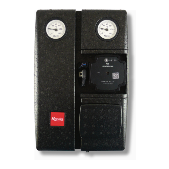
Page 4: Pump Station Components
7 – Lever for ball valves 8 – Ball valve w. sheath for temperature sensor (at return piping from heating circuit) 9 – Ball valve w. sheath for temperature sensor (at flow piping to heating circuit) Regulus CSE2 MIX-BP F G60 1F - www.regulus.eu │... -
Page 5: Grundfos Upm3 Auto 25-60 Pump
- not used in this pump Pump Control The circulation pump be controlled by selecting a suitable profile and a pump perfor- mance curve. Pump Performance Curves Line type Profile Constant speed Proportional pressure Constant pressure Regulus CSE2 MIX-BP F G60 1F - www.regulus.eu │... - Page 6 • Pump operating point: moves on the selected constant pressure curve depending on the current system pressure drop. PROFILE Max. H (upper graph) Max. P (lower graph) 25 W Constant 33 W speed 39 W Regulus CSE2 MIX-BP F G60 1F - www.regulus.eu │...
- Page 7 Pump profiles can be switched using the ointegrated button. Profile switching follows in a loop in the order shown in the table. Error display DISPLAY CONTROL MODE Seized pump Too low power supply voltage Electric fault Regulus CSE2 MIX-BP F G60 1F - www.regulus.eu │...
-
Page 8: Mixing Valve
The filter cap needs to be unscrewed, the metal strainer removed and rinsed thoroughly from any dirt. Dirt trapped on the magnet must be wiped off and then reassembled by inserting the strainer, screwing in and tightening the cap. Regulus CSE2 MIX-BP F G60 1F - www.regulus.eu │... -
Page 9: Ball Valves
As a result, unintentional closure of the system by an unauthorized person is not possible. OPEN CLOSED groove in the flow direction groove perpendicular to the flow direction Regulus CSE2 MIX-BP F G60 1F - www.regulus.eu │... -
Page 10: Pump Station Connection Diagram
PUMP STATION CONNECTION EXAMPLES Regulus CSE2 MIX-BP F G60 1F - www.regulus.eu │... - Page 11 Regulus CSE2 MIX-BP F G60 1F - www.regulus.eu │...
-
Page 12: Pump Station Installation
Pump station permitted and prohibited positions Permitted positions Conditionally permitted positions Prohibited positions (may be used if the filter is replaced by a filter replacement section, code 19017) Regulus CSE2 MIX-BP F G60 1F - www.regulus.eu │... -
Page 13: Temperature Sensor Installation
Temperature sensor placement Securing the temperature sensor with the screw Running the sensor cable through the recess in the insulation Regulus CSE2 MIX-BP F G60 1F - www.regulus.eu │... - Page 14 Trimming the cable passage lock Installed sensors Regulus CSE2 MIX-BP F G60 1F - www.regulus.eu │...
-
Page 15: Optional Accessories
The following optional accessories are available for the pump station: A – Filter replacement section for CSE2 Code 19017 Loosen the union nut above and below Remove the filter and install the the filter. replacement piece 19017 in its place. Regulus CSE2 MIX-BP F G60 1F - www.regulus.eu │... - Page 16 1“ Fu/M, incl. gasket Code 15695 Remove both connecting fittings. Install the unions 15695 in their place and the ball valve with drain valve 17415 onto each of them. Regulus CSE2 MIX-BP F G60 1F - www.regulus.eu │...
- Page 17 Code 18797 Remove both connecting fittings. Install the extended union w. check valve, code 18653, to the return pipe. Install the extended union w. check valve, code 18797, to the flow pipe. Regulus CSE2 MIX-BP F G60 1F - www.regulus.eu │...
- Page 18 D – Union for connecting CSE2 to 5/4“ manifold - 1“x5/4“ Fu/F Code 17920 Remove both connecting fittings. Install the union for connection to a manifold, code17920, instead of the original fittings. Regulus CSE2 MIX-BP F G60 1F - www.regulus.eu │...
- Page 19 Regulus CSE2 MIX-BP F G60 1F - www.regulus.eu │...
- Page 20 ©2022 We reserve the right to errors, changes and improvements without prior notice. REGULUS spol. s r.o. E-mail: sales@regulus.eu Web: www.regulus.eu...
Need help?
Do you have a question about the CSE2 MIX-BP F G60 1F and is the answer not in the manual?
Questions and answers