
Related Manuals for Regulus BIO 55 MIX W–PWM 1F TRS6K


Summary of Contents for Regulus BIO 55 MIX W–PWM 1F TRS6K
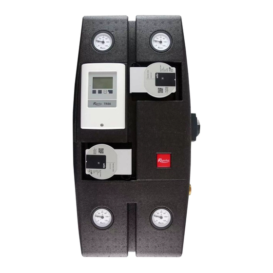
- Page 1 Installation and Operation Manual BIO 55 MIX W–PWM 1F TRS6K LOAD UNIT BIO 55 MIX W–PWM 1F TRS6K...
-
Page 2: Table Of Contents
DHW Recirculation Pump Settings (code 15181) ........9.3. Auxiliary Electric DHW Heating Element Settings (code 15169) ....9.4. RC Caleon Room Unit Settings (code 17150) .......... Attachment – Load Unit Rearrangement Procedure ............. Regulus BIO 55 MIX W–PWM 1F TRS6K - www.regulus.eu │... -
Page 3: Introduction
2 x G 1/2“ F alternative outlets to connect optional accessories (if you do not need to use the outputs, they can be plugged with the enclosed plugs) Code 17499 Regulus BIO 55 MIX W–PWM 1F TRS6K - www.regulus.eu │... -
Page 4: Load Unit Data
16.7 kg * the power cord serves to power supply the TRS6 BIOMIX controller and Wilo Para 25/8 iPWM1 circulation pumps. The three-way mixing valve actuator is powered from the controller. Regulus BIO 55 MIX W–PWM 1F TRS6K - www.regulus.eu │... - Page 5 CAN bus connection (1=high, 2=low) for Caleon room units or other accessories CAN2 CAN bus connection (1=high, 2=low) for Caleon room units or other accessories VFS1 not used in Regulus systems VFS2 not used in Regulus systems Regulus BIO 55 MIX W–PWM 1F TRS6K - www.regulus.eu │...
-
Page 6: Load Unit Components
* The G 1/2 “F free outlets at ball valves at positions 9 and 20 can be used to connect additional accessories. If you do not need to connect any, the output remains closed by a plug. Regulus BIO 55 MIX W–PWM 1F TRS6K - www.regulus.eu │... -
Page 7: Pumps For Boiler And Heating Circuits
1 – unforced fluid circulation through the pump flashing red and green 2 – pump speed lower than desired 3 – air in pump Performance curves of Wilo Para 25/8 iPWM1 Regulus BIO 55 MIX W–PWM 1F TRS6K - www.regulus.eu │... -
Page 8: Lk840 Actuated Mixing Valve
Technical Data of TSV3BM Load Valve Opening temperature 55 °C Direction from A to AB: 9.8 m value Direction from B to AB: 5.3 m Regulus BIO 55 MIX W–PWM 1F TRS6K - www.regulus.eu │... -
Page 9: Ball Valves
Technical Data Kv value 20,2 m Regulus BIO 55 MIX W–PWM 1F TRS6K - www.regulus.eu │... -
Page 10: Ball Valve With Check Valve
4.5. BALL VALVE W. CHECK VALVE Pos. 12, see Chap. 4. Pressure Drop Diagram Regulus BIO 55 MIX W–PWM 1F TRS6K - www.regulus.eu │... -
Page 11: Load Unit Installation
The mounting kit and the ball valves are included in the pump station supply. A detailed list of the contents of the package is shown on the next page. Regulus BIO 55 MIX W–PWM 1F TRS6K - www.regulus.eu │... - Page 12 2 pcs Pt1000 outdoor temperature sensor 1 pc INSTALLATION PROCEDURE Connect the pipes Fill the system, air bleed Perform a pressure test Place the sensors according to the following chapter Regulus BIO 55 MIX W–PWM 1F TRS6K - www.regulus.eu │...
-
Page 13: Hydraulic Variants, Position Of Sensors
S5 is installed directly in the pump station and outdoor sensor S6 shall be installed on a northern wall of the building at a height of about 1.5 - 3 m. The diagrams are shown on the following pages. Regulus BIO 55 MIX W–PWM 1F TRS6K - www.regulus.eu │... - Page 14 The diagram is only a simplified graphical representation and does not claim to be complete. Regulus BIO 55 MIX W–PWM 1F TRS6K - www.regulus.eu │...
- Page 15 The diagram is only a simplified graphical representation and does not claim to be complete. Regulus BIO 55 MIX W–PWM 1F TRS6K - www.regulus.eu │...
-
Page 16: Controller - Operation And Settings
Use original spare parts and accessories only. • Marking of the Manufacturer and Distributor shall not be altered or removed. • When installing accessories, follow the instructions in this manual and in the accessories manual. Regulus BIO 55 MIX W–PWM 1F TRS6K - www.regulus.eu │... -
Page 17: Display And Input
„esc“ (c). The temperature overview appears when you press the left button (d). Tapping the button again leads back to the graphic overview. Pressing the „esc“(c) key in the graphics mode takes you directly to the main menu. Regulus BIO 55 MIX W–PWM 1F TRS6K - www.regulus.eu │... -
Page 18: Controller Settings (Load Unit Without Accessories)
As an example, here are typical values for: A - floor heating B – low-temperature radiators C - high-temperature radiators Regulus BIO 55 MIX W–PWM 1F TRS6K - www.regulus.eu │... - Page 19 Regulus BIO 55 MIX W–PWM 1F TRS6K - www.regulus.eu │...
- Page 20 55 °C and for high-temperature radiators it is 70 °C. Then press OK. Continue by pressing the OK button until the display asks you to save the changes. Press the YES key to save the set values. Regulus BIO 55 MIX W–PWM 1F TRS6K - www.regulus.eu │...
-
Page 21: Optional Accessories
Before connecting the accessories, read the safety instructions for handling the controller and installing the accessories in chapter 7.1. You can then connect the accessories according to the diagrams on the following pages. Regulus BIO 55 MIX W–PWM 1F TRS6K - www.regulus.eu │... -
Page 22: Auxiliary Electric Dhw Heating Element Wiring (Code 15169)
24 VDC max. 24 VDC 230 VAC 50-60Hz located on the top cover of the printed circuit board umístěno na horním víku u desky plošných spojů CAN CAN VFS1 VFS2 PELV Regulus BIO 55 MIX W–PWM 1F TRS6K - www.regulus.eu │... -
Page 23: Rc Caleon Room Unit Wiring (Code 17150)
CAN Low CAN High CAN Low zakončovací odpor terminating resistor CAN High (for more information, see the dedicated manual for the room unit) (podrobnější informace viz samostatný návod k pokojové jednotce) Regulus BIO 55 MIX W–PWM 1F TRS6K - www.regulus.eu │... -
Page 24: Dhw Recirculation Pump Wiring (Code 15181)
CAN CAN VFS2 VFS1 PELV circulation pump cirkulační čerpadlo UPM3 DHW 17-70 UPM3 DHW 15-70 Regulus BIO 55 MIX W–PWM 1F TRS6K - www.regulus.eu │... -
Page 25: Wiring Of An Electric Heating Element For Heating (Code 14996,14998,14999)
EXTRA LOW VOLTAGE NAPÁJENÍ MALÉ NAPĚTÍ 230 VAC 50-60 HZ max. 24 VDC 230 VAC 50-60Hz max. 24 VDC N-HDO heating element terminal board svorkovnice topného tělesa controller terminal board svorkovnice regulátoru Regulus BIO 55 MIX W–PWM 1F TRS6K - www.regulus.eu │... -
Page 26: Controller Settings (Load Unit With Accessories)
(names such as Ground floor heating, Radiators, or Caleon-1 ...). If the Caleon room unit selection is not present, the CAN-bus communication between the controller and the room unit is probably incorrectly connected. Regulus BIO 55 MIX W–PWM 1F TRS6K - www.regulus.eu │... -
Page 27: Attachment - Load Unit Rearrangement Procedure
14 as an extension to connect the input to the thermal store 5 – loosen the nut and turn the elbow so that it faces the insulation passage point on the right side Regulus BIO 55 MIX W–PWM 1F TRS6K - www.regulus.eu │... - Page 28 9, 10 – loosen the nuts so that the pump can be removed 11 – move the pump to the side to allow free access to the elbow Regulus BIO 55 MIX W–PWM 1F TRS6K - www.regulus.eu │...
- Page 29 15 – return the piece removed in step 3, 4 to the place where the extension passes through the insulation (see next page for details) Regulus BIO 55 MIX W–PWM 1F TRS6K - www.regulus.eu │...
- Page 30 17 – the load unit should now look like this 18, 19 – replace the pump housing insulation 20 – replace the piece of insulation removed from the insulation on the left side Regulus BIO 55 MIX W–PWM 1F TRS6K - www.regulus.eu │...
- Page 31 21 – detail of the piece of insulation placed on the left side 22 – the load unit should now look like this 23 – reinstall the top part of the insulation Regulus BIO 55 MIX W–PWM 1F TRS6K - www.regulus.eu │...
- Page 32 ©2020 We reserve the right to errors, changes and improvements without prior notice. REGULUS spol. s r.o. E-mail: sales@regulus.eu Web: www.regulus.eu...
Need help?
Do you have a question about the BIO 55 MIX W–PWM 1F TRS6K and is the answer not in the manual?
Questions and answers