
Related Manuals for Regulus CSE MIX W6 1F


Summary of Contents for Regulus CSE MIX W6 1F
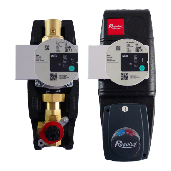
- Page 1 Installation and Operation Manual CSE MIX W6 1F PUMP STATION with mixing valve CSE MIX W6 1F...
- Page 2 1. Introduction CSE MIX W6 1F pump station is designed to be installed in heating circuits where it provides heating water mixing and circulation through the circuit. Its typical application is in mixed heating circuits in buildings where it provides circulation and mixing of heating water to a desired temperature, or for solid-fuel boiler circuits where it provides circulation and mixing to a min.
- Page 3 3. Pump Station Connection The diagram shows a typical connection of a solid fuel boiler, thermal store and heating circuit. If there is also the indicated hot water circuit, install the CSE OTS ZV pump station (not included in the supply). HW STORAGE TANK THERMAL STORE...
- Page 4 4. Mixing Valve Actuator Technical data Torque 5 Nm Angle of rotation 90° Shift time 120 s Control 3-point Auxiliary switch none Power supply 230 V AC Max. power input 2.5 VA IP rating IP42 Protection class II by EN 60730-1 Cable (cross section area - length) 3 x 0.5 mm²...
-
Page 5: General Information
5. PARA 25/6 SC 130 mm Pump 5.1. General Information The high efficiency circulation pumps of the PARA SC series are used exclusively for the circulation of liquids in hot water heating systems. Operating the pump in other systems or in systems lacking water, containing air or in unpressurized systems can lead to its rapid destruction. -
Page 6: Pump Wiring
5.4. Pump Wiring The pump must be wired / disconnected by a qualified person in compliance with EN 50110-1! Plug the power cable (2) into the connector on the pump so that the connector lock (1) is in the correct position, see Fig. POWER SUPPLY (1 ~ 230V, 50 Hz) brown - L blue - N... - Page 7 Press and hold the operating button for the specified time to activate:: - Pump venting function - hold the control button for 3 seconds. - Manual restart - hold the operating button for 5 seconds. - Locking / Unlocking the operating button - hold the button for 8 seconds. - Factory setting - hold the control button for at least 4 seconds and switch off the pump by disco- nnecting it from the mains.
-
Page 8: Manual Restart
PUMP VENTING If air is present in the pump: Activate the pump venting function by pressing and holding the operating button for 3 sec. The upper and lower rows of LEDs will flash in 1sec interval, see Fig. Pump venting takes 10 minutes, after that the pump returns to current mode. -
Page 9: Factory Settings
OPERATING BUTTON LOCKING / UNLOCKING To lock the operating button, press it for 8 seconds. The selected setting then starts flashing and cannot be changed. To unlock, hold down the operating button again for 8 seconds and the LEDs will stop flashing. FACTORY SETTINGS To return to the factory settings, press and hold the operating button for at least 4 seconds (all LEDs flash for 1 second) and turn off the pump by unplugging. -
Page 10: Pump Operating Modes
PUMP OPERATING MODES Variable differential pressure Δp-v It is not recommended to use variable differential pressure for solid fuel boiler pumps! The Variable differential pressure operating mode is recommended in systems where it is advisable to reduce the discharge pressure of the pump in parallel with the decreasing required flow rate. - Page 11 Δp-c Constant differential pressure The Constant differential pressure (constant delivery head) operating mode is suitable for hydraulic circuits of heat sources (boilers, heat pumps, solar thermal systems etc.), hot water storage tanks, heaters, underfloor heating systems and large heating circuits where the previous mode Δp-v could cause insufficient heating through discharge reduction.
-
Page 12: Constant Speed
Constant speed Constant speed operating mode means that the pump does not adjust its speed in any way depending on the flow rate or discharge of the hydraulic circuit. The flow and discharge of the pump are thus entirely dependent on the speed setting set (I, II, III) and the hydraulic circuit settings. This mode is used when the more economical Δp-c mode is not suitable. -
Page 13: Technical Data
5.6. Technical Data Wilo PARA 25/6 SC 130 mm Pump Electric Data Power supply 230 V, 50 Hz Power input (min./max.) 3/43 W Current (min./max.) 0.04/0.44 A Max. speed 4300 rpm Speed control frequency converter Energy Efficiency Index ≤ 0.21 by EN 16 297/3 IP rating IPX4D Motor protection... -
Page 14: Troubleshooting
5.7. FAULTS, THEIR REASONS AND TROUBLESHOOTING The LED light signals a defect. The pump will switch off (depending on the defect type) and try to restart. state description and possible fault reasons LED indication green is lit 1 - pump is running in trouble-free operation 1 - rotor is blocked red is lit 2 - electric motor winding defect... -
Page 15: Installation Options
Installation options The pump station comes with a mixing valve in the left-hand position (see Fig. 1). If this installation position is convenient, there is no need to make any adjustments. If you remove the actuator during installation, do not turn the valve control manually and refit the actuator in the same position. When needed, the mixing valve can be rotated to the right-hand position (see Fig. -
Page 16: Actuator Adjustment
Actuator adjustment Having turned the valve to the right hand position, turn the D-shaft in such a manner that the valve member is between inlets 1 and 3, turn the red plastic wheel properly (see Fig. 4) and finally fit the plastic adapter (the arrow on the plastic adapter forms an angle of 45°... - Page 17 Prior to fitting the actuator on the plastic adapter, switch it to manual control, set the control knob to the middle of its control range (i.e. to the divide between red and blue on the label) and then fit the actuator onto the adapter already on the valve.
- Page 18 (boiler to the right from the pump station, see Fig. 8). Fig. 7 Fig. 8 v1.0-11/2020 ©2020 We reserve the right to errors, changes and improvements without prior notice. REGULUS spol. s r.o. E-mail: sales@regulus.eu Web: www.regulus.eu...
Need help?
Do you have a question about the CSE MIX W6 1F and is the answer not in the manual?
Questions and answers