
Related Manuals for Regulus CSE SOL W SRS1 T-E HDO


Summary of Contents for Regulus CSE SOL W SRS1 T-E HDO
- Page 1 Installation and Operation Manual CSE SOL W SRS1 T-E HDO SOLAR PUMP STATION, 2-20 l/min w. electronic control & flow rate measurement CSE SOL...
- Page 2 1. Introduction CSE SOL W SRS1 T-E HDO Solar Pump Station is fitted with a solar pump of the latest generation that permits smooth flow control through PWM signal and sends information on the actual flow rate to the controller that shows the value on its display. The complicated setting of the right flow rate is not needed, the Pump Station keeps adjusting it automatically, depending on the actual solar radiation.
- Page 3 3. Data for the Pump Station and Accessories CSE SOL W SRS1 TE HDO Pump Station Data Max. fluid working temperature Max. working pressure Min. system pressure 1.3 bar with the pump stopped Flow rate measurement range* 2 - 20 l/min Electric heating element resistive load max.
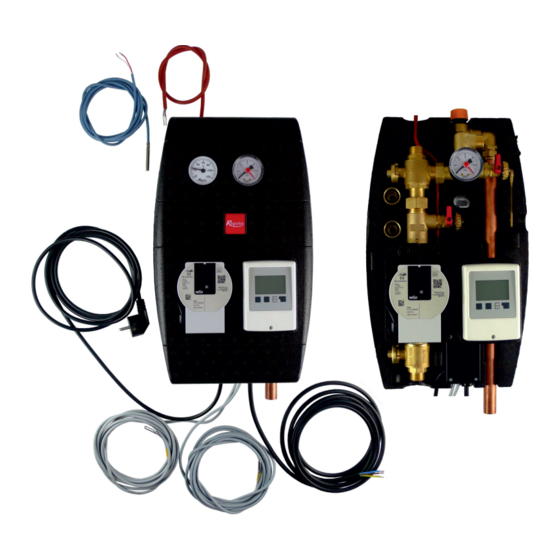
- Page 4 Pump Station Pressure Drop Graph 4. Pump Station Components BALL VALVE SOLAR CIRCULATION PUMP NON-RETURN VALVE FILL/DRAIN HOSE SOCKET BALL VALVE WITH T-BRANCHE FOR SAFETY ASSY THERMOMETER (IN INSULATION UPPER PART) PRESSURE GAUGE EXPANSION VESSEL CONNECTION POINT, ¾” M 6 BAR SAFETY VALVE FILLING BALL VALVE 10 - SPANNER FOR BALL VALVES...
-
Page 5: Non-Return Valve
4.1 Non-return Valve The non-return valve prevents the tank from being cooled down by gravity circulation during periods of no sunshine. It is located between the ball valves so it can be removed and cleaned without the need to drain solar fluid from the entire solar circuit. When the red mark is on the left-hand side, the non-return valve is set to normal operation position. -
Page 6: Installation Options
6. Installation Options The solar pump station is designed to be installed on a wall or on a tank. There are two installation openings in the insulation rear part. The lower one is accessible only after the electronic controller is removed from the insulation rear part (see fig.). - Page 7 7.1 Recommended Hydraulic Variant NOTE: The number of the variant corresponds to the numbering of preset variants in the SRS1 T controller. There are also variants 2 to 6 present in the controller but those are not recommended for this variant of a solar pump station.
- Page 8 8.2 Performance Curves for Para ST 25/7-50/iPWM2 Pump 12 15 18 21 24 27 30 33 36 39 42 45 48 51 Q [l/min] 4700 4200 3700 3200 2700 2200 1700 1200 12 15 18 21 24 27 30 33 36 39 42 45 48 51 Q [l/min] NOTE: 1) value of PWM signal in % 2) speed in rpm...
- Page 9 9. Filling a Solar Thermal System For filling a solar thermal system, the ball valve above the pump must be closed and the ball valve below the pump open. The open/closed position is indicated by a groove on the ball valve. If the groove is pointing horizontally, the ball valve is closed;...
- Page 10 ©2019 We reserve the right to errors, changes and improvements without prior notice. v1.3_10/2019 E-mail: sales@regulus.eu Web: www.regulus.eu...
Need help?
Do you have a question about the CSE SOL W SRS1 T-E HDO and is the answer not in the manual?
Questions and answers