Regulus CSE2 MIX-BP F G 1F Installation And Operation Manual
Pump station
Hide thumbs
Also See for CSE2 MIX-BP F G 1F:
- Installation and operation manual (20 pages) ,
- Installation and operation manual (20 pages) ,
- Installation and operation manual (14 pages)

Subscribe to Our Youtube Channel
Related Manuals for Regulus CSE2 MIX-BP F G 1F


Summary of Contents for Regulus CSE2 MIX-BP F G 1F
- Page 1 Installation and Operation Manual CSE2 MIX-BP F G 1F PUMP STATION CSE2 MIX-BP F G 1F...
-
Page 2: Table Of Contents
UPM3 FLEX AS 25-75 130 PUMP ..........3.2. LK 840 MIXING VALVE ..............3.3. CHECK VALVE ................3.4. FILTER WITH MAGNET ..............3.5. BALL VALVES ................PUMP STATION INSTALLATION ............. TEMPERATURE SENSOR INSTALLATION ..........OPTIONAL ACCESSORIES ..............Regulus CSE2 MIX-BP F G 1F - www.regulus.eu │... -
Page 3: Introduction
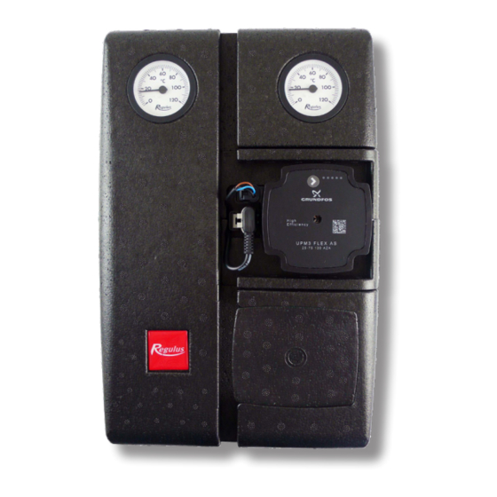
INTRODUCTION CSE2 MIX-BP F G 1F twin-line pump station is designed for mixed heating circuits. It provides flow through the heating system, mixes to the outlet temperature. Since the mixing valve is not fitted with an actuator, any actuator may be used that will meet the needs of the particular system and control. -
Page 4: Pump Station Components
6 – Lever for ball valves 7 – Ball valve w. sheath for temperature sensor (heating circuit outlet) 8 – Ball valve w. sheath for temperature sensor (heating circuit inlet) 9 – LK 840 mixing valve Regulus CSE2 MIX-BP F G 1F - www.regulus.eu │... -
Page 5: Upm3 Flex As 25-75 130 Pump
PWM GND (blue) PWM out (black) PWM in (brown) socket for power supply (A) power supply (A) and and signal transmission (B) signal (B) connectors Pump Performance Curves Curve (upper graph) (lower graph) Regulus CSE2 MIX-BP F G 1F - www.regulus.eu │... - Page 6 7,5 m ERROR DISPLAY The fault is indicated on the pump display by LEDS, as shown in the following figure. seized pump too low power supply voltage electric fault Regulus CSE2 MIX-BP F G 1F - www.regulus.eu │...
-
Page 7: Lk 840 Mixing Valve
Gasket EPDM Mixing Valve Pressure Drop Diagram 3.3. CHECK VALVE The check valve downstream of the filter prevents natural circulation in the heating circuit. Check Valve Pressure Drop Diagram V [m Regulus CSE2 MIX-BP F G 1F - www.regulus.eu │... -
Page 8: Filter With Magnet
Dirt trapped on the magnet must be wiped off and then reassembled by inserting the strainer, screwing in and tightening the cap. Filter w. Magnet Pressure Drop Diagram Regulus CSE2 MIX-BP F G 1F - www.regulus.eu │... -
Page 9: Ball Valves
As a result, unintentional closure of the system by an unauthorized person is not possible. OPEN CLOSED groove in the flow direction groove perpendicular to the flow direction Regulus CSE2 MIX-BP F G 1F - www.regulus.eu │... -
Page 10: Pump Station Installation
The package includes a mounting kit that is used to fix the pump station to the intended place. The mounting kit includes: Screw 5x50, round head 2 pcs 6.4 stainless steel washer, DIN 9021/A2 2 pcs Wall plug 8mm TX 2 pcs Regulus CSE2 MIX-BP F G 1F - www.regulus.eu │... -
Page 11: Temperature Sensor Installation
Temperature sensor placement Securing the temperature sensor with the screw Running the sensor cable through the recess in the insulation Regulus CSE2 MIX-BP F G 1F - www.regulus.eu │... -
Page 12: Optional Accessories
Code 17928 – G 1“ Fu x G 5/4“ F manifold connection fittings Code 17920 Code 17928 v1.0-06/2020 ©2020 We reserve the right to errors, changes and improvements without prior notice. REGULUS spol. s r.o. E-mail: sales@regulus.eu Web: www.regulus.eu...
Need help?
Do you have a question about the CSE2 MIX-BP F G 1F and is the answer not in the manual?
Questions and answers