Regulus CSE2 SOL G P Installation And Operation Manual
Solar pump station
Hide thumbs
Also See for CSE2 SOL G P:
- Installation and operation manual (10 pages) ,
- Installation and operation manual (12 pages)

Related Manuals for Regulus CSE2 SOL G P


Summary of Contents for Regulus CSE2 SOL G P
- Page 1 Installation and Operation Manual CSE2 SOL G P SOLAR PUMP STATION CSE2 SOL G P...
- Page 2 1. Introduction Thanks to its design, CSE2 SOL G P solar pump station enables a simple and quick conenction into a solar circuit. It is fitted with a high-efficiency solar pump of the latest generation that permits continous flow control.
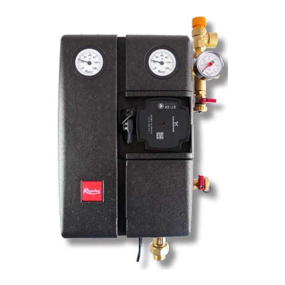
- Page 3 3.1 Pressure drop diagram G 3/4“ M connection - code 19983 G 3/4“ M connection - code 19990 4. Pump Station Components 1 - FLOWRATE INDICATOR W. BALL VALVE 2 - CIRCULATION PUMP 3 - CHECK VALVE 4 - BALL VALVE ON THE INCOMING PIPE FROM SOLAR COLLECTORS 5 - BALL VALVE W.
-
Page 4: Check Valve
4.1 Check valve The check valve prevents the tank from cooling down due to gravity circulation when the sun is not shining. It is located below the ball valves and can therefore be removed and cleaned without having to drain the solar fluid from the entire circuit. 4.2 Ball valves Ball valves are used to separate the pump station from the solar circuit. -
Page 5: Installation Options
6. Installation Options The solar pump station is designed to be mounted on a wall or a tank. In the rear section of the in- sulation there are three mounting holes. The two upper holes are intended for installation on a wall using the mounting kit included in supply. -
Page 6: Pump Control
8. UPM3 HYBRID 25-70 Pump Pump control The circulation pump can be controlled: • internally without PWM signal by selecting a constant pressure or constant speed mode and a desired pump curve. • externally by PWM C control signal (profile for solar systems) WARNING –... - Page 7 Description of Pump Frofiles a) INTERNAL CONTROL - Proportional pressure • Head (pressure): reduced with growing system pressure drop and increased with sinking system pressure drop. • Pump operating point: moves up or down on the selected proportional pressure curve depending on the current system pressure drop.
-
Page 8: Settings Display
Settings Display DISPLAY - MARKING OF LEDs For clarity, the marking of the LEDs is further omitted. DISPLAY CONTROL MODE green LED NOT FLASHING INTERNAL Proportional pressure AUTO - not used for ADAPT solar thermal systems Constant pressure AUTO - not used for solar ADAPT thermal systems Proportional pressure - not used... -
Page 9: Setting Selection
FLASHING FREQUENCY OF CONTROL RECEIVING PWM SIGNAL GREEN LEDS Not flashing Internal 1 flash per second External 12 flashes per second External WARNING: LEDs may be turned by 90° or 180°, or mirrored, depending on the specific pump type. When switched on, the pump runs at factory settings or the last setting. The display shows the current pump performance. - Page 10 ©2023 We reserve the right to errors, changes and improvements without prior notice. REGULUS spol. s r.o. E-mail: sales@regulus.eu Web: www.regulus.eu...
Need help?
Do you have a question about the CSE2 SOL G P and is the answer not in the manual?
Questions and answers