
Related Manuals for Regulus CSE SOL G P


Summary of Contents for Regulus CSE SOL G P
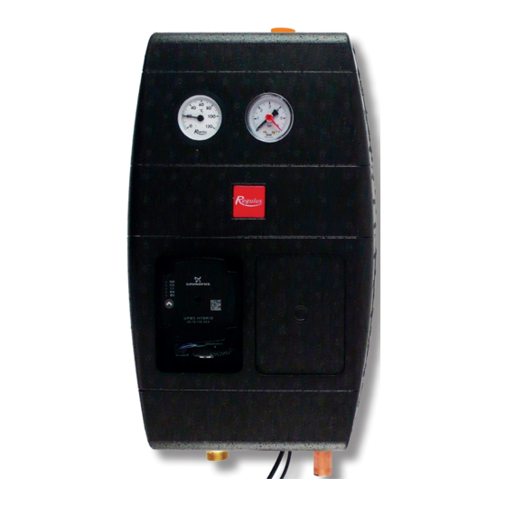
- Page 1 Installation and Operation Manual CSE SOL G P SOLAR PUMP STATION CSE SOL G P...
- Page 2 1. Introduction CSE SOL G P Solar pump station allows a simple and fast connection to a solar thermal circuit thanks to its design. It is equipped with a high-efficiency solar pump of the latest generation that permits continuous flow control.
- Page 3 3.1 Pump Station Pressure Drop Graph Flowmeter 2-12 l/min Flowmeter 8-28 l/min 4. Pump Station Components 1 – FLOW RATE INDICATOR W. BALL VALVE 2 – CIRCULATION PUMP 3 – CHECK VALVE 4 – FILL/DRAIN HOSE SOCKET 5 – BALL VALVE WITH T-BRANCHE FOR SAFETY GROUP 6 –...
-
Page 4: Check Valve
4.1 Check Valve The check valve prevents the tank from being cooled down by gravity circulation during periods of no sunshine. It is located between the ball valves so it can be removed and cleaned without the need to drain solar fluid from the entire solar circuit. When the mark is on the left-hand side, the check valve is set to normal operation position. -
Page 5: Installation Options
6. Installation Options The solar pump station is designed to be mounted on a wall or a tank. In the rear section of the insu- lation there are two mounting holes. The lower hole is accessible only when the electronic controller and wiring box are removed from the insulation rear section (see the fig. -
Page 6: Pump Control
8. UPM3 HYBRID 25-70 Pump Pump Control The circulation pump can be controlled: • internally without a PWM signal by selecting a suitable mode and pump performance curve • by an external PWM C control signal (profile for use in solar thermal systems) WARNING –... - Page 7 Description of Pump Frofiles a) INTERNAL CONTROL - Proportional pressure • Head (pressure): reduced with growing system pressure drop and increased with sinking system pressure drop. • Pump operating point: moves up or down on the selected proportional pressure curve depending on the current system pressure drop.
-
Page 8: Settings Display
Settings Display DISPLAY - LED MARKING The LED marking is further omitted for better clarity. DISPLAY CONTROL MODE green LED FLASHING INTERNAL Proportional pressure AUTO ADAPT Constant pressure AUTO ADAPT Proportional pressure Constant pressure Constant speed DISPLAY CONTROL MODE green LED NOT FLASHING EXTERNAL PWM C WARNING... -
Page 9: Setting Selection
GREEN LEDS FLASHING CONTROL PWM SIGNAL RECEPTION FREQUENCY Not flashing Internal 1 flash per second External 12 flashes per second External WARNING: LEDs may be turned by 90° or 180°, or mirrored, depending on the specific pump type. When switched on, the pump runs at factory settings or the last setting. The display shows the current pump performance. - Page 10 Prior to commissioning the system, both the ball valves must be open! CLOSED OPEN v1.0-11/2021 ©2021 We reserve the right to errors, changes and improvements without prior notice. REGULUS spol. s r.o. E-mail: sales@regulus.eu Web: www.regulus.eu...
Need help?
Do you have a question about the CSE SOL G P and is the answer not in the manual?
Questions and answers