Regulus CSE2 SOL W P Installation And Operation Manual
Hide thumbs
Also See for CSE2 SOL W P:
- Installation and operation manual (10 pages) ,
- Installation and operation manual (12 pages)

Related Manuals for Regulus CSE2 SOL W P


Summary of Contents for Regulus CSE2 SOL W P
- Page 1 Installation and Operation Manual CSE2 SOL W P SOLAR PUMP STATION CSE2 SOL W P...
- Page 2 1. Introduction Thanks to its design, CSE2 SOL W P solar pump station enables a simple and quick conenction into a solar circuit. It is fitted with a high-efficiency solar pump of the latest generation that permits continous flow control.
-
Page 3: Pressure Drop Diagram
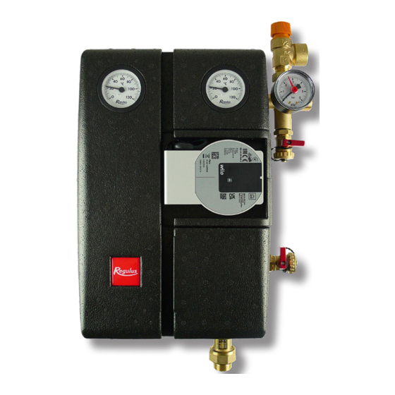
3.1 Pressure drop diagram G 3/4“ M connection - code 19998 G 3/4“ M connection - code 19985 4. Pump Station Components 1 - FLOWRATE INDICATOR W. BALL VALVE 2 - CIRCULATION PUMP 3 - CHECK VALVE 4 - BALL VALVE ON THE INCOMING PIPE FROM SOLAR COLLECTORS 5 - BALL VALVE W. -
Page 4: Check Valve
4.1 Check valve The check valve prevents the tank from cooling down due to gravity circulation when the sun is not shining. It is located below the ball valves and can therefore be removed and cleaned without having to drain the solar fluid from the entire circuit. 4.2 Ball valves Ball valves are used to separate the pump station from the solar circuit. -
Page 5: Installation Options
6. Installation Options The solar pump station is designed to be mounted on a wall or a tank. In the rear section of the in- sulation there are three mounting holes. The two upper holes are intended for installation on a wall using the mounting kit included in supply. -
Page 6: Performance Curves
8. Wilo-Para iPWM2 Pump The Wilo Para 25/7 iPWM2 is a wet running circulation pump. The pump speed is controlled by the PWM signal. When the PWM signal is disconnected, the pump stops running (a pump for solar thermal systems). The operating status and possible faults of the pump are indicated by LEDs directly on the pump. -
Page 7: Technical Data
8.2 Technical Data Wilo PARA 25/7 iPWM2 Electric Data Power supply 1 ~ 230 V, 50 Hz Power input (min./max.) 1.8 / 50 W Current (min./max.) 0.02 / 0,43 A Max. speed 4700 rpm Energy Efficiency Index ≤ 0.20 by EN 16 297/3 IP rating IPX4D Motor protection... - Page 8 8.4 Wilo PARA 25/7 iPWM2 Pump Wiring The pump must be wired / disconnected by a qualified person in compliance with EN 50110-1! 1.POWER SUPPLY (230 V, 50 Hz) 2.CONTROL (PWM) L (brown) PWM in (brown) N (blue) PWM GND (blue) PE (yellow-green) iPWM out (black) 9.
- Page 9 10. Solar System Air Venting • During operation of the filling pump, close the lower drain valve and increase the pressure to about 5 bar; • close the upper filling valve and turn off the filling pump, open the ball valve above the pump, do not disconnect the filling pump hoses! •...
- Page 10 ©2023 We reserve the right to errors, changes and improvements without prior notice. REGULUS spol. s r.o. E-mail: sales@regulus.eu Web: www.regulus.eu...
Need help?
Do you have a question about the CSE2 SOL W P and is the answer not in the manual?
Questions and answers