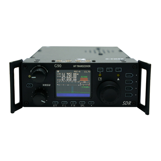
XIEGU G90 Operation Manual
Hf transceiver
Hide thumbs
Also See for G90:
- Operation manual (56 pages) ,
- Maintenance manual (48 pages) ,
- Operating instructions manual (38 pages)
Table of Contents
Advertisement
Quick Links
Advertisement
Table of Contents

Related Manuals for XIEGU G90


Summary of Contents for XIEGU G90
- Page 1 XIEGU HF Transceiver Opera�on manual Version 4.2.1 January 2022...
- Page 2 Ultra-Miniature 24 Bit SDR...
- Page 3 Customer Support team, we strive to fulfill our promise to be�er meet your needs every day. In order to protect your rights please read the terms on XIEGU Warranty Card carefully and know the Warranty Policy.
- Page 4 Warnings Please read this manual fully before opera�on so as to get a good understanding of the G90’s capabili�es and func�ons. When using an external mains power supply or ba�ery, carefully check the polarity of the power cord and do not reverse the polarity.
- Page 5 Please read this manual carefully for a be�er experience and a full understanding of the opera�on of the G90/S. The G90S is the version sold in the People's Republic of China, the G90 is the version available in other countries. This operation manual is applicable to both models.
-
Page 6: Table Of Contents
VISIT RADIODDITY.COM FOR DOWNLOADS AND HELP Index ................Specifica�ons ..............General Parameters ............Transmi�er Parameters ............... Receiver Parameters ........Accessories & Op�onal Components ..............Interface Defini�on ..........Machine Interface – Front Panel ..........Machine Interface – Rear Panel ..........Machine Interface – Head Unit ............ - Page 7 VISIT RADIODDITY.COM FOR DOWNLOADS AND HELP ........... Mul�-Func�on Adjustment Knob ........Using the SPL and VFOA/B Func�on ..........Automa�c Gain Control (AGC) ................PRE-AMP/ATT ......Pulse Interface Suppressor – Noise Blanker ............Voice Compression CMP ........CW (Morse Code) Communica�on ...............
- Page 8 .............. Data Communica�on ................Receiving ................Transmi�ng ............Cable Connec�on Steps Connec�ng the XPA125B Amplifier to the G90/S (Op�onal) ................System Menu ..........Menu Item 1: Handle up/down ............Menu Item 2: Handle F1 ............Menu Item 3: Handle F2 ..............
-
Page 9: Specifica�Ons
VISIT RADIODDITY.COM FOR DOWNLOADS AND HELP Specifica�ons General Parameters 0.5MHz~30MHz 1.8~2.0MHz (*1) 3.5~4.0MHz (*1) 5.331-5.405MHz (*1) 7.0~7.3MHz (*1) 10.1~10.15MHz Frequency range 14.0~14.35MHz 18.068-18.168MHz 21.0–21.450MHz 24.89-24.99MHz 28.0-29.7MHz Opera�ng modes USB/LSB/CW/CWR/AM/FM* Minimum step 10Hz Antenna impedance 50Ω Working temperature 0°C ~ +50°C ±1.5ppm in the 10~60min a�er startup Frequency stability @25°C: 1ppm/hour... -
Page 10: Transmi�Er Parameters
VISIT RADIODDITY.COM FOR DOWNLOADS AND HELP Transmi�er Parameters 20W(SSB/CW/FM) RF output power 5W (AM) @13.8VDC Spurious suppression ≥50dB Carrier suppression ≥40dB Microphone impedance 200~10k (600Ω in general) Receiver Parameters Circuit type Zero-IF (ZIF) direct conversion SDR Neighbor channel suppression ≥60dB Sideband suppression ≥60dB SSB/CW... -
Page 11: Accessories & Op�Onal Components
CE-19: host ACC socket adapter (can be used as PC interface to transmit audio signal or to control an XPA125B amplifier) XPA125B: 100W power amplifier, including an automa�c antenna tuner. GSOC: external, large screen, controller. G90-H1: Stand with fan G90-H2: Til�ng front support legs PAX-100: Radioddity HF amplifier. -
Page 12: Interface Defini�On
VISIT RADIODDITY.COM FOR DOWNLOADS AND HELP Interface Defini�on Defini�on of microphone interface Wiring diagram of COMM plug MICE MSVSW MDATA Wiring diagram of earphone plug BAND signal AF_OUT AF_IN signal 8V DC Left and right connections carry Rear ACC socket monaural audio Wiring of CW keys NOTE:... -
Page 13: Machine Interface - Front Panel
VISIT RADIODDITY.COM FOR DOWNLOADS AND HELP Machine Interface – Front Panel 1 Volume knob Turn the knob to increase or decrease the volume. A momentary press alternates between headphone/speaker output. 2 Power supply /transceiver indicator light Standby /receive state: yellow-green; Red indicates the radio is transmi�ng. - Page 14 VISIT RADIODDITY.COM FOR DOWNLOADS AND HELP 5-6 MODE switching Pressing these bu�ons will cycle through all the modes. 7-8 BAND switching Pressing these bu�ons will switch up or down through the Amateur bands or the Amateur and SW Broadcast bands (Transmission is only allowed in the HAM bands).
-
Page 15: Machine Interface - Rear Panel
VISIT RADIODDITY.COM FOR DOWNLOADS AND HELP Machine Interface – Rear Panel 13 Antenna interface SQ-239 type - impedance 50Ω. 14 KEY interface A 3.5mm stereo jack used to connect manual/paddle CW keys. (See Page 04 for the wiring details) 15 COMM interface Only used for upda�ng the radio body’s firmware at present. -
Page 16: Machine Interface - Head Unit
NOTE (point 22): 1. Insert the supplied 3.5mm to USB cable into this port for data transfer or CAT control mode communica�ons. 2. Do not insert the cable into this port before you start the G90/S up. -
Page 17: Hand Microphone Bu�Ons
VISIT RADIODDITY.COM FOR DOWNLOADS AND HELP Hand Microphone Bu�ons Mic element Func�onal indicator light LOCK bu�on Lights whenever a key is pressed Lock bu�on on the microphone. PTT bu�on Func�on bu�ons Press to transmit F1/F2 bu�ons (user-defined in Up/down the system menu) Frequency increase/ decrease bu�on –... -
Page 18: Power Source Connec�On
10.5-16.5VDC and have capacity to supply up to 10 amps. Typical current requirements on transmit are generally less than 8A. Use the provided cable to connect the G90/S to your DC supply. The G90/S transmi�er is designed in such a way that dropping supply voltage from a weak ba�ery has li�le effect on the transmi�er output power. -
Page 19: Func�Ons Of Bu�Ons
VISIT RADIODDITY.COM FOR DOWNLOADS AND HELP Func�ons of Bu�ons First func�on Second func�on Bu�on Long press (momentary press, cycle) (FUNC+) PRE - ATT - Normal. cycles PRE/ATT through these states. Digital filter F-L, low-pass Reset filter CMP/F-L Turn on voice compression cut-off... - Page 20 VISIT RADIODDITY.COM FOR DOWNLOADS AND HELP First func�on Second func�on Bu�on Long press (momentary press, cycle) (FUNC+) Insert/non- insert selec�on Hang �me QSK Time se�ng Se�ng of the automa�c key Ra�o dot-and-dash interval ra�o Spectrum SCALE reference level se�ng LOCK Lock / Screen brightness Lock bu�on Mean value...
-
Page 21: Screen Display Icons
VISIT RADIODDITY.COM FOR DOWNLOADS AND HELP Press the [FUNC] bu�on again to exit the secondary func�on. At this �me, the F indicator LED will go off. Pressing the [FUNC] bu�on for 1-2 seconds will take you into the System Menu (see later in this manual for details of parameters that can be set). In any func�on (including the secondary FUNC se�ng) a short press of the main knob will save the se�ng. - Page 22 VISIT RADIODDITY.COM FOR DOWNLOADS AND HELP CMP voice compression is ac�ve. squelch is ON. voice triggered TX control func�on is ON. AGC control is set to Slow (alterna�vely AGC-F, AGC-AUTO, AGC se�ngs may be indicated) supply voltage display. Current opera�ng mode in use is USB. (LSB, CW, CW-R and AM modes are alterna�ve values) As the split mode symbol is indicated between VFO-A and VFO-B, VFO-A is the current receive frequency and VFO-B is the transmi�ng frequency.
-
Page 23: Opera�On
VISIT RADIODDITY.COM FOR DOWNLOADS AND HELP Opera�on In order to familiarize yourself with the func�ons and capabili�es of the G90/S portable transceiver, please read the opera�on guide fully to understand the powerful func�ons of the G90/S. Transceiver start and shutdown 1. -
Page 24: Selec�On Of Working Frequency Range
Opera�on above the maximum voltage given in the specifica�ons will seriously damage the radio! The displayed voltage may vary ±0.3V from the actual value. The G90/S is uniquely designed such that lower voltages do not result in significantly reduced TX power or RX performance. Selec�on of Working Frequency Range The G90/S receives 0.5~30MHz but is set to only transmit on the amateur... -
Page 25: Opera�Ng Mode Selec�On
VISIT RADIODDITY.COM FOR DOWNLOADS AND HELP Frequency ranges for other bands can be dealer pre-set prior to sale in accordance to the regula�ons of the country (or region) of sale. VFO-A and VFO-B are two independent VFOs that can be set to different opera�ng bands. -
Page 26: Call Sign Editor
4. When the radio is re-started, your callsign will be displayed on the screen. Se�ng Opera�onal Frequency There are three methods to set the frequency of G90/S. You may use the large main knob, the mul�-func�on knob or the keypad bu�ons on the hand microphone. - Page 27 VISIT RADIODDITY.COM FOR DOWNLOADS AND HELP 2. Set frequency by using the mul�-func�on hand microphone Press the white [F-INP ENT] bu�on on the hand microphone. The G90/S will now be in frequency se�ng mode. The cursor will be blinking in the first column on the le�...
-
Page 28: Adjustment Of Rf Gain And Mu�Ng Level
VISIT RADIODDITY.COM FOR DOWNLOADS AND HELP Adjustment of RF Gain and Mu�ng Level Proper RF gain adjustment can improve the quality of a received signal. In general, reducing the RF gain level on the low bands (40/60/80/160m) which have strong interference can significantly improve receive quality. In general, with SDR rigs, operating at full RF gain is detrimental to receive signal quality. -
Page 29: Mul�-Func�On Adjustment Knob
Recep�on and Transmission Opera�ons Using the SPL and VFOA/B. The G90/S transceiver has two built-in, independent, VFOs which can be set to different frequencies and different modes. Using the SPL (split) func�on, you can transmit and receive on different frequencies. -
Page 30: Automa�C Gain Control (Agc)
VISIT RADIODDITY.COM FOR DOWNLOADS AND HELP VFO Opera�on VFO se�ng: 1. Momentarily press the [A/B / A>B] bu�on to switch between VFO-A and VFO-B; 2. Set the required VFO frequency and mode when on one VFO (A or B). Split Frequency Opera�on Split Opera�on (SPL) 1. -
Page 31: Pre-Amp/Att
VISIT RADIODDITY.COM FOR DOWNLOADS AND HELP NOTE: You should experiment with the AGC Off mode only if the received signal is not changing in strength due to fading (QSB). You must manually control the RF gain level so that you do not have distor�on from the incoming signal overloading the receiver. -
Page 32: Voice Compression Cmp
VISIT RADIODDITY.COM FOR DOWNLOADS AND HELP 2. Repeated momentary presses of the [NB] bu�on will select the different NB func�on se�ng op�ons. Rotate the main tuning knob to set these values. The NB func�on menu includes the following op�ons: NBSW: NB opera�on switch ON/OFF. Default is OFF NB Level: se�ng of NB suppression level. -
Page 33: Prac�Ce Mode
VISIT RADIODDITY.COM FOR DOWNLOADS AND HELP Prac�ce Mode You can use the G90/S as a CW code trainer using the following method: Disable the QSK func�on for the [KEY] func�on. Only the CW sidetone of the transceiver will be heard when using the CW key. Signals will not be transmi�ed. -
Page 34: Ssb Communica�On
VISIT RADIODDITY.COM FOR DOWNLOADS AND HELP Indicator A Keys To enter the second func�on of the [KEY] bu�on press [FUNC] bu�on and then [KEY] to select and set the following op�ons. Once adjusted using the main tuning knob, press the KEY bu�on again to exits the se�ngs process. Options: CW Volume: sidetone volume se�ng T800Hz: sidetone tone frequency se�ng... -
Page 35: Voice-Controlled Transmit - Vox
VISIT RADIODDITY.COM FOR DOWNLOADS AND HELP 2) SWR THR: set the standing-wave-ra�o protec�on threshold (default is 3:1). If the radio sees an SWR over this value it will reduce power to protect itself. 4. A�er you have set the parameters above you are ready for SSB communica�ons. -
Page 36: Se�Ng Line Level Input Into Acc Connector
100% duty cycle periods of some digital modes. Automa�c Antenna Tuner The G90/S has an efficient ATU to help you quickly match many kinds of antennas effec�vely. 1. Press the [TUNE] bu�on in momentarily to bring the built-in antenna tuner into circuit. -
Page 37: Standing-Wave Scanner Swr
If this happens try to locate the antenna further away. Standing-Wave Scanner SWR The G90/S has an antenna SWR scanning func�on. It can scan the standing-wave values of the connected antenna to help you adjust the antenna. A long press of the [POW] bu�on enables the standing-wave scanning func�on. -
Page 38: Fine Tuning Of Received Frequency (Rit)
When RIT is no longer required, reset the RIT value to 0. Line Input and Output The G90/S has an external line input interface. When the G90/S is used for data communica�on in conjunc�on with a computer or an external modem, the correct signal input op�ons need to be selected. -
Page 39: Channel Memory Write (Mw) And Clear (Mc)
“Sound devices”. It is best to set the radio to a mid-level value and then adjust the PC’s levels to achieve correct opera�on. Fine tuning from that point can be done through the G90/S’s menu se�ngs. Channel Memory Write (MW) and Clear (MC) Basic opera�ons:... -
Page 40: Transmi�Er Power Se�Ng
It is always good to start with reduced TX power if you are unsure of your antenna’s condi�on or are new to the opera�on of your G90/S. Once you know your SWR is low and grounding is good, the radio is designed to... -
Page 41: Digital (Dsp) Filters
VISIT RADIODDITY.COM FOR DOWNLOADS AND HELP Digital (DSP) Filters The G90/S has a built-in variable digital filter that can con�nuously adjust the bandwidth of the receiver’s input to improve recep�on of the desired signal. The G90/S has two filter adjustment modes: center frequency point mode and bandwidth mode. -
Page 42: Spectrum/ Waterfall Display
300-500 Hz is normally ideal. Spectrum/ Waterfall Display The G90/S radio can display the radio spectrum and waterfall diagrams of received signals and you can quickly observe whether there is a signal on the desired frequency of opera�on. You can also easily iden�fy a clear frequency to QSY (move freq.) to in case there is QRM (interference) occurring on the... -
Page 43: Data Communica�On
This se�ng is a ma�er of personal taste. It can improve usability of the spectrum display. Data Communica�on The G90/S supports all PC-generated amateur data communica�on modes and remote control via computer so�ware when a PC is linked to the radio. Only simple wiring is needed to enable amateur data communica�ons. -
Page 44: Cable Connec�On Steps
(ring) connec�on on the stereo plug is the TX audio in. Ground is the third connec�on. Set the G90/S to "Line input" mode (i.e. take the audio from the ACC socket rather than from the hand microphone.) Set the G90/S to the appropriate TX mode for the par�cular digital mode... - Page 45 VISIT RADIODDITY.COM FOR DOWNLOADS AND HELP At this point, the wiring is complete. Remember to keep the PC audio (speaker) level output low and watch your ALC level when going onto transmit. Raise the PC output level un�l you see the ALC just start to respond...and then stop.
-
Page 46: Connec�Ng The Xpa125B Amplifier To The G90/S (Op�Onal)
VISIT RADIODDITY.COM FOR DOWNLOADS AND HELP The wiring of the 3.5mm sockets are shown on the CE-19 board. The port labelled X5105 is also for the G90/S and accepts the 8-core cable from the ACC port of the radio. The audio cable is connected as follows: AF_OUT: to PC Audio input. -
Page 47: System Menu
VISIT RADIODDITY.COM FOR DOWNLOADS AND HELP The output power of the G90/S should be set to be ≤2.5W to protect the amplifier. The amplifier can give full output power with very li�le drive on the input socket. The 8-pin ACC wire is included with the CE-19 kit. The 6-pin ACC wire is included with the XPA125B. -
Page 48: Menu Item 1: Handle Up/Down
VISIT RADIODDITY.COM FOR DOWNLOADS AND HELP Use the main VFO tuning dial to change values. Menu Item 1: Handle up/down Func�on: Customize the func�on of [▲▼] bu�ons on the hand microphone. Op�onal value FREQCH+/- Frequency/channel+/- BAND+/- Band+/- VOLUM+/- Volume+/- Default: FREQCH+/- Menu Item 2: Handle F1 Func�on: Customize the func�on of [F1] bu�on on the hand microphone. -
Page 49: Menu Item 5: Aux In Volum
VISIT RADIODDITY.COM FOR DOWNLOADS AND HELP Menu Item 6: AUX OUT Volum Func�on: Set the level (volume) of ACC port output audio signal Adjustable range: 0~15 The large the value, the greater the volume Default: 15 Menu Item 7: RCLK Tune Func�on: Adjust the reference clock of the internal frequency synthesizer. -
Page 50: Factory Reset
Default parameters can meet most opera�ng needs. This is a good test to see if your radio is opera�ng normally. Computer Control Instruc�ons The G90/S uses a subset of the standard CiV CAT instruc�on set. You can remotely control the transceiver based on standard instruc�ons or configure control instruc�ons for other so�ware. - Page 51 VISIT RADIODDITY.COM FOR DOWNLOADS AND HELP Table 1 (part 2/3) Sub-CMD DATA Descrip�on 0x11 Get ATT Get AF level (Rx volume) return 0x01 values are in BCD code format 0x03 Get SQL level 0x09 Get CW sidetone frequency 0x0A Get Tx power 0x0C Get CW key speed Always return 255...
- Page 52 VISIT RADIODDITY.COM FOR DOWNLOADS AND HELP Table 1 (part 3/3) Sub-CMD DATA Descrip�on 0x00 AGC OFF AGC Fast 0x01 0x12 0x02 AGC middle 0x03 AGC slow NB OFF 0x00 0x16 0x22 NB ON 0x01 0x00 COMP OFF 0x44 0x01 COMP ON Dial encoder unlock 0x00 0x50...
-
Page 53: Wave Band Voltage Data
Xiegu regularly releases firmware updates for the G90/S. Please go to radioddity.com and follow the Support link. All informa�on for upda�ng your G90/S will be there. The USB cable for performing updates is included with the G90/S. Be sure to install the cable driver from the Radioddity website on your... - Page 54 2. When connected to GSOC, all sounds in CW mode will be played by the G90/S speakers. If the modem func�on is turned on, the sounds will be played via the GSOC. Compatible with GD MCU and ST MCU...
- Page 55 VISIT RADIODDITY.COM FOR DOWNLOADS AND HELP firmware version after V1.77 (including 1.77V), if it is updated to the firmware version before 1.77V, it may not work normally. What’s new in 1.7.5 1. New system menu opera�on logic, change system menu item by pressing BAND Up/Down key (Equivalent to press PREV/NEXT) 2.
- Page 56 VISIT RADIODDITY.COM FOR DOWNLOADS AND HELP 7. Added microphone filter of SSB mode to a�enuate par�al low frequency component of microphone signal and improve emission efficiency 8. Changed the color of lines in frequency spectrum picture into green and fill color into semitransparent green 9.
- Page 57 Adjust it to your personal preference. NOTE: The G90/S is dealer modifiable for use on the US MARS required transmit frequency ranges. Your antenna will have a great impact on the quality of your communica�ons.
- Page 58 XIEGU...
Need help?
Do you have a question about the G90 and is the answer not in the manual?
Questions and answers
Здравствуйте. Нужно ли отключать тюнер джи 90 при передаче, после того как он настроил антенну?
No, the XIEGU G90 tuner does not need to be turned off during transmission after tuning the antenna.
This answer is automatically generated