XIEGU G90 Operation Manual
Portable hf sdr transceiver, ultra-miniature 24 bit sdr
Hide thumbs
Also See for G90:
- Operation manual (58 pages) ,
- Maintenance manual (48 pages) ,
- Operating instructions manual (38 pages)

Related Manuals for XIEGU G90


Summary of Contents for XIEGU G90
- Page 1 Ultra-Miniature 24 Bit SDR Portable HF SDR Transceiver Operation manual V1.01.00 April 2019...
-
Page 2: Table Of Contents
Computer Control Instructions Rear Panel Band/Voltage Output for Ext. Amp Side Panels Specifications Connector Pin-Outs Packing Items List MIC Buttons G90 and XPA125B Connection Diagram External Power Connection 11-12 CE-19 Expansion Card Interface LCD Display Copyright Statement Power On/Off Bands Selection... -
Page 3: Basic Features
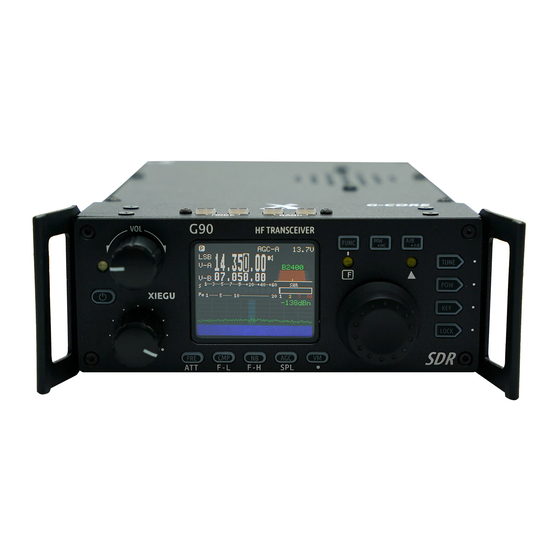
The G90 is a portable 20W HF SDR amateur radio transceiver with built-in auto antenna tuner. The display unit and the radio can be separated. It is a new member of the Xiegu product family and the first model of the new “G” series. -
Page 4: Panel Buttons
Side Panel 1 Volume knob Press and hold this knob to select Custom Functions. Turn to control the speaker volume. 5~6 Mode switching Short Press In: Switches to headphone output mode. TX/RX Mode switching 2 Power/ Receive or transmitting status pilot lamp. 7~8 BAND Switching –... - Page 5 Side Panel F Indicator light This LED will light yellow when you have CW tuned Function buttons: into the correct pitch. It will blink in sync with the incoming CW characters. 12. TUNE: Antenna Tuner on/off and set. 13. Po: Transmitter power output adjust 14.
- Page 6 Side Panel G90 Front Panel Connector Layout:...
- Page 7 The Firmware update files and TerraTerm program used to update the G90 are available on the Xiegu website. It may also be used for CAT control of the G90. Other uses for this port may be implemented in future firmware updates.
-
Page 8: Rear Panel
Rear Panel 19. Antenna interface 21. COMM interface SQ-239 type. Impedance 50Ω Firmware Expandable I/O connection. 20. KEY interface Currently used for main unit Firmware updates. The interface is a 3.5mm stereo jack for connection 22. I/Q Signal output to manual/automatic CW keys. The interface is a 3.5mm stereo jack for “I/Q”... -
Page 9: Connector Pin-Outs
Rear Panel 1、 MIC Interface 4、ACC Interface MICE DATA MSVSW AF_OUT MDATA AF_IN BAND 2、 COMM Connector 5、CW Key Wiring Diagram 3、 Headphone Interface... -
Page 10: Mic Buttons
MIC Buttons 1、LOCK Lock button 2、PTT Transmit control button 3、UP / DOWN Frequency "+" or "-" buttons 4、RX/TX indicator Hand Mic operation indicator 5、Numeric keypad Numeric keypad area 6、FIL Filter selection 7、MODE RX/TX operation mode 8、Function indicator 9、Function button F1/F2-configurable settings 10、MW Memory Storage operation 11、V/M... -
Page 11: External Power Connection
External Power Connection The G90 can use a 13.8V external DC power supply. The DC power supply must have a current load capacity of at least 10A. 13.8-14.3 VDC required for 20 watts output. The supplied power cord can be used to connect radio and your DC power. -
Page 12: External Power Connection
External Power Connection The power cord wraps around the ferrite core 2 turns. As close as possible to the plug. When using an external power supply, carefully check the polarity of the power cord and do not reverse the polarity. ... -
Page 13: Lcd Display
LCD Display Many of the G90’s buttons have dual functions. Main functions are accessed by a short press and alternate functions are accessed by a long-press of the control button. All the functions states and values are reported through the 1.8”... -
Page 14: Power On/Off
1 second. To turn OFF LCD screen (save batt power): Power button When the G90 is ON, quickly tap the main PWR button and the LCD screen will power off. The radio will remain ON. Hit any button on the radio to turn the LCD screen back ON. -
Page 15: Bands Selection
LCD Display Operating frequency band selection The G90's frequency range covers 0.5 to 30 MHz. Amateur frequencies within this range are divided into 10 bands. Band switching can be performed in a number of different ways. SW bands are included. -
Page 16: Operating Mode Selection
LCD Display VFO-A and VFO-B are two independent VFO’s that can be set independently. Operating mode select MODE ] Pressing the [ button increments through the available operating modes. : Mode left loop Mode right loop The FM mode can only be turned on when used with the GSOC controller. -
Page 17: Volume Adjustment
LCD Display VOLUME CONTROL Speaker mode: Rotate the volume knob left or right to adjust the level of received volume. Headphone mode: Press the volume knob inwards momentarily to enter headphone mode and mute the speaker. Rotate the volume knob left or right to adjust the level of the headphone volume. -
Page 18: Multi-Function Adjustment Knob
This is handy for use when you only connect the RX and TX audio lines to the Acc. This will Key the G90’s TX key the radio automatically using digital modes. (no CAT required) When using the AF IN port of the ACC interface for line input audio, set the appropriate input volume level in the system menu. -
Page 19: Adjusting Transmit Power
2、 Then use the multi-function knob to Knob set the output power in 1W increments. *When using the G90 transceiver for the first time without knowing for sure your antenna has a low SWR, minimize the set transmit power output. -
Page 20: Setting Operation Frequency
3. Set the frequency manually using the microphone: Press the [F-INP ENT] button on the microphone. The G90 enters the frequency setting state. The cursor will blink in the first position on the left side of the frequency display. -
Page 21: Automatic Antenna Tuner
LCD Display Automatic Antenna Tuner This G90 has a high-efficiency automatic antenna tuner that can help you quickly set up your antenna. Tuner A short press of the [TUNE] button will activate the built-in antenna tuner. The "TUNE" logo will be displayed at the top of the screen. -
Page 22: Function Buttons
LCD Display Function button The G90’s common functions are distributed on the various function keys. Some function keys have a second function. When the function is selected, turn the main knob to adjust the value. Operation of the second function: ... - Page 23 LCD Display Button function table Button Hold press Func1 (press,cycle) Func 2(FUNC+) PRE/ATT PRE--ATT--Normal CMP/F-L Turn on transmit voice compression Digital filter F-L low-end frequency selection Turn on Noise Blanker – on/off, Level, Width NB/F-H Digital filter F-H high-end frequency selection AGC/SPL AGC off、AGC-S、AGC-F、AGC-Auto Turn on split frequency transceiver operation mode...
-
Page 24: Vfo And Split (Spl) Operation
LCD Display Split frequency operation SPL and VFO A/B settings There are two independent VFOs inside the G90 VFO operation transceiver. We can set different frequencies and modes separately. With the SPL function, you can set up independent TX and RX frequencies. -
Page 25: Cw Transmission
LCD Display CW communication Operate with a straight key or paddles of common types. Key button Operation method: 1、 Insert the key body (three-wire) plug into the KEY interface; 2、 Press the [MODE] button to switch the mode to CW (or CWR); 3、... -
Page 26: Swr Scanner
LCD Display Standing wave ratio scanner The G90 has an antenna standing wave scanning/plotting function. It will scan and plot the antenna’s SWR over several frequency range widths settable by the user. Operation method : Press and hold the [POW] button to start the standing wave plotting function. -
Page 27: Digital Bandwidth Filter
LCD Display Digital filter The G90 has a built-in variable digital RX bandwidth filter. Bandwidth value Operation method: 1. Press the [FUNC] button to start the second function operation. 2. Press the [ CMP/F-L ] button to adjust the lower end of the filter and press the [ NB/F-H ] to adjust the upper end of the filter. -
Page 28: Line Input /Output Selection
LCD Display Line input / output The G90 has an external line input interface. Line Input Operations: Input the external audio signal to the corresponding pin of the ACC port (see the interface description section for pin definition). ... -
Page 29: Channel Memories
LCD Display Channel storage MW - Clearing a Memory Channel Channel storage: In the VFO mode, adjust the required frequency, mode and other parameters; Press the [ MW/MC ] button momentarily and the CH 00 (channel number) character will appear on the screen flashing. Rotate the main knob to select an empty channel. -
Page 30: Setting Boot Screen Callsign
LCD Display G90 boot screen call sign setting - CALL SIGN EDITOR The G90 can display your call sign on the boot-up screen. Operating method: 1. Press and hold the [VM] button to enter the text editor. 2. At the bottom of the screen is the character selection area. Rotate the main knob to select the desired character. Short press the main knob inwards to select the character. -
Page 31: System Menu
LCD Display System menu description Press and hold the [ FUNC ] button to enter the system menu. The various menu functions are defined as follows: Serial number Menu name Function Description Mic up/down Hand mic up/down button function setting Handle F1 Hand mic F1 button function setting Handle F2... -
Page 32: Pc Data Comm. Connections
3. Connect the audio output signal of the computer to the audio input port of the G90 (AF_IN pin of the ACC port). The #5 item of the system menu can adjust the volume of the input signal. (*see below) 4. -
Page 33: Computer Control Instructions
The G90 uses the standard CIV instruction set. You can use the standard commands of this instruction set to remotely control the transceiver. It can also be used to configure the control instructions of other software to control the G90. To get going rapidly, you can use the configuration file for another radio that uses the standard instruction set. -
Page 34: Specifications
General Specifications: Receiver Specifications: Circuit type: Mixer SDR 24 bit 48khz Frequency Range: receive:0.5MHz~30MHz Adjacent channel suppression: ≥60dB transmitting: 160M~10M Sideband suppression: ≥60dB ( ) Amateur radio band only Sensitivity: Transmitting modes: A1A(CW),A3E(AM),J3E(USB/LSB) Minimum Frequency step: 10Hz Antenna impedance: 50Ω SSB/CW/FM Range of operating temperature:... -
Page 35: Packing Items List
Accessories and options Packing List Item name Quantity 1pcs Multi-function handle 1pcs Data cable 1pcs Power cable 1pcs Remote head DB-9 cable 1 pcs Operation Manual 1pcs Warranty Card 1pcs Fixed stud 2pcs Hexagon screwdriver 1pcs Certificate 1pcs * Optional accessories Description Item name CE-19... -
Page 36: G90 And Xpa125B Connection Diagram
Connection diagram between G90 and XPA125B ACC口 TO XPA125 CE-19 XPA125B 6芯线 8芯线 8 Pin 6 Pin *note:The 8-wire ACC control line is provided in the CE19 kit. -
Page 37: Expansion Card Interface
CE-19 expansion adapter interface diagram PTT CON PTT signal / BAND signal output port. The PTT signal of this port is completely isolated from the radio. TO XPA125B XPA12B dedicated interface. AF CON Audio input/output port. The audio output from this port is direct demodulated output with no filtering applied. DATA CON Data output port in NFM mode. -
Page 38: Copyright Statement
All rights reserved 2018 Chongqing Xiegu Technology Co., Ltd. reserves all rights to this manual, and reproduction of any part of this manual is prohibited without permission. ------------------------------------------------------------------------------------------------ V1.1.00 1010160204-C...
Need help?
Do you have a question about the G90 and is the answer not in the manual?
Questions and answers