
Related Manuals for XIEGU G106


Summary of Contents for XIEGU G106
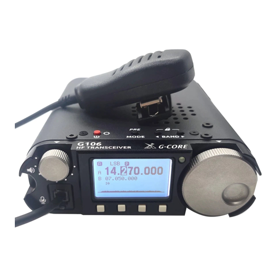
- Page 1 XIEGU HF Portable Transceiver G106 Operation Manual V1.40 Chongqing Xiegu Technology Co., Ltd.
- Page 2 G106 is a 5W portable QRP model with SDR circuit structure which uses 16bit-CODEC sampling and can deliver superior performance. The whole machine has SSB/CW/AM three modes and extra WFM (88~108MHz) receiving function, allowing you to listen to local FM broadcasts while communicating. Equipped with a CW digital filter with three bandwidths, it can help you connect to more and farther radio stations.
-
Page 3: Panel Buttons
Panel Buttons 1. Volume knob 4. T/R indicator Turn the knob to increase or decrease the volume. Status indicator Short-press to switch the built-in/ hand microphone speaker. 5. Main knob 2. Hand microphone interface Turn the knob to change the current frequency value; External hand microphone interface 6. - Page 4 Panel Buttons 7. Power button/ screen backlight brightness 9 and 10. Band switch button/ lock/ Ts Step ● Long-press the button to power on/ off. ● In the HF band, short-press these buttons to switch between frequency bands. ● Short-press the button after power on to turn on/ off the display backlight ●...
- Page 5 End Interfaces 11. Antenna interface 14. Ground nut BNC interface with an impedance of 50Ω For grounding cable of equipment 12. KEY interface 14. COM Interfaces 3.5mm stereo socket (3-wire), used to connect a manual Communication interface key or an automatic key (see Page 5 for the definition) 15.
- Page 6 Instructions for External Interface Connection 1. MIC interface 4. Key wiring diagram Front Panel Facing G106 Note: There is a bias voltage at the MIC end, so it shall not be short-circuited. 2. COM interface 3. ACC interface...
- Page 7 Connection of External Power Supply 9-16V external DC power supply can be used for G106. The current load capacity of DC power supply shall be at least 3A. Attached power lines can be used to connect to radio and DC power supply.
- Page 8 EMC ferrite bead can be applied on power lines to prevent external disturbance from entering radio via power lines and radio-frequency interference in radio from radiating externally via power lines when external power supply is adopted for G106. Ferrite bead shall be installed at the side closing to power plug to greatest extent.
- Page 9 Operation G106 calls various functions through the multi-function menu. All functions are allocated to different menu pages and there are 4 function options on each page. The menu items can be switched and called out in the following way: ● Short-press any multi-function button to call out the menu and turn the main knob to switch between the five menu pages in turn.
- Page 10 Multi-function Menu Items List of multi-function menu: Menu Page Menu Item Frequency/ channel mode VFOA-VFOB switching Memory channel Erase memory channel CW filter selection CW sidetone CW dot-to-dash ratio QSK switch Automatic key rate Key mode IAMBIC mode Startup information settings Pilot frequency mode Display mode Keypad tone...
- Page 11 Operation G106 uses a black and white dot matrix display screen to display all the status information of the whole machine, which is user- friendly. The visibility in outdoor sunlight is also very good.
- Page 12 Basic operation Turn on/ off the radio Operation methods: 1. Short-press the power button to power on the G106 in the power-off state. 2. Long-press the power button for about 2s to power off the G106 in the power-on state.
- Page 13 Operation Adjust the volume Operation methods: 1.Turn the volume knob to the left or right to adjust the output volume. 2.Short-press the volume knob to switch between built-in speaker and hand microphone speaker. Operating frequency band and mode selection Operation methods: 1.
- Page 14 Operation Set operation frequency Operation methods: TS step selection TS step selection can be realized by the BAND buttons and the operation method is as follows: Long-press the BAND left or right button for 2s to step up or down. Adjust the frequency 1.
- Page 15 Operation Inter-frequency transceiver SPL There are two independent VFOs inside the G106 transceiver, which can set different frequencies and modes respectively. Operation method: 1. Call up the multi-function menu [1/5] and select the A/B function to switch between VFO-A and VFO-B.
- Page 16 Operation Transmit in CW mode Insert the straight key or morse key into the KEY interface at the end of the G106 (see Page 5 for the definition of wiring) Operation methods: 1. Insert the morse key plug into the KEY port;...
- Page 17 G106 supports the amateur data communication mode, and supports the function control of the radio station by the computer software. Operation method: 1. Use the DE-19 adapter to connect the G106 to the computer (see page 21 for wiring definitions). Once communication with the computer is established, the character "C" will be displayed at the top of the screen.
- Page 18 Operation FM radio operation G106 can receive FM broadcast and the operation method is as follows: 1. Call the multi-function menu [5/5] and select the WFM function to go to the FM radio interface. 2. Functions of buttons: ① </> button at the bottom of the screen: Up and down to automatically search for radio stations. Automatically store the radio station found and stop.
- Page 19 Set startup display information The radio station call sign of G106 can be edited and displayed on its startup interface. Operation methods: 1. Call the multi-function menu [3/5] and select the CSN function to go to the information editing interface.
- Page 20 BSM band selection G106 can choose to switch frequency bands in sequence in all frequency bands, or only in amateur frequency bands. The operation methods are as follows: 1. Call the multi-function menu [5/5], select the BSM function, and enter the frequency band selection.
- Page 21 Operation MG hand microphone gain adjustment G106 can set the microphone gain of the hand microphone, the operation method is as follows: 1. Call the multi-function menu [5/5], select the MG function, and enter the handset gain setting interface. 2. Rotate the main knob to set the gain parameter. After selection, press SAVE to save and exit, the parameters will take effect.
- Page 22 View software version information Operation methods: 1. Call the multi-function menu [4/5] and choose the VER function to go to the firmware version information display interface. The displayed information is as follows (example): 2. Press any button to exit the current interface. Restore factory default parameters Method: In the off state, press and hold the MODE button to power on.
- Page 23 L4001 cable ACC cable DE-19 adapter (optional) G106 can be connected to computer and XPA125B through DE-19 adapter, which is convenient for data communication and power expansion. 1. Complete the connection as shown in the figure above. 2. The CH342 port driver shall be installed, or the driver tool may be used to install it online.
- Page 24 Appendix 1 Computer control instructions G106 adopts C-IV instruction sets. You can remotely control the transceiver based on standard instructions of the instruction set or configure control instructions of other software to enable the control over G106. Wave band voltage data The ACC interface of G106 provides wave band data of four frequency bands, which can control the peripheral device to automatically switch the wave band or identify the wave band information for other devices.
-
Page 25: Specification Parameters
Specification Parameters Specifications Receiving frequency: 0.55~30MHz 88~108MHz (WFM) Transmitting frequency: 3.5~3.9MHz 5.3515~5.3665MHz, 7.0~7.2MHz 10.1~10.15MHz 14.0~14.35MHz 18.068~18.168MHz 21.0~21.45MHz 24.89~24.99MHz 28.0~29.7MHz Operating mode: SSB/CW/AM , WFM (receive only) Receiving sensitivity: CW: 0.25uV @10dB S/N SSB: 0.5uV @10dB S/N AM: 10uV @10dB S/N Frequency stability: ±1.5ppm within 30min after power on @25°C: 1ppm/hour... -
Page 26: Packing List
1 copy USB data cable 1 pc. *Optional supporting products ■ DE-19: external USB communication adapter (applicable to G90, G90S, G106), which can be used for computer control and data communication. ■ XPA125B: 100W power amplifier and antenna tuner AIO ■... - Page 27 Copyright Statement Copyright © 2022 All rights are reserved by Chongqing Xiegu Technology Co., Ltd. Reproduction of any part of this Manual without permission is prohibited. ----------------------------------------------------------------------------------------------------------------------------- V1.40 XDC-A00...
Need help?
Do you have a question about the G106 and is the answer not in the manual?
Questions and answers