
Related Manuals for SDT Vigilant


Summary of Contents for SDT Vigilant
- Page 1 USER MANUAL Version 3 – 2021 © SDT International. All rights reserved. Specifications are subject to change without notice.
-
Page 2: Table Of Contents
Introduction ............................14 Design ............................15 External appearance ..........................15 Standard model............................ 15 Indicators ............................. 15 Specifications ..........................17 Vigilant-Permanent ..........................17 Installation ..........................19 Mechanical assembly ........................... 19 Electrical installation ........................21 Connectors ............................21 Power supply ............................21 Ground connection .......................... - Page 3 Modbus master ............................ 77 12.7 Modbus slave ............................80 12.8 OPC ..............................82 12.8.1 About OPC ................................82 12.8.2 OPC UA client in Vigilant ............................. 83 12.8.3 OPC endpoints ..............................83 12.8.4 OPC nodes ................................84 12.9 Techniques ............................87 12.10 Images ..............................
- Page 4 12.16.1 Information ..............................102 12.16.2 Mimic Label ..............................102 12.16.3 Signal ................................102 12.16.4 Elements ................................103 12.16.5 Alarms ................................103 12.17 Processing Modes ..........................104 12.17.1 Information ..............................106 12.17.2 Waveform ................................. 107 12.17.3 Spectrum ................................107 12.17.4 Filter ................................. 108 12.17.5 Elements ................................
- Page 5 13.5.3 Types of graphs ..............................149 13.5.4 Access to trends chart ............................150 13.6 Mimic ..............................150 13.6.1 Configuration ..............................150 13.6.2 Display ................................151 13.6.3 Points Visualization............................152 13.7 Trends ..............................152 13.7.1 Configuration ..............................152 13.7.2 Display ................................153 13.7.3 Zoom tools ................................
- Page 6 14.2 Periodic inspections ........................... 191 14.3 Reboot ............................... 192 14.4 Rescue mode ............................192 14.5 Micro-SD card maintenance ......................193 14.6 Replacement of internal components ....................193 14.6.1 Access to the rear compartment ........................194 14.6.2 Battery replacement ............................195 14.6.3 Fan replacement ...............................
-
Page 7: Introduction
SDT International sa-nv • Bd de l’Humanité 415 • B-1190 Brussels (Belgium) • Tel: +32(0)2 332 32 25 • info@sdtultrasound.com SDT North America • 7677 County Road 2, Cobourg, ON K9A 0X4 (Canada) • Phone: 1-800-667-5325 | 1-905-377-1313 • hearmore@sdtultrasound.com... -
Page 8: Support And Contact Details
If you experience a problem with a Vigilant unit, please, review the information contained in this manual. You can also contact our Customer Service and helping in getting your Vigilant unit up and running by calling to this number: 1-800-667-5325. -
Page 9: Standards
If you have purchased SDT branded electrical or electronic products in the EU and intended to discard these products at the end of their useful life, please do not dispose of them with your other household or municipal waste. - Page 10 Vigilant User Manual Instead, please be aware that SDT makes a return and collection system available to you, free of transportation and reuse and/or recycling costs. Please contact SDT on the following address: SDT North America Toll Free: 1-800-667-5325 Phone: 1-905-377-1313...
-
Page 11: Safety Information
Before starting the installation, work read the instructions delivered with the equipment. Stop the installation work if you have any doubt and contact your distributor or SDT for assistance. Be sure that main power is off and will stay off until the installation work ends. -
Page 12: Environment And Enclosure
Soldering the conductor is forbidden. 4.3 Environment and enclosure The Vigilant modules supplies as “open type” devices, meaning it should be installed in an enclosure suitable for the environment conditions present and prevent any damage to personnel. See NEMA or IEC standards for further information about the degree of protection provided by the different types of enclosures. -
Page 13: Batteries And Battery Charging
4.6 Batteries and battery charging The Vigilant has a rechargeable internal lithium-polymer battery as its auxiliary power supply. The integrated battery recharges automatically when the device is connected to the main DC power adaptor. The equipment battery is assembled inside, under a cap located in the back of the instrument and closed by screws. - Page 14 Vigilant User Manual Do not use the equipment if it presents damage after transportation or storage due to improper or careless handling. Please place it in a location free from direct sunlight, high temperature or humidity, or the corrosive environment when storing the equipment. See...
-
Page 15: System Description
Vigilant is a smart solution for protection, condition monitoring and failure mode identification of critical machinery. It can work as a standalone system, it does not require a permanent connection to a computer or software, while still measuring and protecting the equipment, storing data or even communicating scalar measurements to other systems via Modbus-TCP protocol. -
Page 16: Design
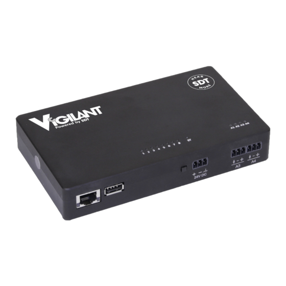
All these terminals are to be connected only to SELV-LPS (safety low-voltage) lines. Vigilant also has an RJ45 jack port on the left part of the case’s front for Ethernet communications (100Base-TX). The Ethernet port is to be connected only to indoor routed networks. - Page 17 Vigilant User Manual Solid blue Unit is on and ready. Power supply is ok. Solid red Unit is in rescue mode. Ethernet Yellow or Link/Activity connector green Input ports The input channel is either disabled, or if enabled, it is (Any type) processing the sampling data.
-
Page 18: Specifications
Vigilant User Manual 7 Specifications 7.1 Vigilant-Permanent The following table shows the specifications for the large version of the Vigilant device: High Speed Inputs Number of high-speed inputs HS Inputs sampling rate 512 to 51200 Hz DC Range ±24 V... - Page 19 Vigilant User Manual Filter types Butterworth, Bessel, Chebyshev Number of averages 1 up to 32 Overlap 0% up to 99% System General Features Internal Storage (OS) 4 GB Main CPU ARM Cortex™-A9 Quad Core (NVIDIA® Tegra™ 3) CPU clock 1.4 GHz...
-
Page 20: Installation
The following table describes the steps for assembling or removing the Vigilant from the DIN rail. To fasten the Vigilant onto the DIN rail, align it with the DIN rail connector, press firmly on top and push the lower end into position. - Page 21 Vigilant User Manual by all components within the enclosure, installing a forced ventilation system if required. Allow some free space around the air input grid and equipment’s fan output to ensure its proper cooling. To improve its cooling, remove any insulation material close to the unit and confirm the free circulation of air around the device.
-
Page 22: Electrical Installation
Vigilant also has a RJ45 jack port on the left part of the front of the case used for Ethernet communications (100Base-TX). The Ethernet port is to be connected only to indoor routed networks. -
Page 23: Ground Connection
9.3 Ground connection All the connectors for the main analog inputs of the Vigilant, and the power input connector, have a terminal for chassis ground connection. All those terminals are connected in between and, in turn, both to the Vigilant case and the DIN rail clip. -
Page 24: Main Inputs
The DIN rail can be grounded connecting it directly to the ground bus (as shown above), or by using a rail grounding terminal (shown below). 9.4 Main inputs The main inputs or high-speed inputs of the Vigilant share the following configuration: 23/210... -
Page 25: Iepe Transducer
Vigilant User Manual These inputs admit voltage signals in the range of ±24 V (24 Vpp in AC mode). They have been designed to accommodate fast signals coming from sensors like accelerometers, tachometers or displacement probes. Of course, they can also read slower signals like temperature probes or others. -
Page 26: Periodic Pulse Signal (Tachometer)
Vigilant User Manual It is recommended to use a shielded cable to avoid noise in the signal, as shown above. Ensure this shield is grounded. To avoid loops and noise, make sure just one of the cable's sides connects to ground. Typically, grounding is done in the cabinet side. -
Page 27: Ma Input Signal
Many sensors in the market can use the current loop for powering themselves, without needing any other power source (passive loop). However, the terminals of the Vigilant do not have the possibility of powering the sensors in that way. Thus in between the sensor and Vigilant must add an external power source: It is recommended to use a shielded cable to avoid noise in the signals. -
Page 28: Conmonsense Sensor 0-10V
CONMONSense Sensor 0-10v 9.5 Auxiliary inputs The connectors for the auxiliary analog inputs available in the Vigilant-P has the following configuration: The auxiliary inputs admit voltage signals in the range of ±24 V and design to read analog signals at slow rates. -
Page 29: Periodic Pulse Signal (Tachometer)
Vigilant User Manual As it is shown in the image, all the auxiliary inputs connectors include a signal ground (0V reference) terminal. All those terminals, labeled as “-”, are connected internally to the circuit 0V reference, and they are also in electrical contact with the negative terminal of the power input. -
Page 30: Ma Signal
Vigilant User Manual In case the sensor has a PNP output, the connection would look like this: 9.5.2 4-20 mA Signal Dynamic inputs can be configured to measure 4-20 mA current loop signals. This kind of current loop is an industry-standard used in many applications. They have the advantages of simplicity and noise immunity and have a large international user and equipment supplier base. -
Page 31: User Interface
• Connect the Vigilant to your device or network using an Ethernet cable. • Find out the IP address of the unit. By default, the Vigilant is supplied with the following IP address: 192.168.0.150. • Change the IP address of your device, so both are in the same logical Ethernet network (netmask). -
Page 32: Navigation Bar
Vigilant User Manual 10.3 Navigation bar The following picture shows the navigation bar, the main toolbar for the User Interface and its components. It appears at the upper part of the web page and shares by all the different modules of the interface: 10.3.1... -
Page 33: Application Status
Vigilant User Manual If the configuration tree is hidden, then the alarm toolbar will be located on the left, in vertical direction: 10.3.2 Application status The navigation bar shows in this area the application’s parts in which we are currently located. -
Page 34: Special Unit Indicator
Vigilant User Manual Clicking on the icon will show a more descriptive message for the specific event. Usually, those events may be: • Software Licenses are about to expire. • Storage capability of the system is reaching its limit. •... -
Page 35: User
From firmware version 0.8.0 the manual of the Vigilant is no longer integrated in the embedded application. Since the manual is on the website of Vigilant, you will need to have direct internet connection in order for this link to work properly. -
Page 36: Basic Interface Elements
Vigilant User Manual Field Description Full name Defines the name that will be shown for this user on the interface. Selects the language in which the interface will be shown for that user. Language Currently the languages available are: English and Spanish. - Page 37 Vigilant User Manual Users can edit those fields inside a box and with a white background indicated. Those fields with gray background or outside of a control box indicate they are just informative. On the other hand, those fields with an asterisk by its label indicate that they must fill in; otherwise, the changes in the form will not be accepted.
-
Page 38: Lists
Vigilant User Manual Clicking on the button “…” will show the list for the corresponding type of component. 10.4.2 Lists Lists provide a set of rows, which refer each of them to an item or object (machines, sensors, users, alarms, etc.). The following picture shows an example of a list: Elements of the list can be edited by clicking on any of those. -
Page 39: Expression Editors
Vigilant User Manual A modal form will appear, enabling the user to select a file. The interface allows the lists to be ordered by the user. This can be done using the Move- up and Move-down buttons. 10.4.3 Expression Editors... -
Page 40: System Settings
Vigilant User Manual 11 System Settings 11.1 Introduction The System Settings interface provides information about the status of the Vigilant, and allows the user to configure some properties related to system administration, connectivity, data storage, user management, etc. 11.2 Menu Tree... -
Page 41: Status
Allow loading and managing simulation archives, which are special sound format files (WAV) used to simulate machine vibration files. Licenses Shows a list with all the different modules of the Vigilant and inform if they are enabled in the unit or not. Upgrade Show the firmware version and check if a new firmware is available. - Page 42 Shows the local date and time. The unit reads the location from the device that shows the interface. Uptime This field indicates the time elapsed since the Vigilant unit was turned on. Configuration This field indicates the last date and time when a new measurement.
-
Page 43: Users
Vigilant User Manual 11.4 Users This form shows a list of the users currently defined on the Vigilant unit. Clicking on one of them will edit the user options. Click on the New button to create a new user. Field... -
Page 44: Host
Clicking on the Delete button will delete the user. The interface will ask for confirmation. 11.5 Host Defines the name and description and hostname of the Vigilant unit. The user can change them to correctly identify the unit. Label... -
Page 45: Time
Vigilant User Manual Field Description Static Allows the user to configure the static IP address of the Vigilant. If not checked the Vigilant unit will try to get its IP using DHCP protocol. Address Configures the IP address of the unit. -
Page 46: Services
This button is only shown when the ”Enable NTP” checkbox is unchecked. 11.8 Services This section allows configuring the 3 types of services that the Vigilant integrated: Remote Backup and E-mail Notifications. Some of these services require special network configurations,... -
Page 47: Remote Backup
The Remote backup service allows periodic backup copies of all the information and configurations contained in the Vigilant. Currently, the system only enables the possibility to create backups in the Vigilant network. This service guarantees the user a higher level of security about the integrity of its measurement data. - Page 48 Select which email server to use for the notifications. In case of SMTP Server selecting Default, the Vigilant server will be used, and most of following fields won’t be necessary. Port Usually SMTP works with port 25, but it can also work with 587.
-
Page 49: Rsync And Ftp Services
The FTP service provides a way to upload and download files into or from the Vigilant unit. Like the Rsync service the Vigilant unit works as a FTP server, so requires an FTP client in your computer to use this service. The Vigilant shares through FTP the folders where all the data and configuration files are stored. -
Page 50: Storage
Micro-SD card maintenance section for more details. This form allows setting the Vigilant strategy to erase old Snapshots when the number of records has reached its limit (10000 records is the maximum by default) or when the external flash memory is getting full. -
Page 51: Records
If the storage device (micro-SD card) is not in use, i.e. it is disabled, this menu will remain inactive. The Vigilant stores the data in its internal flash memory using different file formats. All information related to a set of measurements of the machine taken simultaneously (monitoring period) is stored together, in what we call Snapshots. - Page 52 At the top of the form, a bar graphically displays the memory percentages used for each of the storage formats. Field Description Machine Shows the list of machines that have been configured on the Vigilant and have any unit. Processing In the case of long-wave records, they separate depending not only on Mode the machine but also the original Processing Mode related to the storage.
-
Page 53: Backups
While executing this process, the following screen will be displayed until the database is ready again to be used: 11.11 Backups This form shows the list of backups of system data currently available in Vigilant network. The following information is shown for every file: •... -
Page 54: Simulation Files
Appendix A to get more information about how to generate your simulation files. 11.13 Licenses Shows a list with all the modules or features that have activated for this specific Vigilant. Please refer to Appendix B about Optional software features to see the complete list of available modules. -
Page 55: Upgrade Firmware
If the code is right, the corresponding licenses will activate, and the device will resume its regular operation after restarting. 11.14 Upgrade firmware This form shows the current firmware version of the Vigilant unit and allows upgrading it to the last version available. See the chapter about Upgrading the firmware to learn more about this process. -
Page 56: System Maintenance
11.16 System maintenance The System maintenance menu can be accessed through the icon on top of the System menu: This section allows user restoring the default settings of the Vigilant units and importing and exporting user and system configuration files. -
Page 57: Main Configuration
Exports into a file called conf.db the information related to the machines and measurements configuration: points, parameters, processing modes, sensors, etc. Import Imports into the Vigilant unit the conf.db file containing all the configuration settings for a machine or group of machines: points, processing modes, parameters, sensors, etc. 11.16.2... -
Page 58: Configuration
12 Configuration 12.1 Introduction In this section shows how to configure the Vigilant unit’s monitoring options, including its Inputs, Sensors, Machines, Points of measurement, Processing Modes, Storage Strategies, etc. It describes the Configuration interface, its usage and defines all the available fields and concepts in the system for a correct monitoring configuration. -
Page 59: Processing Blocks
The Processing Blocks are a way to measure the device’s capability to execute simultaneous operations with the data coming from the different inputs. Each input of the Vigilant unit can link to a measurement Point. If the Point is Dynamic type, it can have different Processing Modes .The data coming from the sensor is analyzed simultaneously in... -
Page 60: Inputs/Outputs
Apply configuration button is clicked. 12.2 Inputs/Outputs This menu allows configuring the input and output channels of the Vigilant device. By clicking on this option, the interface will show the inputs. Field... - Page 61 Vigilant User Manual Simulation Selects a file containing a simulation signal that will replace the input signal for that channel. The simulation signal contained in the file will be replayed continuously. Path Indicates the actual Machines and measurement points that are using this analog input to acquire monitoring data.
-
Page 62: Sensors
12.3 Sensors This section configures the sensors that will be connected to the Vigilant inputs. By clicking on this menu option, the interface shows the list of sensors available on the unit. Click on one of the items of the list to configure the corresponding sensor. -
Page 63: Conmonsense Sensor 0-10V Configuration
Vigilant User Manual 12.3.1 CONMONSense Sensor 0-10v Configuration Sensor configuration a. When you are logged to your Vigilant, navigate to the Sensors menu under the Configuration. b. Create a new sensor by clicking the New button. 62/210... - Page 64 Vigilant User Manual c. Fill the fields with the following values: • Name: does not really mater, you can use any name that helps you to identify the sensor. Here we use CONMONSense. • Others non-mandatory fields (description, manufacturer, model, serial number) do not mater and you can fill them with whatever you think useful for your needs.
-
Page 65: Input Configuration
Vigilant User Manual Input configuration a. Navigate to the Inputs/Outputs menu and click on the input number physically connected to the sensor (for this example we assume that the CONMONSense sensor is connected to the input 1) • Input mode: Dynamic •... - Page 66 Fill the fields with your machine information (all non-mandatory fields are optional) and make sure than both Enabled check boxes are checked. You can also modify the monitoring Period. It sets the time between 2 data acquisitions (for more information please refer the the Vigilant user manual).
- Page 67 Vigilant User Manual ↓ d. Set a name to identify your measurement point and select the input associated to this point. 66/210...
- Page 68 Vigilant User Manual e. Navigate to the Processing modes For this example, we will create 3 processing modes: o Spectrum and waveform o Demodulation o Long Waveform • Spectrum and waveform o Tag: use a name to identify the processing mode o Max.
- Page 69 Vigilant User Manual • Demodulation o Tag: use a name to identify the processing mode o High-Pass freq.: 500 [Hz] o Max. frequency: 500 [Hz] o You can modify the Bins and Averages in accordance to your needs as long as you...
- Page 70 Vigilant User Manual • Long Waveform o Tag: use a name to identify the processing mode o Sample rate: 12800 [Hz] o Maximum duration: configure the desired dynamic waveform duration. Define Parameters For each processing mode a set of parameters can be configured. We will configure 3 of them for the Waveform processing mode •...
- Page 71 Vigilant User Manual ↓ You can choose and configure the parameter and defining the limit values as well as the alarms according to your application needs. 70/210...
- Page 72 Vigilant User Manual Steps are the same for all other parameters. g. Navigate to storage and create a new Storage strategies • Select the storage period and the data you want to save. • Validate by clicking the Accept button.
-
Page 73: Information
Vigilant User Manual h. Apply the whole configuration by clicking the Apply button. 12.3.2 Information Field Description Name Identifies unequivocally the sensor. It can contain numbers, upper and lower characters. Special characters or blank spaces are not allowed. Description This field provides a description of the sensor. -
Page 74: Limits
Vigilant User Manual Sensitivity Sets the sensitivity of the sensor in volts per engineering units, as defined in the previous field. Bias voltage Value in volts of the signal offset provided by the sensor. AC detector Defines the detector type (if any) associated with the value measured for the static signal (RMS, Peak, Peak-Peak or none). -
Page 75: Units
Sets the number of harmonic lines to show on the spectrum. harmonics 12.5 Units This option defines the Properties and Units that will be available on the system and may be linked to the Sensors. The Vigilant comes with a list of factory predefined properties: 74/210... - Page 76 Vigilant User Manual New properties (e.g. a chemical concentration of any substrate) can be defined by the user. The system also includes a set of predefined units, linked to the above properties. New units may be defined for the predefined properties and for the new properties defined by the user:...
- Page 77 Vigilant User Manual The predefined Properties and Units are read only and cannot be deleted or edited (except dB reference field of the Units). Those created by the user may be erased by pressing on the Delete button. The following form shows the fields that define a new Property.
-
Page 78: Modbus Master
(Optional software features). This menu defines the external devices that will act as Modbus servers, and also the internal registers in those devices that will be read by the Vigilant. 77/210... - Page 79 Vigilant User Manual The menu includes two separate forms that allow the configuration of external Modbus data sources. The first form shows the fields that define the external Modbus servers: Option Description Name Identifies the Server unequivocally. It can contain numbers, upper and lower characters.
- Page 80 Vigilant User Manual Port Number of TCP port that the server has reserved for Modbus communications. By default, the port number is 502. Slave Id Slave number of the server in the Modbus network. Poll period The reading of the Modbus registers on each server will be done on specific periods defined by this parameter.
-
Page 81: Modbus Slave
Big Endian format. Using the swapping options, it is also possible to read numbers Little Endian format. 12.7 Modbus slave This option configures the Vigilant device as a Modbus server, allowing external systems the access to any internal variable. 80/210... - Page 82 Vigilant User Manual Access to the Modbus registers must be done using the Vigilant IP address in the local network and the TCP/IP port number 502. Slave ID number of the Vigilant is always 1. The menu includes three forms that allow setting up Modbus input register numbers to any element of the interface: •...
-
Page 83: Opc
OPC-based application can access as a client to read/write any variable offered by the server. Vigilant implements OPC-UA, which is the best-known evolution of the classic OPC technology. It is a cross-platform industrial communication technology, open, service-oriented, secure, and with rich information models that incorporates all the characteristics of classic standards but defining secure and platform independent communication mechanisms. -
Page 84: Opc Ua Client In Vigilant
12.8.2 OPC UA client in Vigilant The Vigilant allows to be used as an OPC-UA client allowing the connection to one or more OPC Endpoints to execute reading and/or writing services with one or more OPC Nodes... -
Page 85: Opc Nodes
Vigilant User Manual Option Description Name Identifies the Endpoint unequivocally. It can contain numbers, upper and lower characters. Special characters or blank spaces are not allowed. Description Text of description, for user notes only. Protocol Only the TCP option is allowed. - Page 86 Identifier: Identifier of the node that has to be unique within the space defined by the NamespaceIndex. See the following examples of OPC nodes: To define a new node in Vigilant user must enter the following fields of the form: 85/210...
- Page 87 Vigilant User Manual Option Description Name Name of the node. Description Optional detailed indication of the node content. Endpoint OPC endpoint previously configured. Node ID Identifier of the OPC node. To define the identifier of a node, V8 uses a XML notation whose format is: ` ns = <namespaceIndex>;...
-
Page 88: Techniques
Vigilant User Manual The assignment of OPC nodes as reading points for a machine is simple, and very similar to how it is done with the Modbus master. The user will simply have to create a new static type point and in the form select the OPC option and the node that you want to use as an input source. -
Page 89: Images
12.11 Machines Machines are the main objects for setting the monitoring configuration in the Vigilant unit. They are composed of different basic objects: Alarms, Components, Output connections, Points, Spectral Bands, States and Storage strategies. The configuration of all these basic elements within the machine defines the monitoring behavior of the unit. - Page 90 Tachometer: Those associated with a Pulse train input. • The data source of static and tachometer points may be a physical input of the Vigilant unit or a digital Modbus address. Spectral Bands Defines the different bands that will be used to configure the RMS value from the spectrum measurements.
- Page 91 Vigilant User Manual States Define the different machine conditions or states that the Vigilant unit will consider. They allow the user to define different Storage strategies and apply different alarm limits for the measurements depending on these machine states. Storage These elements define what measurements will the Vigilant store in the database.
-
Page 92: Information
Maximum length is 25 characters. Enabled Activates the machine for being shown in the interface. Disabling this option will cause the Vigilant unit to ignore the machine on the Dashboard. Name Text used on the Dashboard to identify the machine. -
Page 93: Monitoring
Period Sets the refreshing rate of the measurements in seconds. This is independent on the sampling time required for each Processing modes due to the Vigilant units’ pre-buffering capabilities. Delay Establish a certain amount of time to wait before starting acquisition after a configuration change. -
Page 94: Speed
Vigilant User Manual • Steam turbine sets with power greater than 50 MW and speeds below 1500 CPM or above 3600 CPM (not included in ISO 10816-2). • Rotary compressors. • Industrial gas turbines with power up to 3 MW. -
Page 95: Load
Vigilant User Manual The machine’s speed can also be calculated using the parameter “Frequency extraction” on a dynamic point. To use a parameter as a speed reference, the system needs to get it from an actual machine point. This may be accomplished creating a Static Point of Formula type and linking its value to the value of the frequency parameter. -
Page 96: Alarms
Vigilant User Manual 12.13 Alarms The machine alarms list allows quicker and easier access for the predictive maintenance analysts to more easily define the alarm levels for the different monitoring parameters defined for a specific machine. The alarms in this menu are the same as those in the lower part of the Parameters forms. -
Page 97: Components
12.15 Output connections The Output connections menu defines which outputs in the Vigilant are linked to this specific machine and how should they behave. This option could be useful, for example, for triggering external signals in case of an alarm. - Page 98 Vigilant User Manual The Outputs menu shows a list of the actual outputs that are linked to the machine, and allows creating more, as long as there are still free physical output ports available. When creating a new output for this machine, we will need first to select the type of output, depending on the actual outputs available at the instrument: •...
- Page 99 Vigilant User Manual Field Description Text that identifies the output. Text used on the Dashboard to identify the output. If none is given, the tag Name will be used. Description Allows the user to include a description of the Output.
- Page 100 Vigilant User Manual Field Description Text that identifies the output. Text used on the Dashboard to identify the output. If none is given, the tag Name will be used. Description Allows the user to include a description of the Output.
-
Page 101: Points
12.16 Points Points are the objects where all the measurements the Vigilant unit performs for the machine will be associated to. They are linked to an input source of data that bring information about the asset that is being monitored. - Page 102 Vigilant User Manual Clicking on one of the components will show its configuration form: 101/210...
-
Page 103: Information
Vigilant User Manual 12.16.1 Information Field Description Text that identifies unequivocally the point. Only ASCII alphanumeric characters are allowed, including ”.”, “-”, and “_”. Any other special characters or blank spaces are not allowed. First character must be alphanumeric. Maximum length is 25 characters. -
Page 104: Elements
Vigilant User Manual Source Selects the physical input (channel) of the Vigilant assigned to the Point or the Modbus address, depending on the type of signal selected in the previous field. Speed factor Factor that will be used to calculate the speed associated with the Point and its measurements. -
Page 105: Processing Modes
Dynamic Point can have multiple Processing Modes, e.g. with different sample frequency and other different parameters. All the signals in the Vigilant are always sampled at the same time, despite coming from different Points or Processing Modes, even if they are captured with different sampling frequency. - Page 106 Vigilant User Manual • Each Processing Mode of a Dynamic Point employs at least one Processing block. • Static Points do not consume Processing Blocks. Processing Blocks are a limited resource. Different versions of Vigilant may have a different number of them available (e.g.
-
Page 107: Information
Vigilant User Manual By clicking on one of the items of the list the interface will show the Processing mode specific configuration form. Anyhow, most of the fields are similar in the forms of the different types of Processing modes: 12.17.1... -
Page 108: Waveform
Vigilant User Manual Text that identifies unequivocally the Processing Mode. Only within a Dynamic point. Only ASCII alphanumeric characters are allowed, including: “.”, “-”, and “_”. Any other special characters or blank spaces are not allowed. First character must be alphanumeric. Maximum length is 25 characters. -
Page 109: Filter
Vigilant User Manual Duration Shows the actual duration of the original waveform needed to calculate the spectrum with user settings. It depends on number of bins, averages, overlap and filter settings. Buffer size Shows the number of buffer points needed to calculate the signal waveform. -
Page 110: Order-Tracking
Prebuffering Sets the amount of time prior to the capture event that will be stored with the rest of the signal. Takes advantage of the HW data buffers of the Vigilant. Maximum pre buffering duration is 30 seconds. 12.17.7 Order-Tracking... -
Page 111: Parameters
Vigilant User Manual 12.18 Parameters The Parameters define the scalar values that will measure in each Processing Mode. These parameters are calculated from the spectrum or from the waveform taken in the corresponding Processing Mode using different algorithm types or data processing. -
Page 112: Identification
Vigilant User Manual 12.18.1 Identification Field Description Text that identifies unequivocally the Parameter. Only ASCII alphanumeric characters are allowed, including ”.”, “-”, and “_”. Any other special characters or blank spaces are not allowed. First character must be alphanumeric. Maximum length is 25 characters. -
Page 113: Spectrum Rms
Vigilant User Manual Spectrum Measures a RMS value from the spectrum. It could either be calculated from the whole frequency content of the spectrum or by defining one or multiple bands. See parameter field Spectral bands. Calculated Measures the theoretical peak value from the RMS value, which in turn can... - Page 114 Vigilant User Manual Multiple Spectral bands can be associated with Spectrum RMS parameters. In those cases, the RMS value will be calculated using the frequency ranges defined on each of those bands. In the example below a parameter called “misalignment” was configured as Spectrum RMS type. The frequency...
-
Page 115: Alarms
Vigilant User Manual 12.18.4 Alarms The parameters allow defining different alarm values to be associated with the measurement. Field Description • Upper: alarm levels are above normal values. Type • Lower: alarm levels are below normal values. • Window: alarm levels are within a window. If values go outside the window the measurement will go into alarm. -
Page 116: Main Parameter
Vigilant User Manual 12.18.6 Main parameter In the Parameters menu, like in many other menus from Configuration web, there is a list with all the defined Parameters for that specific Point and Processing Mode. Like in similar lists for other elements, a couple of arrows next to the Delete and Copy buttons allow modifying the order of the Parameters in the list. - Page 117 Vigilant User Manual By clicking on one of the items the interface will show its configuration. There are three types of Spectral Bands that can be configured: Single Band, Harmonic Family and Sidebands. Type Description Single Band The single band type of spectral band defines a frequency range using a minimum and maximum frequency.
- Page 118 Vigilant User Manual Field Description Name Sets the unique name of the Spectral band. Description Defines the description of the Spectral band. Min. Sets the minimum frequency of the band. This value can be defined by Frequency introducing a value in Hz, or by the result of a formula, whose result will also be in Hz units.
- Page 119 Vigilant User Manual insert the variable or operator into the expression. The system checks automatically if the syntaxes of the expression are correct. If not, it shows an Invalid Expression message. These expressions make possible defining the frequency band as a function of the speed of the point, for example.
- Page 120 Vigilant User Manual Bandwidth Sets the width of the bands. This value can be defined by introducing a value in Hz or by the result of a formula, whose result will also be in Hz units. Click on Edit button to edit this field.
- Page 121 Vigilant User Manual The picture below shows the frequency ranges defined with this configuration above. Sideband This type of Spectral band defines a set of frequency ranges based on sidebands from a central frequency. Field Description Name Sets the unique name of the spectral band.
- Page 122 Vigilant User Manual Sideband Sets the distance in Hz between the sidebands. distance First sideband Sets the value of the first sideband. For example, a value of 3 will set as the first sideband a frequency of 3 times the sideband distance from the central frequency.
-
Page 123: States
Vigilant User Manual 12.20 States The States are objects included in the machine configuration that define the different machine conditions the Vigilant will consider. They allow the user to configure particular Storage Strategies and alarm limits depending on these different machine conditions or states. - Page 124 Vigilant User Manual The States are evaluated based on Logical Expressions . The evaluation of those expressions is done following the order of the machine State list. If one of the expressions is true, then the rest of the State expressions will not be evaluated. So that the machine will take the State whose expression comes true first.
-
Page 125: Storage Strategies
Vigilant User Manual Condition Sets the Logical Expressions that define the State condition. If the result is true, the machine will be set to that State. If not, the system will evaluate the expression of the following machine State. Click on the Edit button to introduce the expression using the form. -
Page 126: Identification
Vigilant User Manual 12.21.1 Identification Field Description Name Text that identifies unequivocally the Storage Strategy. Only ASCII alphanumeric characters are allowed, including ”.”, “-”, and “_”. Any other special characters or blank spaces are not allowed. First character must be alphanumeric. -
Page 127: Storage Settings
Vigilant User Manual Cron line Defines the expression of the Cron command. This expression sets the time when the storage event will be triggered. E.g.: • (every 5 minutes on Tuesday) cron */5 * * * tue • (every hour at hh:05) cron 5 * •... -
Page 128: Logical Expressions
Vigilant User Manual 12.22 Logical Expressions In many of the Configuration interface sections described in this chapter, it is possible to use logical expressions to build flexible rules to configure how the system behaves under specific environmental regulations. Output connections, machine... - Page 129 Vigilant User Manual “[POINT:]gerror” Error code in a sub-element of a machine or point. The error may be in one of the parameters, in case of the points, or also in one of the points, in case of the machine.
- Page 130 Vigilant User Manual Logical “and” Logical “not” Logical “equal as” Logical “not-equal as” >= Logical “greater or equal than” <= Logical “lesser or equal than” > Logical “greater than” < Logical “lesser than” Arithmetic subtraction Arithmetic addition Arithmetic multiplication Arithmetic power...
-
Page 131: Automatic Parameters
Vigilant User Manual 12.22.1 Automatic parameters Most of the parameters available for the logical expressions are those defined by the user in the configuration, but there are also others that are created automatically by the system in certain cases: Parameter Description Default parameter of a static point. -
Page 132: Dashboard
13 Dashboard 13.1 Introduction The Dashboard allows the user to display the data measured and/or stored on the Vigilant unit. It also shows the historical or currently active alarms present on the system. The Dashboard displays the data on windows called Widgets. The area where these Widgets are located is called Desktop. -
Page 133: Edit Desktop Layout
Vigilant User Manual On the example below the Dashboard is composed of 4 Desktops called General, Spectra, Trend and Waveform, and shows the layout and Widgets of the one called Spectra. The area below the Toolbar is used for placing the Widgets of the Desktop. It can contain multiple Widgets, and each of them can have a different size and be of a different type. -
Page 134: Split Widgets
Vigilant User Manual The following table defines the different options. Option Description Edit Name Edits the name of the Desktop. A pop/up window will appear. Introduce the new name and click on the Accept button to change the name or click on Cancel button otherwise. - Page 135 Vigilant User Manual The process can continue as necessary for each individual new Widget, to create the number of Widgets and layout required by the user. The split buttons will divide the Widget into 2 equal ones. The size of each one can be changed though by using the vertical and horizontal division lines.
-
Page 136: Merge Widgets
Vigilant User Manual 13.2.4 Merge Widgets The splitting of the Desktop changes can be reversed by using the Merge buttons. These buttons join 2 Widgets back into one. For merging two Widgets, they must have been splitted previously. It is not possible to merge... -
Page 137: Add Desktop
Vigilant User Manual Clicking on an empty one, a window will appear, showing the different type of Widgets available, and enabling to use the space for its functionality. Select the corresponding type of Widget that will be assigned to the corresponding window (spectrum on the example below). - Page 138 Vigilant User Manual When the database tree is not hidden this toolbar will be shown in horizontal, above the database tree. The active alarms are represented with circles, with a different color circle for each alarm level (from yellow to red for Warning, Alert and Danger).
-
Page 139: Configuration Tree
Vigilant. If any of the Parameters is in any alarm mode, a vertical mark on the left of the tree will identify it... -
Page 140: Global Play
The Global Play button will make the values of all the widgets to be updated automatically with the latest measurement performed by the Vigilant. The Play state will last for a few minutes, and after that will go back to Pause mode after a while, in order not to waste data bandwidth. -
Page 141: Keyboard Shortcuts Info
Vigilant User Manual Set to now Selects the machine of the measurements to be shown from the pull- down list. It is not even necessary to use this selection control. Once the Global Timeline function is enabled, just selecting one stored snapshot in the Timeline of any of the widgets, will do that all the other widgets go also to the same time moment. -
Page 142: Widgets
Vigilant User Manual 13.3 Widgets This Chapter describes the different type of Widgets. It shows how to work with them and its configuration options. Widgets can be added by clicking on any blank space in any of the Desktops of... -
Page 143: Widget Toolbar
The Timeline is a graphical tool that allows the user to access quickly to the measurements stored on the database of the Vigilant module. Clicking on this button: the Widget will show up the Timeline at the bottom part of the Widget. -
Page 144: Range Selection Timeline
Vigilant User Manual Range selection timeline In some other widgets, like the Waterfall, the Phase Diagram, or the Shaft Centerline behaves a little bit different, as it actually allows selecting a range of Snapshots to be represented in the chart (not... -
Page 145: Dynamic Cursor
Vigilant User Manual The alarm levels of the recorded data are calculated according to the settings when the data was stored. Those levels may have changed since then, and the interface may be showing incorrect alarm levels to those points, especially in Trends widget. -
Page 146: Parameter Matrix
Vigilant User Manual 13.4 Parameter Matrix This Widget displays in a matrix format all the parameters measured for each dynamic point of the machine. The Widget allows the user to see in a single view the current condition of a machine, with all the latest measurements and its alarms. -
Page 147: Display
Description The Play/Pause button will make the values of the parameter matrix to be updated automatically with the latest measurement performed by the Vigilant. Pause button will freeze the current values, so the parameter matrix will not be updated with new measurements. -
Page 148: Cell Colors
In any case, the pop-up window can be closed by pressing the ESC key. 13.5 Online Value This Widget displays the online value of a parameter measure on a dynamic input of the Vigilant. 13.5.1 Configuration The following picture shows its configuration settings. -
Page 149: Display
Vigilant User Manual Field Description Name Defines the name to the Widget. It will be shown at its upper bar. Machine Selects the machine of the measurements to be shown from the pull-down list. Point Selects the point of the measurement for that source from the pull-down list. -
Page 150: Types Of Graphs
Vigilant User Manual Symbol Description Shows/hides the global value information box. This box shows the following information associated with the measurement: machine name and speed. 13.5.3 Types of graphs The Online Value Widget may be configured to display the data in 4 different chart types: Simple, Horizontal bar, Vertical bar, and Meter. -
Page 151: Access To Trends Chart
Vigilant User Manual 13.5.4 Access to trends chart By clicking on the measurement value, the interface will present a window with the trend of the parameter. The graph will have all the options as the trend Widget. This window can be closed by selecting the corresponding button of the window or by pressing the ESC key. -
Page 152: Display
Vigilant User Manual Field Description Name Defines the name to the Widget. It will be shown at its upper bar. Machine Selects from the pull-down list the machine mimic to be shown. Show first Show value of the Main parameter below the label of the points. -
Page 153: Points Visualization
Vigilant User Manual Symbol Description Shows/hides mimic information boxes. This box shows the following information associated with the machine: machine name, speed, load, state, and alarm condition. 13.6.3 Points Visualization The measuring points defined for the machine will be shown in the mimic, represented with a label with its tag. -
Page 154: Display
Vigilant User Manual Line Color Selects the color of the trend line for the particular data source or measurement. Point Selects the point of the measurement for that source from the pull-down list. Param Selects the parameter or measurement to be plotted for that source from the pull-down list. - Page 155 Vigilant User Manual Symbol Description Sets the current range of the trend from the pull-down list. The time range available are 1 hour, 12 hours, 1 day, 3 days, 1 week, 1 month, 3 months, 9 months, 1 year. Trends Filter behaves similar as the timeline filter in other widgets. The button allows selecting which machine state and alarm status to show, and the rest of the points will get hidden.
-
Page 156: Zoom Tools
Vigilant User Manual Shows/hides trend information box. This box shows the following information associated with each trend: machine, point and parameter, along with the color line for each of them. Note that the coloured background of the graph is used to show information about the different machine states along time (when this option is activated in the configuration of the widget). -
Page 157: Waveform
Vigilant User Manual The click will show a pop-up window at the top right side of the Widget with some information about the point selected by the user: • Date and time when the point was measured. • Value of the signal in that moment. - Page 158 Vigilant User Manual Field Description Name Defines the name to the Widget. It will be shown at the upper bar of the Widget. Line Color Selects the color of the waveform line. Machine Selects the machine of the waveform from the pull-down list.
-
Page 159: Display
Vigilant User Manual Field Description Tacho edges Shows or hides vertical marks on the Widget indicating the position of the tachometer edges. The Machine needs to have a Tachometer point connected to a Pulse train input. Horizontal Shows or hides horizontal grid lines on the Widget. - Page 160 The Play/Pause button will make the values of the waveform to be updated automatically with the latest measurement performed by the Vigilant. The Play state will last for a few minutes and will go back to Pause mode after a while, in order not to waste data bandwidth.
-
Page 161: Zoom
Vigilant User Manual • Sync. Average: Shows a waveform composed of the average value of all the cycles in the original waveform (they are resampled to calculate the average). The displayed waveform will have all cycles to be identical. •... -
Page 162: Delta Time Cursor
Vigilant User Manual Once the cursor is created clicking on the graph again will move the cursor into the line of the waveform point aligned with the mouse click position. The cursor can also be moved by pressing on left and right arrows of the keyboard, jumping from line to line of the waveform. Keys “a” and “s” will move the cursor to the left and right respectively in smaller steps (a tenth of the waveform resolution). -
Page 163: Runout Compensation
(i.e. no dynamic movement of the shaft), so only the combined mechanical and electrical runout is seen. The Vigilant dashboard allows selecting any stored signal to be used as a Reference to apply runout compensation. Any stored signal that appears in the widget timeline can be selected, with the only condition that it contains a complete machine rotation cycle: that is, that there have been at least two equal tachometer flanks. -
Page 164: Synchronous View
Synchronous averaging is useful for waveform analysis especially in the case of gear drives. The synchronous averaging functionality of the Vigilant is limited, as it only allows averaging the waveform cycles contained in the waveform that has been recorded in a single capture. - Page 165 Vigilant User Manual Field Description Name Defines the name to the Widget. It will be shown at the upper bar of the Widget. Line Color Selects the color of the orbit line. Machine Selects the machine of the waveform from the pull-down list.
-
Page 166: Display
Vigilant User Manual filtered signal. Sub-harmonic values are indicated by introducing a fraction in the form (only rational numbers are valid). Max cycles Select a maximum number of rotating cycles to be displayed in the interface. Max samples per Selects the maximum number of sample points to show per machine... - Page 167 The Play/Pause button will make the values of the waveform to be updated automatically with the latest measurement performed by the Vigilant. The Play state will last for a few minutes and will go back to Pause mode after a while, in order not to waste data bandwidth.
-
Page 168: Zoom
Vigilant User Manual Exports the orbit values to CSV format and creates and downloads it into a local file. Shows/hides orbit information box. This box shows the sampling rate of the waveforms. 13.9.3 Zoom Use the mouse wheel to zoom in and out on the graph. The Widget will zoom around the cursor position is located on the plot, for both X and Y directions. -
Page 169: Configuration
Vigilant User Manual 13.10.1 Configuration The following picture shows its configuration settings. Once the Widget is selected click on the shortcut key “c” or the button in order to show its configuration form. Field Description Name Defines the name to the Widget. It will be shown at the upper bar of the Widget. -
Page 170: Display
Vigilant User Manual Field Description X-Axis Sets the frequency units of the spectrum. Select between Default, CPM, Hz or Orders. Default will use the units defined on the User Preferences. X View Sets the maximum and minimum values visible in the X axis. Note that clicking on the Reset zoom button with this option enabled will reset it to the values set in this form. - Page 171 The Play/Pause button will make the values of the spectrum to be updated automatically with the latest measurement performed by the Vigilant. The Play state will last for a few minutes and will go back to Pause mode after a while, in order not to waste data bandwidth.
-
Page 172: Zoom
Vigilant User Manual Sets the current cursor as a side band type cursor. This will show a center frequency and sidebands around it, each of them with the number of harmonics defined on the configuration of the Widget. Shows the waveform measured along with the spectrum, as defined in the configuration of the corresponding Processing Mode. -
Page 173: Cursors
Vigilant User Manual By selecting one of them the corresponding Fault Frequency will be represented on the spectrum plot as a dotted vertical line, along with its harmonics. The number of harmonic lines is defined on the configuration of the Fault Frequency. -
Page 174: Harmonic Cursor
Vigilant User Manual Harmonic cursor Once the cursor: is created, clicking on the graph again will move the cursor into the line of the spectrum vertically aligned with the mouse click position. The cursor can also be moved by pressing on left and right arrows of the keyboard, jumping from line to line of the spectrum. -
Page 175: Waterfall
Vigilant User Manual Once the cursor is on the correct frequency peak clicking again on the graph will set this frequency as the central one, which will be identified with a red vertical line, and add the side band cursor and its harmonics. - Page 176 Vigilant User Manual Field Description Name Defines the name of the Widget. It will be shown at the upper bar of the Widget. Line Color Selects the color of the waterfall lines. Machine Selects the machine of the spectra from the pull-down list.
-
Page 177: Display
Vigilant User Manual Bins The spectra represented in this widget are limited in the number of bins. The higher the number, the more time Dashboard will need to load the widget. This does not affect parameters and other calculations defined in Configuration. -
Page 178: Frequency Scale Selector
Vigilant User Manual Select standard rotation views. Toggle perspective/orthographic view. Toggle filled/transparent paths for the spectra (the area below the spectrum becomes opaque) Restores the zoom to its normal condition, removing the effect of any previous zoom done on the plot. -
Page 179: Long Waveform
Vigilant User Manual 13.12 Long Waveform This Widget displays a long waveform capture, using an envelope view instead of the full waveform (Optional software features). Different analysis tools allow decomposing this long duration signal, extracting spectra, parameters, etc. 13.12.1 Configuration The following picture shows its configuration settings. - Page 180 Vigilant User Manual Field Description Window Select type of window to calculate the spectra: • Rectangular. • Hann. • Hamming. • Blackman. Integrate Sets up if the data has to be integrated once or twice. Acceleration integrates to velocity, and this to displacement.
-
Page 181: Display
Vigilant User Manual Field Description Show RMS Shows or hides the trend of the RMS value along the waveform Horizontal Lines Shows or hides horizontal grid lines on the Widget. Vertical Lines Shows or hides vertical grid lines on the Widget. -
Page 182: Single Cursor
Vigilant User Manual Exports the long waveform to a WAV file and downloads it to a local file. Shows/hides information boxes. This box shows the sampling rate and number of samples in the waveform. 13.12.3 Single cursor The long waveform widget allows two cursor options, automatically selected with the mouse movements applied over the widget. -
Page 183: Configuration
Vigilant User Manual 13.13.1 Configuration The following picture shows the configuration settings of the Phase Diagram widget. Once the Widget is selected click on the shortcut key “c” or the button in order to show its configuration form. Field Description Name Defines the name of the Widget. - Page 184 Vigilant User Manual Peak Selects the detector to be applied to the peak amplitudes (RMS, Peak, Peak- Detector Peak) Phase View Configure how the angles are displayed in the phase view of the Bode plot. X Axis Configure to order the points in the X-axis using the timestamp or the speed of the machine (real Bode view).
-
Page 185: Display
Vigilant User Manual Vertical Shows or hides vertical grid lines on the Widget. Lines 13.13.2 Display The following picture shows the phase plots Widget and its components. Symbol Description Timeline: select which part of the storage will be used as source data for the phase plots. -
Page 186: Single Cursor
Vigilant User Manual Shows/hides mimic information boxes. This box shows the following information associated with the machine: machine name, speed, load, state and alarm condition. 13.13.3 Single cursor The Single cursor is selected by default in this widget. Clicking on any point of the graphs, this will show a pop-up window at the top right side of the Widget with the following information: •... -
Page 187: Display
Vigilant User Manual Field Description Name Defines the name to the Widget. It will be shown at its upper bar. Image size Sets the way the image fits on the space of the Widget: Normal shows the image at its normal resolution, Double increase 2 times the size of the image, Cover all fits the image file to the total space available on the Widget. -
Page 188: Configuration
Vigilant User Manual When a rotor system with hydrodynamic bearings changes speed or load, the stiffness and damping characteristics of the bearings are also modified. As a result, changes in the average radial position of the shaft will also be observed. -
Page 189: Display
Vigilant User Manual Field Description Horizontal Sets the maximum horizontal clearance that the axis is supposed to have (clearance) into the shaft area. Indicates the theoretical maximum displacement in X axis and sets the width of the shaft drawing. Vertical... -
Page 190: Single Cursor
Vigilant User Manual Symbol Description Timeline: select which part of the storage will be used as source data for the shaft centerline plot. SCL filter behaves similar as the filter in Trends. The button allows selecting which machine state and alarm status to show, and the rest of the points will get hidden. - Page 191 Vigilant User Manual • L (raw X): Horizontal position of the shaft center. Raw data, without clearance compensation. • L (raw X): Vertical position of the shaft center. Raw data, without clearance compensation. • “Set as zero”: Sets the selected point as the origin of coordinates, so that its position is used to calculate corrected positions.
-
Page 192: Maintenance
The device comes by default with a flash memory card with a total capacity of 4Gb. Although Vigilant is using industrial range SD cards with pSLC technology for this feature, and that minimizes the risk of data loss or corruption, the flash technologies used in micro-SD cards are subject to failure, and thus incidents with the SD storage are in the long term inevitable. -
Page 193: Reboot
Wait until the unit is initialized. 14.4 Rescue mode If the button located in the hole next to the power connector is pressed while the Vigilant is starting up, the unit will enter the rescue mode. Follow these steps to enter the rescue mode: •... -
Page 194: Micro-Sd Card Maintenance
Otherwise, please contact Vigilant if you need to replace the SD card of your system or if you are not sure about its integrity. In following chapters, it is explained how to perform a... -
Page 195: Access To The Rear Compartment
Vigilant User Manual This procedure refers exclusively to equipment with a hardware version equal or later than v1.3. That version was released to the public in July 2019. If your device is older than that, or you are not sure... -
Page 196: Battery Replacement
14.6.2 Battery replacement The Vigilant units carry an internal Lithium-Ion battery, which is used as an auxiliary power supply, which allows the clean shutdown of the operating system when the main power has been disconnected, allowing time to save the temporary data and index the bases of data. -
Page 197: Fan Replacement
The manufacturer will supply the necessary replacement unit. The fan used in the Vigilant has a life expectancy of more than 5 years working continuously at maximum power. Its replacement is an exceptional procedure and must be carried out with great care. -
Page 198: Micro-Sd Card Replacement
14.6.4 Micro-SD card replacement The Vigilant unit has an internal micro-SD card where all trend data, spectra, waveforms, etc. are permanently stored. The data is collected during normal operating measurements of the equipment. Other data such as measurement settings, system and users are also stored in the card. -
Page 199: Troubleshooting
14.7 Troubleshooting The following table shows solutions for possible trouble with this device: Symptom Possible Cause Description No communication The unit is off Turn Vigilant on by applying power to it. 198/210... - Page 200 Otherwise check cable connections. Network Check network configuration. IP address and configuration mask should be in the same range in both the Vigilant and the computer. Processor failure Restart the unit. The information is not Bad functioning Update the browser to the latest version. If...
-
Page 201: Basic Operations
Power supply. Once the unit is powered, it will start up. The Vigilant has a start-up period of several seconds. This time can vary from 10 to 15 seconds. The power led is used to indicate the status of the Vigilant during the start-up. During start-up, the status indicator will be turned on with a solid red color. - Page 202 Follow these steps in order to check for new versions and upgrading the firmware of the Vigilant: 1) Upgrade from server: Click on Check for new FW on server. If a new firmware version is available, click on Upgrade to begin with the installation.
-
Page 203: Creating Simulation Files
Vigilant User Manual 1. Appendix A 1.1 Creating simulation files Simulation files are raw (header-less) binary files with 16-bit signed integer samples recorded at 51200 Hz. You can create new simulation files using an audio editor. In the following instructions we will make a 440 Hz sine tone using the free audio editing software Audacity. -
Page 204: Optional Software Features
2. Appendix B 1.2 Optional software features Vigilant has a wide variety of optional software modules and utilities that allow the customization of the system to meet any particular requirement. There are available three predefined configurations: Supervisor, Diagnostic, Turbomachinery. The system may also be adapted to any specific needs, upon request, so customers only pay for the functions to be used. - Page 205 Vigilant User Manual Offline Upgrade firmware firmware using a local file upgrade Options marked with an “O” may be activated for any of the predefined configurations. 204/210...
-
Page 206: Network Ports
Vigilant User Manual 3. Appendix C 1.3 Network Ports 1.3.1 Incoming connections Port Service Description TCP 80 HTTP Web server TCP 443 HTTPS Web server (SSL support) TCP 21 FTP server for data backup TCP 873 RSYNC Rysnc server for data backup... -
Page 207: Keyboard Shortcuts
Vigilant User Manual Appendix D 1.4 Keyboard Shortcuts Action General escape Close modal window (one level). Show this panel. Show alarm log. Open or close the sidebar. Desktop ctrl + d Add a new desktop. Select the next desktop (in cycle). - Page 208 Vigilant User Manual Spectrum arrowleft* Move active cursor one sample left. arrowright* Move active cursor one sample right. Arrowup Find an approximated peak with respect to the cursor. Enter Start or stop data streaming. Move active cursor 1/10 sample left.
- Page 209 Vigilant User Manual shift + g* Move all cursors 1/10 sample right. Open or close timeline. Exit cursor mode. Reset zoom. Parameters enter Start or stop data streaming. Move active timeline cursor one event left. Move active timeline cursor one event right.
- Page 210 Vigilant User Manual Open or close timeline. Waterfall Arrowd Move down one layer. arrowleft* Move active cursor one sample left. arrowright* Move active cursor one sample right. arrowup Move up one layer. Change to next processing mode (in cycle). Show spectrum.
Need help?
Do you have a question about the Vigilant and is the answer not in the manual?
Questions and answers