Table of Contents
Advertisement
Quick Links
USER MANUAL
Version 4 – 2022
© SDT International. All rights reserved. Specifications are subject to change without notice.
SDT International sa-nv • Bd de l'Humanité 415 • B-1190 Brussels (Belgium) • Tel: +32(0)2 332 32 25 • info@sdtultrasound.com
SDT North America • 7677 County Road 2, Cobourg, ON K9A 0X4 (Canada) • Phone: 1-800-667-5325 | 1-905-377-1313 • hearmore@sdtultrasound.com
www.sdtultrasound.com
Advertisement
Table of Contents

Related Manuals for SDT VIGILANT


Summary of Contents for SDT VIGILANT
- Page 1 © SDT International. All rights reserved. Specifications are subject to change without notice. SDT International sa-nv • Bd de l’Humanité 415 • B-1190 Brussels (Belgium) • Tel: +32(0)2 332 32 25 • info@sdtultrasound.com SDT North America • 7677 County Road 2, Cobourg, ON K9A 0X4 (Canada) • Phone: 1-800-667-5325 | 1-905-377-1313 • hearmore@sdtultrasound.com...
-
Page 2: Table Of Contents
Vigilant User Manual Table of contents Introduction ............................. 6 1.1. Note to customer............................... 6 1.2. Symbols used ..............................6 Support and contact details ........................7 2.1. Sales and support contact ........................... 7 2.2. Installation assistance ..........................7 Standards..............................8 3.1. - Page 3 Modbus master ............................78 12.8. Modbus slave ............................81 12.9. OPC ................................83 12.9.1. About OPC ................................ 83 12.9.2. OPC UA client in Vigilant ..........................83 12.9.3. OPC endpoints..............................84 12.9.4. OPC nodes ................................ 85 12.10. Techniques ............................... 88 12.11.
- Page 4 Vigilant User Manual 13. Dashboard ............................149 13.1. Introduction ............................149 13.2. Dashboard Layout ........................... 149 13.2.1. Desktop Toolbar ............................. 149 13.2.2. Edit Desktop Layout ............................150 13.2.3. Split Widgets ..............................151 13.2.4. Merge Widgets ............................... 153 13.2.5. Select type of Widget ............................. 153 13.2.6.
- Page 5 Vigilant User Manual 13.13. Orbit ............................... 194 13.13.1. Configuration ..............................194 13.13.2. Display ................................196 13.13.3. Zoom ................................197 13.13.4. Single cursor ..............................198 13.14. Phase Diagram ............................198 13.14.1. Configuration ..............................198 13.14.2. Display ................................200 13.14.3. Single cursor ..............................202 13.15.
-
Page 6: Introduction
Depending on the options purchased with the equipment some of the functions described in this User Manual might not be available to you. If the Vigilant module combines with other instrumentation and then resold or transferred as part of assembly, be sure that following manual gives to the end user. -
Page 7: Support And Contact Details
If you experience a problem with a Vigilant unit, please, review the information contained in this manual. You can also contact our Customer Service and helping in getting your Vigilant unit up and running by calling to this number: 1-800-667-5325 or +32 (0) 2 332 32 25. -
Page 8: Standards
If you have purchased SDT branded electrical or electronic products in the EU and intended to discard these products at the end of their useful life, please do not dispose of them with your other household or municipal waste. - Page 9 Vigilant User Manual Instead, please be aware that SDT makes a return and collection system available to you, free of transportation and reuse and/or recycling costs. Please contact SDT on the following address: SDT North America Toll Free: 1-800-667-5325 Phone: 1-905-377-1313...
-
Page 10: Safety Information
Before starting the installation, work read the instructions delivered with the equipment. Stop the installation work if you have any doubt and contact your distributor or SDT for assistance. Be sure that main power is off and will stay off until the installation work ends. -
Page 11: Environment And Enclosure
4.3. Environment and enclosure The Vigilant modules supplies as “open type” devices, meaning it should be installed in an enclosure suitable for the environment conditions present and prevent any damage to personnel. See NEMA or IEC standards for further information about the degree of protection provided by the different types of enclosures. -
Page 12: Batteries And Battery Charging
4.6. Batteries and battery charging The Vigilant has a rechargeable internal lithium-polymer battery as its auxiliary power supply. The integrated battery recharges automatically when the device is connected to the main DC power adaptor. The equipment battery is assembled inside, under a cap located in the back of the instrument and closed by screws. - Page 13 Vigilant User Manual Protect the equipment against humidity during its transportation and storage, even when using the original packing. Do not use the equipment if it presents damage after transportation or storage due to improper or careless handling. Please place it in a location free from direct sunlight, high temperature or humidity, or the corrosive environment when storing the equipment.
-
Page 14: System Description
Vigilant is a smart solution for protection, condition monitoring and failure mode identification of critical machinery. It can work as a standalone system, it does not require a permanent connection to a computer or software, while still measuring and protecting the equipment, storing data or even communicating scalar measurements to other systems via Modbus, TCP protocol or API-rest. -
Page 15: Design
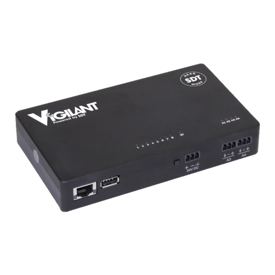
6. Design 6.1. External appearance At the front and back sides of Vigilant several pluggable terminal blocks allow connecting wires both for sensor signals and power supply. All these terminals are to be connected only to SELV-LPS (safety low-voltage) lines. -
Page 16: Indicators
Vigilant User Manual 6.3. Indicators The following table describes the light indications (LEDs) available on the front face: Color status Description Status White Entering power-up or power-down stage. Blinking blue Unit starting or shutting down in normal mode Blinking red... -
Page 17: Specifications
Vigilant User Manual 7. Specifications 7.1. Vigilant-Permanent The following table shows the specifications for the standard version of the Vigilant device: General Function Multi-channel acquisition system Operable with Provided sensors (voltage output) Main dynamic inputs 8 channels (for vibration and ultrasound) Auxiliary inputs 4 channels (ex: tachometer, temperature, etc.) -
Page 18: Additional Specifications With The Mobility Case
Vigilant User Manual Gain 0 to 42, range of +6 Points type Dynamic (preferred), Static, Tachometer Auxiliary inputs (A1, A2, A3 and A4) Sampling rate Up to 200 DC range ± 24 ADC resolution bits Power output Input configuration modes... -
Page 19: Installation
8. Installation 8.1. Mechanical assembly The Vigilant system was not designed as an “enclosed type” system. That means that it generally requires to be installed in an external enclosure prepared for the application site’s environmental conditions. The unit includes an accessory to be mounted on standard DIN rail (35 mm rail). Using the accessory installed at the back of the casing, it can be mounted on a DIN rail fastened to the mounting panel of the enclosure. - Page 20 Vigilant User Manual Outdoor installations are particularly susceptible to condensation. This should be avoided by installing the corresponding components within the enclosure. Direct sunlight and high ambient temperatures should be avoided. It is recommended to separate the unit from any external heat source that could cause high temperatures.
-
Page 21: Electrical Installation
±24V DC. That applies both for power and signal connections, including all inputs. Vigilant also has a RJ45 port on the left part of the front of the case used for Ethernet communications (100Base-TX). The Ethernet port is to be connected only to indoor routed networks. -
Page 22: Ground Connection
9.3. Ground connection All the connectors for the main analog inputs of the Vigilant, and the power input connector, have a terminal for chassis ground connection. All those terminals are connected in between and, in turn, both to the Vigilant case and the DIN rail clip. -
Page 23: Main Inputs
The DIN rail can be grounded connecting it directly to the ground bus (as shown above), or by using a rail grounding terminal (shown below). 9.4. Main inputs The main inputs or high-frequency inputs of the Vigilant share the following configuration: 23/232... -
Page 24: Iepe Sensor
Vigilant User Manual These inputs admit voltage signals in the range of ±24 V (24 Vpp in AC mode). They have been designed to accommodate fast signals coming from sensors like accelerometers, tachometers or displacement probes. They can also read slower signals like temperature probes or others. -
Page 25: Periodic Pulse Signal (Tachometer)
Vigilant User Manual It is recommended to use a shielded cable to avoid noise in the signal, as shown above. Ensure this shield is grounded. To avoid loops and noise, make sure just one of the cable's sides connects to ground. Typically, grounding is done in the cabinet side. -
Page 26: Digital Inputs
Many sensors in the market can use the current loop for powering themselves, without needing any other power source (passive loop). However, the terminals of the Vigilant do not have the possibility of powering the sensors in that way. Thus in between the sensor and Vigilant must add an external power source: It is recommended to use a shielded cable to avoid noise in the signals. -
Page 27: Auxiliary Inputs
3 = 0V (-) (Blue Cable Wire) 4 = Communication line (should be left floating if not used) (Black Cable Wire) The following diagram shows the wiring required for connecting the sensor to the VIGILANT: CONMONSE sensors are provided in a default configuration (dynamic mode, Gain = +60 dB) The appropriate gain of the sensor equivalent to “apparent sensitivity”... -
Page 28: Periodic Pulse Signal (Tachometer)
Vigilant User Manual The auxiliary inputs admit voltage signals in the range of ±24 V and design to read analog signals at slow rates. As it is shown in the image, all the auxiliary inputs connectors include a signal ground (0V reference) terminal. -
Page 29: Ma Signal
Vigilant User Manual In case the sensor has a NPN output type, the normal connection between the sensor and the auxiliary inputs would be something like this: In case the sensor has a PNP output, the connection would look like this: 9.5.2. -
Page 30: Conmonsense Sensor 0-10V (Static Mode)
9.5.3. CONMONSense Sensor 0-10v (static mode) Note that the sensor needs an external 24V DC supply capable of delivering at least 40 mA. Utilizing the power supply supplied with the Vigilant is acceptable or a separate dedicated power supply can be used. -
Page 31: User Interface
2 ethernet port, by default). Note 1: You can also access the VIGILANT Mobility case via WIFI. Find out the SSID of your unit then enter the default WIFI password: MQUdWNOm Note 2: The gateway (module RUT 240) is accessible at 10.8.2.1 (or 192.168.0.1):... -
Page 32: Navigation Bar
Vigilant User Manual Enter the username and password and click on “Sign in”. The Vigilant has a predefined Username assigned as “admin”. The default unique password is provided with the unit. Please refer to the documentation provided in the original package of the unit. The password is also printed on the label at the back of the unit. - Page 33 Vigilant User Manual If the configuration tree is hidden, then the alarm toolbar will be located on the left, in vertical position: The blue alarms relate to system alarm such as measurements that can be out of user-specifications. For example, this kind of alarms could be useful to indicate if the current measurement is beyond/above the specifications of the sensors.
-
Page 34: Interface Module
Vigilant User Manual 10.3.2. Interface Module The navigation bar includes on the right of the Configuration Tree button the Interface Module menu. By clicking on it this pull-down menu will show the different interface modules. The module currently active will be listed at the top, and will be shown on the toolbar when this menu is closed. -
Page 35: Device Status
In some cases, an indicator with a blue background will appear in the top bar indicating that the application is not a regular Vigilant unit. This indicates that the VIGILANT is a special demonstrative unit, with all the licenses/features activated but not intended to be used in commercial applications. - Page 36 Vigilant User Manual Menu option Description Preferences Access to the specific preferences (language and units) for the active user. Export Export a JSON file, in .dat format, containing the desktop layout configuration from desktops the active user and unit preferences. Save the dashboard settings.
-
Page 37: Basic Interface Elements
Vigilant User Manual Field Description Full name Defines the name that will be shown for this user on the interface. Language Selects the language in which the interface will be shown for that user. Additional languages will be progressively implemented using firmware updates. At the moment, the webserver interface is only available in English. -
Page 38: Lists
Vigilant User Manual Users can edit those fields inside a box that have a white background. Those fields with gray background or outside of a control box are just informative. The fields with an asterisk indicate that they must be filled in, otherwise the changes in the form will not be accepted and the system will return an error message. -
Page 39: Expression Editors
Vigilant User Manual Icon Description Moves the item of the list one position up. Moves the item of the list one position down. Deletes the item from the configuration database. A pop-up windows will ask for confirmation. Copies the item selected and creates a new one with the same options. The interface will show a pop-up window, requesting some information about the new item (Tag, Name, etc.). - Page 40 Vigilant User Manual its error status and some internal variables (timers, speed change, load change, etc.). By selecting one of the items of the list the corresponding variable will be inserted automatically on the expression field, helping in that way with the writing of the expression.
- Page 41 Vigilant User Manual • provides the alarm value of point B1V. "B1V:alarm" • provides the alarm value of point B1A. "B1A:alarm" • provides the alarm value of the parameter RMS of point B1H. "B1H:RMS:alarm" • provides the value of the parameter RMS of point B2V.
- Page 42 Vigilant User Manual Elapsed_t This internal variable provides the number of seconds elapsed since the last stored snapshot was captured. The value is initialized to 0 at startup or after a new configuration is applied. t_st (x) This variable provides the number of seconds spent by the Machine in that state since restart or since the last change made on the configuration.
- Page 43 Vigilant User Manual • Other positive integer value: An error has been detected. See Error codes. Point_tag:vbias Provides the value of the Bias or DC voltage of the input channel that was configured for that Point. Point_tag:param_ta This type of variable provides the value of the corresponding Parameter of the g:value Point.
- Page 44 Vigilant User Manual False Provides a value of 0 or False to those expressions that define a condition. Provides the value of the mathematical e number. Provides the value of the mathematical PI number. π Provides the value of the mathematical π number.
- Page 45 Vigilant User Manual The Open parenthesis symbol defines the start of the grouping of a part of the expression. The corresponding sub-expression contained within the parenthesis takes precedence over those surrounding it and will therefore be evaluated first. The system admits nested parentheses.
-
Page 46: How To Create Conditional Expressions
Vigilant User Manual tanh Returns the hyperbolic tangent of a number or result of an expression. That number or expression must be enclosed in brackets after the Tanh operator (e.g. tanh(9), tanh(a+b) asinh Returns the hyperbolic arcsine of a number or result of an expression in Radians units. That number or expression must be enclosed in brackets after the Asinh operator (e.g. - Page 47 Vigilant User Manual • With the "and" operator it works in the opposite way. If the first operand is evaluated to be 0, then the second operand is no longer evaluated. With all of that in mind, it is easy to generate concatenated expressions of the type “if … else if … else”.
-
Page 48: System Settings
Vigilant User Manual System Settings 11.1. Introduction The System Settings interface provides information about the status of the Vigilant unit, and allows the user to configure some properties related to system administration, connectivity, data storage, user management, etc. 11.2. Menu Tree On the left-hand side of the interface, a vertical menu shows the different system settings options available. -
Page 49: Status
Event Log Shows in real time the internal events occurring in the system. The following chapters describe in detail each of these options. 11.3. Status This form shows the status of the Vigilant unit and provides additional general information. 49/232... - Page 50 The serial number identifies the unit. This identifier is set up at the factory and cannot be changed by the user. Model Shows the model of the Vigilant unit. Hardware version This field shows the version of the hardware. Firmware version This field shows the version of the firmware installed on the unit.
-
Page 51: Users
Shows the local date and time. The unit reads the location from the device that shows the interface. Uptime This field indicates the time elapsed since the Vigilant unit was turned on. Configuration This field indicates the date and time when the last configuration was applied in applied at the unit. - Page 52 Sets the user identification name. It must be unique within the system. Full Name Defines the full name of the user. Role The role defines the user rights within the Vigilant unit. These are the available roles: • Administrator. This role allows the user to modify any configuration of the system and acknowledge and remove alarms.
-
Page 53: Host
Defines the name and description and hostname of the Vigilant unit. The user can change them to correctly identify the unit. Label Configuration tool This field allows the user to define a name for the Vigilant unit. Use a unique name within Name your network. Description Sets a user-defined description of the unit. -
Page 54: Time
Vigilant User Manual Field Description Static Allows the user to configure the static IP address of the Vigilant. If not checked the Vigilant unit will try to get its IP using DHCP protocol. Address Configures the IP address of the unit. -
Page 55: Services
Synchronizes the time of the unit with the time of the computer or device where the user interface is shown. This button is only shown when the ”Enable NTP” checkbox is unchecked. 11.8. Services This section allows configuring the 2 types of services that the Vigilant integrated: Remote Technical Support and E-mail Notifications. 55/232... -
Page 56: Remote Technical Support
ISP provider to check if communication through those ports is available. 11.8.1. Remote technical support Currently, the system only enables the possibility to create backups in the Vigilant network. This service guarantees the user a higher level of security about the integrity of its measurement data. - Page 57 Vigilant User Manual Notify errors When checked, the system will also send emails whenever an error is detected. Alarm level Select the minimum alarm level that will trigger the email notification. Email addresses Configure the set of email addresses to which the emails will be sent.
-
Page 58: Rsync And Ftp Services
The FTP service provides a way to download and upload files into or from the unit. VIGILANT runs an FTP server, so an FTP client is required in order to use this service (ex: Fillezilla, WinSCP). Be sure the client uses the binary file format to upload and download files. -
Page 59: Storage
This folder contains the files where the data for each Snapshot or Capture is stored on the Vigilant unit. These files are binary ones, and each of them contain all the data included in one capture (spectra, waveforms, parameters, alarm status, error status, etc.). -
Page 60: Records
If the storage device (micro-SD card) is not in use, i.e. it is disabled, this menu will remain inactive. The Vigilant stores the data in its internal flash memory using different file formats or type of files. A Snapshot or Capture is defined as a complete set of measurements of a machine, taken simultaneously at a given time. - Page 61 VIGILANT uses a SQL database for data storage and classification. This database stores simplified information, including trends of the different parameters, static measurements, speed, load, status of the machines, etc.
-
Page 62: Simulation Files
Vigilant User Manual Machine Records Shows the number of records (Snapshots or Captures) stored for each machine on the SD card. Long wave records Shows the number of long waveforms stored in the SD card for each processing mode. First record Date and time of the first Capture stored for the machine. -
Page 63: Bearing Files
The first line of the files uploaded to the system must correspond exactly to the header shown in the example 11.13. Licenses Shows a list describing the modules or features available in the Vigilant. Please refer to Appendix B about Optional software features to complete this list of available modules. -
Page 64: Upgrade Firmware
11.14. Upgrade firmware This form shows the current firmware version of the Vigilant unit and allows upgrading it to the latest version available. See the chapter about Upgrading the firmware to learn more about this process. -
Page 65: Event Log
Vigilant User Manual If the Upgrade from server option is selected, the button Check for new updates will verify if there is a new version of firmware available for the device. If that is the case, clicking on the Upgrade button will download and install all the files required for upgrading the firmware. -
Page 66: Export/Import
Vigilant User Manual 11.16. Export/Import The System maintenance menu can be accessed through the icon at top of the System menu: The Export/Import form provides the tools to make backups of the different configuration settings of the unit (Main configuration, System settings and User settings). It also allows users to import backups or to restore the configuration from previous settings or from factory settings. -
Page 67: User's Configuration
192.168.0.150, or 10.8.2.150 in case the unit was supplied with the Mobility case. Export Exports the System configuration settings into a .db file called System plus the current data and time (i.e. system_2021_04_03_6.45.db). Import Imports into the VIGILANT unit, a System configuration file selected by the user. 11.16.3. User’s configuration Field Description Restore Restores the default user’s configuration: It deletes all users other than admin, restores the... -
Page 68: Configuration
Description This button applies the changes made into the configuration database to the Vigilant unit. It shows the text Apply when a change has been made on the configuration but has not been actually applied. Once applied, the button changes to Applied informing user that no change are applicable, so the configuration database matches the monitoring configuration the unit is actually using. -
Page 69: Processing Blocks
Defines the fault frequencies that will be available in the system to be assigned to the dynamic points. Modbus master Sets properties to configure the Vigilant as client in the network, asking other (TCP-IP) devices for their register’s values Modbus slave (TCP- Sets properties to configure the Vigilant as server in the network, allowing other devices to access different parameter values. -
Page 70: Sensors
12.3. Sensors This section configures the sensors that will be able to be connected to the VIGILANT inputs. This menu option shows the list of preconfigured sensors that can be used by the unit. By selecting one of the items of the list, the interface will show the configuration screen of the corresponding sensor. - Page 71 Vigilant User Manual An SDT CONMONSENSE Ultrasound sensor (defined at gain = +60 dB in dynamic mode) should be defined as follows, based on the specifications given at http://ftp.sdt.be/pub/Products/CONMONSense/Datasheet/CONMONSense_0- 10Voltage_Contact_Datasheet.pdf Fill the fields according to the specifications of CONMONSENSE 0-10 V: •...
- Page 72 Defines if the sensor provides a static or a dynamic signal. Output Type Sets the type of output provided by the sensor. In most cases it will be voltage, but some sensors provide current outputs or are resistive sensors. VIGILANT only allow voltage output sensors. Sensitivity Sets the sensitivity of the sensor in volts per engineering units, as defined in the previous field.
-
Page 73: Inputs
By clicking on one of the items of the list, the interface will show the configuration of the corresponding input. Once configured, the added item defines the correlation between the sensor and the physical input of the VIGILANT that must be used to connect the sensor. Field... -
Page 74: Bearings
Vigilant User Manual • Digital: sets the input to read digital voltage signals. These inputs return a value of 1 when the signal goes above the trigger value, returning a 0 otherwise. A hysteresis band is created around this trigger value. The user can set both values. - Page 75 Vigilant User Manual From this list the rolling bearings can be deleted or copied by using the corresponding buttons (Delete, Copy) at the right of each item. When the Copy button is pressed, the interface will ask to enter the name of the new rolling bearing that the configuration of the one selected will be copied into.
- Page 76 Vigilant User Manual Field Description Name Identifies unequivocally the rolling bearing. It can contain numbers, upper and lower characters. Special characters or blank spaces are not allowed. Description Text describing the rolling bearing. Manufacturer Defines the bearing manufacturer. Reference Reference name or serial number given by the manufacturer of the bearing.
-
Page 77: Fault Frequencies
Vigilant User Manual Selecting one the items of the list and pressing on the Import button will add the corresponding rolling bearing to the list. 12.6. Fault Frequencies Fault frequencies are objects that define frequencies associated to a machine failure mode or to a characteristic frequency of the machine. -
Page 78: Modbus Master
This menu defines the external devices that will act as Modbus servers, and also the internal registers in those devices that will be read by the Vigilant. Instruments acting as server or client must be in the same logical network. - Page 79 The reading of the Modbus registers on each server will be done on specific periods Poll period defined by this parameter. The second form refers to the registers VIGILANT will access Modbus registers. These details are imposed by the server. 79/232...
- Page 80 Vigilant User Manual Option Description Name Identifies unequivocally the Modbus register within the system. It can contain numbers, upper and lower characters. Special characters or blank spaces are not allowed. Description Text with the description of the Modbus register. Modbus server Indicates which Modbus server the Modbus register is associated with.
-
Page 81: Modbus Slave
12.8. Modbus slave This option sets the VIGILANT as a Modbus-TCP server, allowing external systems to read any of the measurements and its status using this protocol. When selecting this menu option, the interface will show the list of Machines, Points and Parameters reflecting your configuration. - Page 82 Vigilant User Manual Number Number of Modbus Input registers (16bit) occupied by the component’s block of data or registers by the different variables. Number Modbus-TCP address or register number assigned to the variable. The Edit buttons of each component are used to manually set the initial Modbus-TCP address of the components.
-
Page 83: Opc
Server endpoint is specified by its URL string. 12.9.2. OPC UA client in Vigilant Vigilant can be used as an OPC-UA client. This allows the connection to one or more OPC Endpoints (OPC-UA servers) to execute reading and/or writing services with one or more OPC Nodes (data structures served by the OPC-UA server). -
Page 84: Opc Endpoints
Vigilant User Manual Through the OPC configuration menu the user can create, clone, edit or delete OPC Endpoints and Nodes. The menu includes two separate lists that allow the configuration of external OPC Endpoints and Nodes. The interface on the other hand allows importing from a CSV file, or exporting to a CSV file, both OPC Endpoints and Nodes by using the Export and Import buttons. -
Page 85: Opc Nodes
Host IP or web address of the device that will act as OPC endpoint. Port TCP port that the server has reserved for OPC communications. By default, VIGILANT is set at 4840. URL Path Additional URL address for the OPC-UA Endpoint (optional). - Page 86 Vigilant User Manual An example of a new node in Vigilant is defined by the following form: Option Description Name Identifies the Node unequivocally within the unit. It can contain numbers, upper and lower characters. Special characters or blank spaces are not allowed.
- Page 87 Vigilant User Manual Node ID Identifier of the OPC Node. The Node ID identifier must be defined using an XML notation with the following format: ` ns = <namespaceIndex>; <identifiertype> = <identifier> ` The following codes must be used for the IdentifierType depending on its type: Numeric: “i”...
-
Page 88: Techniques
Vigilant User Manual OPC Nodes defined to use the read service can be assigned to Static points of the machine. On that way those values read by the Node using the OPC-UA protocol can be stored on the unit. The Static point must be configured as an OPC signal Type and the corresponding Node must be selected on the OPC Node pull-down field of the Static point configuration. -
Page 89: Units
This field allows the user to include a description of the Technique. 12.11. Units This option defines the Properties and Units that will be available on the system and that will be able to be linked to the Sensors. VIGILANT comes with a list of factory predefined Properties. 89/232... - Page 90 Vigilant User Manual The predefined Properties are read-only and cannot be deleted or edited. Those created by the user however can be removed from the system by pressing on the Delete button. New Properties can be created by clicking on the New button. The following screen shows the fields that defines a Property.
-
Page 91: Images
Vigilant User Manual New Units can also be defined, which can be associated to the predefined or to new Properties created by the user. The following screen shows the fields that define the Units. Option Description Label Text that identifies unequivocally the Unit within the system. It can contain numbers, upper and lower characters. -
Page 92: Machines
12.13. Machines Machines are the main objects for setting the monitoring configuration in the Vigilant unit. They are composed of different basic objects: Alarms, Components, , Points, Spectral Bands, States and Storage strategies. The configuration of all these basic elements within the machine defines the monitoring behavior of the unit. - Page 93 Vigilant User Manual Those items of the tree in bold represent the names of the objects that the machine is composed of, while those not in bold represent the type of elements in the hierarchy. By clicking on the items related to the machine’s type of components, the interface will show on the right the list of objects defined of that type.
- Page 94 Processing modes set the signal processing that will be applied to the inputs of the Modes VIGILANT (filtering, enveloping, rectification, etc.) and defines the properties of the spectrum and waveform that will be measured on each Point (sampling frequency, window type, resolution, averages, number of samples, number of bins, etc.). For each Point, the system can measure several Processing modes, with a maximum of 26 cumulated for all the Points.
- Page 95 Sets the refreshing rate (monitoring period) for the measurements of the Machine in seconds. This is independent on the sampling time required for each Processing mode due to the pre-buffering capabilities of the VIGILANT. Delay at start- Defines a delay time the system will wait for before starting the monitoring of the Machine after a new configuration has been applied.
-
Page 96: Alarms
Vigilant User Manual Components Shows all the Components of the Machine. Clicking on one of them will access its configuration page. Points Shows all the Points defined on the machine. Clicking on one of them will access its configuration page. -
Page 97: Hysteresis And Repetitions
Vigilant User Manual Parameter Indicates the Parameter or measurement to set the alarm limits. Unit Shows the units of the Parameter or measurement. Type Selects the type of alarm to be set for the Parameter or measurement. These are different options: •... -
Page 98: Statistical Alarms
Vigilant User Manual Hysteresis Sets the amount of hysteresis around the alarm limit. The value entered is an absolute value, and is added to the alarm levels (e.g. Warning, Alert, Danger) for the alarm to be activated, and subtracted from them for the alarm level to be deactivated. As an example, if Alert level of a Parameter is set at 4.5, and hysteresis is set at 0.5, the measurement... -
Page 99: Import And Export Alarms
Machine. These files can be edited with external applications and loaded into the VIGILANT to set the new alarm values. The Export button will create a CSV file with the alarm values of the selected parameters (those with the Select button enabled). Once the file has been created it can be read and edited from any spreadsheet software (Excel), or even from any simple text editor (Notepad). -
Page 100: Components
Vigilant User Manual In case no parameter has been selected the Export button will not be activated. It is required to select at least one parameter to be able to create a CSV file. The CSV file format supported uses "," as field separator and "." as a decimal separator. -
Page 101: Points
12.16. Points Points are the objects where all the measurements, the Vigilant unit performs for the machine will be associated to. They are linked to an input source of data that bring information about the asset that is being monitored. - Page 102 Vigilant User Manual The interface will display a modal window where it can be selected the Machine and Point to be copied, and where it can be defined the tag of the new Point that will be created using the configuration of the selected Point.
-
Page 103: Dynamic Points
Vigilant User Manual 12.16.1. Dynamic points Field Description Text that identifies unequivocally the Point within the Machine. Only ASCII alphanumeric characters are allowed, including ”.”, “-”, and “_”. Any other special characters or blank spaces are not allowed. First character must be alphanumeric. -
Page 104: Static Points
Vigilant User Manual Angle position For a dynamic Point this field sets the angle at which the sensor is positioned. An angle of 0° corresponds to a top vertical position. Angle direction can be selected clockwise (R) or counterclockwise (L). Angle references are typically set by looking from the driver side of the machine to the driven part. - Page 105 Vigilant User Manual Field Description Text that identifies unequivocally the Static point within the Machine. Only ASCII alphanumeric characters are allowed, including ”.”, “-”, and “_”. Any other special characters or blank spaces are not allowed. First character must be alphanumeric.
- Page 106 Vigilant User Manual Hide labels Sets the location that the Static Point will take on the picture associated with the (Mimic label) Machine and that will be shown on the Mimic widget of the Dashboard. Clicking on the picture places the label on that spot. The rest of the Points locations will be also shown on the picture, with a different format, to help select the location of the Static Point being configured.
- Page 107 Vigilant User Manual Hysteresis Sets the amount of hysteresis around the alarm limit. The value entered is an absolute value, and is added to the alarm levels (e.g. Warning, Alert, Danger) for the alarm to be activated, and subtracted from them for the alarm level to be deactivated. As an example, if Alert level of a Point is set at 4.5, and hysteresis is set at 0.5, the measurement...
-
Page 108: Pulse Tachometer Points
Vigilant User Manual Operator This pull-down menu shows the list of all the variables that can be inserted on the expression. This includes both logical and arithmetic operators: “or”, “and”, “not”, “==”, “!=”, “>=”, “-”, “+”, “*”, etc. See the Expression Editor for the complete list of variables and their description. - Page 109 Vigilant User Manual Field Description Text that unequivocally identifies the Point within the Machine. Only ASCII alphanumeric characters are allowed, including ”.”, “-”, and “_”. Any other special characters or blank spaces are not allowed. First character must be alphanumeric. Maximum length is 25 characters.
-
Page 110: Processing Modes
Vigilant User Manual Hysteresis Sets the amount of hysteresis around the alarm limit. The value entered is an absolute value, and is added to the alarm levels (e.g. Warning, Alert, Danger) for the alarm to be activated, and subtracted from them for the alarm level to be deactivated. As an example, if Alert level of a Point is set at 4.5, and hysteresis is set at 0.5, the measurement value should be higher... - Page 111 Vigilant User Manual From the list, the Processing modes can be deleted or copied by using the corresponding buttons at the right of each item. When the Copy button is pressed the interface will ask for the tag of the new Processing mode the configuration of the selected one will be copied to.
- Page 112 Vigilant User Manual Processing mode Description This type of Processing mode measures only a waveform. Sampling frequency Waveform only and acquisition time can be defined. This Processing mode type does not calculate the spectrum, and no filtering can be applied to the waveform.
-
Page 113: Waveform Only
Vigilant User Manual 12.17.1. Waveform only Field Description Text that unequivocally identifies the Processing Mode within the Point. Only ASCII alphanumeric characters are allowed, including ”.”, “-”, and “_”. Any other special characters or blank spaces are not allowed. First character must be alphanumeric. -
Page 114: Spectrum And Waveform
Vigilant User Manual Parameters Shows all the Parameters defined for the dynamic Point. By clicking on any of them the interface will display its configuration page. By clicking on the “...” button the interface will display the list of Parameters. See... - Page 115 Vigilant User Manual Field Description Text that unequivocally identifies the Processing Mode within the Point. Only ASCII alphanumeric characters are allowed, including ”.”, “-”, and “_”. Any other special characters or blank spaces are not allowed. First character must be alphanumeric.
- Page 116 Vigilant User Manual Points Sets the number of points of the waveform that will be shown in the widget interface. Informs about the time duration of the waveform in seconds. This value will depend Duration on the number of samples and maximum frequency defined for the Processing Mode.
-
Page 117: Demodulation
Vigilant User Manual 12.17.3. Demodulation 117/232... - Page 118 Vigilant User Manual Field Description Text that unequivocally identifies the Processing Mode within the Point. Only ASCII alphanumeric characters are allowed, including ”.”, “-”, and “_”. Any other special characters or blank spaces are not allowed. First character must be alphanumeric.
-
Page 119: Long Waveform
Vigilant User Manual Duration Informs about the time duration of the waveform in seconds. This value will depend on the number of samples and maximum frequency defined for the Processing Mode. Buffer size Informs about the number of samples that will be stored at the buffer memory in order to measure the waveform. -
Page 120: Order Tracking
Vigilant User Manual Field Description Text that unequivocally identifies the Processing Mode within the Point. Only ASCII alphanumeric characters are allowed, including ”.”, “-”, and “_”. Any other special characters or blank spaces are not allowed. First character must be alphanumeric. - Page 121 Vigilant User Manual Field Description Text that unequivocally identifies the Processing Mode within the Point. Only ASCII alphanumeric characters are allowed, including ”.”, “-”, and “_”. Any other special characters or blank spaces are not allowed. First character must be alphanumeric.
- Page 122 Vigilant User Manual Required Informs about the number of revolutions the Processing mode will acquire. This value revolutions depends on the maximum frequency and number of bins, or resolution, selected for the spectrum. Max. Tach. Informs about the maximum tachometer frequency that the Processing mode will be able to process.
-
Page 123: Full Spectrum
Vigilant User Manual 12.17.6. Full spectrum Field Description Text that unequivocally identifies the Processing Mode within the Point. Only ASCII alphanumeric characters are allowed, including ”.”, “-”, and “_”. Any other special characters or blank spaces are not allowed. First character must be alphanumeric. -
Page 124: Parameters
12.18. Parameters VIGILANT defines the entities called Parameters as those scalar values that will be calculated from the Processing Mode. These Parameters are deduced from the spectrum or from the waveform, measured by the corresponding Processing Mode, using different algorithms or data processing (overall values, spectral bands, peak or peak-to-peak values, Crest factor, etc.). -
Page 125: Parameter Types
Vigilant User Manual The up and down arrows, next to the Delete button of each item of the list, allows to modify the order of the Parameters in the list. The system defines the first Parameter of the first Processing Mode... -
Page 126: Parameter Configuration
Vigilant User Manual True Peak to Peak Measures the difference between the highest and lowest amplitude peaks of the waveform. Spectrum RMS Measures RMS value from the spectrum. It could either be calculated from the whole frequency range of the spectrum, or from a single band or set of multiple... - Page 127 Vigilant User Manual Mean, Waveform RMS, True Peak, True Peak to Peak Field Description Text that identifies unequivocally the Parameter within the Point. Only ASCII alphanumeric characters are allowed, including ”.”, “-”, and “_”. Any other special characters or blank spaces are not allowed. First character must be alphanumeric.
- Page 128 Vigilant User Manual Sets the minimum value for the validation range of the measurement. Values Minimum outside the validation range are considered bad measurements. They do not trigger alarms and produce an error on the system. Sets the maximum value for the validation range of the measurement. Values Maximum outside the validation range are considered bad measurements.
- Page 129 Vigilant User Manual In case that multiple Spectral bands associated with a parameter have overlapped frequency ranges they will be taken into consideration only once on the calculation of the parameter Additionally, the system is able to calculate one or multiple Spectral bands, in the same way as explained earlier, but whose value will be subtracted from the value calculated on the field Spectral band.
- Page 130 Vigilant User Manual Field Description Text that identifies unequivocally the Parameter within the Point. Only ASCII alphanumeric characters are allowed, including ”.”, “-”, and “_”. Any other special characters or blank spaces are not allowed. First character must be alphanumeric. Maximum length is 25 characters.
- Page 131 Vigilant User Manual Enables/disables the possibility to select the units for the Parameter Custom unit measurements by using the pull-down menu Units. In case this checkbox is selected the general system preferences will be ignored and the Parameter will be represented with the units selected in this configuration page.
- Page 132 Vigilant User Manual Field Description Text that identifies unequivocally the Parameter within the Point. Only ASCII alphanumeric characters are allowed, including ”.”, “-”, and “_”. Any other special characters or blank spaces are not allowed. First character must be alphanumeric.
- Page 133 Vigilant User Manual Crest factor, Kurtosis Field Description Text that identifies unequivocally the Parameter within the Point. Only ASCII alphanumeric characters are allowed, including ”.”, “-”, and “_”. Any other special characters or blank spaces are not allowed. First character must be alphanumeric.
- Page 134 Vigilant User Manual Peak/Phase Field Description Text that identifies unequivocally the Parameter within the Point. Only ASCII alphanumeric characters are allowed, including ”.”, “-”, and “_”. Any other special characters or blank spaces are not allowed. First character must be alphanumeric.
- Page 135 Vigilant User Manual system preferences will be ignored and the Parameter will be represented with the units selected in this configuration page. Unit Shows the units of the Parameter. If the Custom unit field is checked the interface allows to select another unit from the pull-down menu.
-
Page 136: Spectral Bands
Vigilant User Manual Process mode Selects the second Process mode that will be used, along with the one from which this Parameter is being added, to calculate the Smax value. The pull-down menu will show only those Processing modes of the different points of the Machine that are compatible with the current one. -
Page 137: Single Band
Vigilant User Manual Type Description Single Band The single band type of spectral band defines a frequency range using a minimum and maximum frequency. Harmonic This type of spectral band defines a set of frequency ranges based on a family of harmonics Family of a fundamental frequency. - Page 138 Vigilant User Manual Field Description Name Sets the unique name of the Spectral band. Description Defines the description of the Spectral band. Min. Sets the minimum frequency of the band. This value can be defined by introducing a Frequency value in Hz, or by the result of a formula, whose result will also be in Hz units. Click on Edit button to edit this field.
-
Page 139: Harmonic Family
Vigilant User Manual These expressions make it possible to define the frequency band as a function of the speed of the point. 12.19.2. Harmonic Family This type of Spectral band defines a set of frequency ranges based on a family of harmonics of a fundamental frequency. - Page 140 Vigilant User Manual Stopband By checking this box, the frequency ranges defined by the harmonic family will not be taken into account on the calculation of the parameter associated with this spectral band. The following image shows the frequency ranges of a Spectral band configured as a Harmonic family, with its fundamental frequency, its bandwidth, and the first and last harmonics set as 3 and 11 respectively.
- Page 141 Vigilant User Manual In this other example a Parameter was configured where two Spectral bands were defined. The first one was configured with a frequency range of the full spectrum, and the second one as a Harmonic family, with the fundamental frequency set as 50 Hz, 4 harmonics of that fundamental frequency and with the Stopband option enabled.
-
Page 142: Sideband
Vigilant User Manual 12.19.3. Sideband This type of Spectral band defines a set of frequency ranges based on sidebands from a central frequency. Field Description Name Sets the unique name of the Spectral band within the Machine. This text will be used on the Dashboard to identify the Parameter. - Page 143 Vigilant User Manual Sideband Sets the distance in Hz between the sidebands. distance First sideband Sets the value of the first sideband. For example, a value of 3 will set as the first sideband a frequency of 3 times the sideband distance from the central frequency.
-
Page 144: States
12.20. States States are objects included in the machine configuration that define the different machine conditions the Vigilant will consider. They allow the user to configure particular Storage Strategies and alarm limits depending on these different machine conditions or states. - Page 145 Vigilant User Manual States are evaluated based on Logical Expressions . The evaluation of those expressions is done following the order of the machine State list. If one of the expressions is true, then the rest of the State expressions will not be evaluated. So that the machine will take the State whose expression comes true first.
-
Page 146: Storage Strategies
Vigilant User Manual 12.21. Storage Strategies Storage strategies are objects, included in the Machine configuration, that define the data to be stored on the database and the conditions that produce that storage. When selecting this menu option, the interface displays the list of Storage strategies. From this list they can be deleted or copied by using the corresponding buttons (Delete, Copy) at the right of each item. - Page 147 Vigilant User Manual Field Description Name Text that identifies unequivocally the Storage Strategy. Only ASCII alphanumeric characters are allowed, including ”.”, “-”, and “_”. Any other special characters or blank spaces are not allowed. First character must be alphanumeric. Maximum length is 25 characters.
- Page 148 Vigilant User Manual By enabling this option, the storage of each waveform and spectrum for the different Advanced Points and Processing Modes will depend on a condition defined by a logical expression. Sets whether the waveform will be stored for each Point and Processing Mode. If Save Advanced mode is selected an Edit button will appear by each waveform.
-
Page 149: Dashboard
13.1. Introduction The Dashboard allows the user to display the data measured and/or stored on the Vigilant unit. It also shows the historical or currently active alarms present on the system. The Dashboard displays the data on windows called Widgets. The area where these Widgets are located is called Desktop. -
Page 150: Edit Desktop Layout
Vigilant User Manual On the example below, the Dashboard is composed of 4 Desktops called General, Spectra, Trend and Waveform, and shows the layout and Widgets of the one called Spectra. The area below the Toolbar is used for placing the Widgets of the Desktop. It can contain multiple Widgets, and each of them can have a different size and be of a different type. -
Page 151: Split Widgets
Vigilant User Manual Option Description Edit Name Edits the name of the Desktop. A pop/up window will appear. Introduce the new name and click on the Accept button to change the name or click on Cancel button otherwise. Delete Deletes the Desktop. A popup window will appear to confirm the actions. Click Desktop the Accept button to delete the Desktop or cancel otherwise. - Page 152 Vigilant User Manual The process can continue as necessary for each individual new Widget, to create the number of Widgets and layout required by the user. The split buttons will divide the Widget into 2 equal ones. The size of each one can be changed though by using the vertical and horizontal division lines.
-
Page 153: Merge Widgets
Vigilant User Manual 13.2.4. Merge Widgets The splitting of the Desktop changes can be reversed by using the Merge buttons. These buttons join 2 Widgets back into one. For merging two Widgets, they must have been split previously. It is not... -
Page 154: Add Desktop
Vigilant User Manual Clicking on an empty one, a window will appear, showing the different type of Widgets available, and enabling to use the space for its functionality. Select the corresponding type of Widget that will be assigned to the corresponding window (spectrum on the example below). - Page 155 Vigilant User Manual The active alarms are represented with circles, with a different color circle for each alarm level (from yellow to red for Warning, Alert and Danger). Blue circle represents system errors. The number inside the circle represents the amount of currently active alarms for each type.
-
Page 156: Configuration Tree
Vigilant. If any of the Parameters is in any alarm mode, a vertical mark on the left of the tree will identify it with... -
Page 157: Global Play
The Global Play button will make the values of all the widgets to be updated automatically with the latest measurement performed by the Vigilant. The Play state will last for a few minutes, and after that will go back to Pause mode after a while, in order not to waste data bandwidth. -
Page 158: Keyboard Shortcuts Info
Vigilant User Manual It is not even necessary to use this selection control. Once the Global Timeline function is enabled, just selecting one stored snapshot in the Timeline of any of the widgets, will do that all the other widgets go also to the same time moment. -
Page 159: Widget Toolbar
Vigilant User Manual Some of the optional Widgets might be locked due to insufficient license. The following table shows the different type of Widgets the user can currently create on the Vigilant units. Widget type Description Spectrum/Full Displays the spectrum of a particular measurement point and processing mode. -
Page 160: Timeline
The Timeline is a graphical tool that allows the user to access quickly to the measurements stored on the database of the Vigilant module. Clicking on this button: the Widget will show up the Timeline at the bottom part of the Widget. -
Page 161: Zoom Usage
Vigilant User Manual Range selection timeline In some other widgets, like the Waterfall, the Phase Diagram, or the Shaft Centerline behaves a little bit different, as it actually allows selecting a range of Snapshots to be represented in the chart (not just... -
Page 162: Dynamic Cursor
Vigilant User Manual The alarm levels of the recorded data are calculated according to the settings when the data was stored. Those levels may have changed since then, and the interface may be showing incorrect alarm levels to those points, especially in the Trends widget. -
Page 163: Display
Vigilant User Manual Field Description Name Defines the name to the Widget. It will be shown at the upper bar of the Widget. Machine Selects the machine of the spectrum from the pull-down list. Selects the type of layout, either horizontal or vertical, for the parameter matrix. This... -
Page 164: Cell Colors
Description The Play/Pause button will make the values of the parameter matrix to be updated automatically with the latest measurement performed by the Vigilant. Pause button will freeze the current values, so the parameter matrix will not be updated with new measurements. -
Page 165: Online Value
In any case, the pop-up window can be closed by pressing the ESC key. 13.5. Online Value This Widget displays the online value of a parameter measure on a dynamic input of the Vigilant. 13.5.1. Configuration The following picture shows its configuration settings. Once the Widget is selected click on the shortcut key “c”... -
Page 166: Types Of Graphs
Vigilant User Manual Symbol Description Shows/hides the global value information box. This box shows the following information associated with the measurement: machine name and speed. 13.5.3. Types of graphs The Online Value Widget may be configured to display the data in 4 different chart types: Simple, Horizontal bar, Vertical bar, and Meter. -
Page 167: Access To Trends Chart
Vigilant User Manual 13.5.4. Access to trends chart By clicking on the measurement value, the interface will present a window with the trend of the parameter. The graph will have all the options as the trend Widget. This window can be closed by selecting the corresponding button of the window or by pressing the ESC key. - Page 168 Vigilant User Manual Field Description Name Defines the name to the Widget. It will be shown at its upper bar. Machine Selects the machine of the measurements to be shown from the pull-down list. Source [1..4] From these tabs up to 4 data source or measurements can be selected to be plotted on the Widget.
-
Page 169: Display
Vigilant User Manual Field Description Show Alarms Displays horizontal lines on the graph indicating alarm levels corresponding to the parameter that has the focus. Show States Displays a shadowed background and with information about the state of the machine at each period. -
Page 170: Zoom Tools
Vigilant User Manual Restores the zoom to its normal condition, removing the effect of any previous zoom done on the plot. Sets the current cursor as a single cursor type. Clicking with the mouse on the graph will add a cursor to the trend plot. -
Page 171: Single Cursor
Vigilant User Manual will allow you to select the default time range that will be shown in the Trend widget, which ranges from 1 hour to 1 year of data in several steps. 13.6.5. Single cursor Clicking on any part of the graph will add a Single type cursor to the trend plot, even if that tool was... - Page 172 Vigilant User Manual Field Description Name Defines the name to the Widget. It will be shown at the upper bar of the Widget. Color Selects the color of the spectrum line. Machine Selects the machine of the spectrum from the pull-down list.
-
Page 173: Display
Vigilant User Manual Y-Axis Shows the property of the Y axis. For vibration sensors this field selects between Default, Acceleration, Velocity or Displacement. Default will property to the one defined on the Machine-Point-Processing Mode in the main Configuration. Y View Sets the maximum and minimum values visible in the Y axis. - Page 174 The Play/Pause button will make the values of the spectrum to be updated automatically with the latest measurement performed by the Vigilant. The Play state will last for a few minutes and will go back to Pause mode after a while, in order not to waste data bandwidth.
-
Page 175: Zoom
Vigilant User Manual Shows the waveform measured along with the spectrum, as defined in the configuration of the corresponding Processing Mode. Selects the Processing mode the Widget will show the spectrum from. Shows the list of Fault Frequencies defined for the corresponding dynamic point. Selecting one of them will show on the spectrum plot the Fault Frequency as a dotted red line, along with the harmonics defined on its configuration. -
Page 176: Cursors
Vigilant User Manual By selecting one of them, the corresponding Fault Frequency will be represented on the spectrum as a dotted vertical line, along with its harmonics. The number of harmonic lines is defined on the configuration of the Fault Frequency. - Page 177 Vigilant User Manual Harmonic cursor After selecting the Harmonic cursor icon clicking on the graph will add Harmonic type cursors to the spectrum. This cursor type will show the main frequency selected and the number of harmonics defined on the configuration of the Widget.
-
Page 178: Waveform
Vigilant User Manual Side band cursor side band cursor will show on the spectrum a center frequency and sidebands around it, each of them with the number of harmonics defined on the configuration of the Widget. Once the cursor is on the correct frequency peak, clicking again on the graph will set this frequency as the central one, which will be identified with a red vertical line, and add the side band cursor and its harmonics. - Page 179 Vigilant User Manual Field Description Name Defines the name to the Widget. It will be shown at the upper bar of the Widget. Line Color Selects the color of the waveform line. Machine Selects the machine of the waveform from the pull-down list.
-
Page 180: Display
The Play/Pause button will make the values of the waveform to be updated automatically with the latest measurement performed by the Vigilant. The Play state will last for a few minutes and will go back to Pause mode after a while, in order not to waste data bandwidth. - Page 181 Vigilant User Manual Restores the zoom to its normal condition, removing the effect of any previous zoom done on the plot. Sets the current cursor as a single cursor type. Sets the current cursor to Delta Time cursor. This will show a center cursor and a family of delta timelines around it.
-
Page 182: Zoom
Vigilant User Manual Shows/hides a waveform information box. This box shows the following information associated with the measurement: machine, dynamic point, processing mode, machine speed and load, sensor bias voltage, machine state and alarm condition, maximum and sampling rate of the waveform. - Page 183 Vigilant User Manual Once the cursor is placed, clicking on the graph again will move the cursor into the line of the waveform point aligned with the mouse click position. The cursor can also be moved by pressing on left and right arrows of the keyboard, jumping from line to line of the waveform.
-
Page 184: Runout Compensation
(i.e. no dynamic movement of the shaft), so only the combined mechanical and electrical runout is seen. The Vigilant dashboard allows selecting any stored signal to be used as a Reference to apply runout compensation. Any stored signal that appears in the widget timeline can be selected, with the only condition that it contains a complete machine rotation cycle: that is, that there have been at least two equal tachometer flanks. -
Page 185: Mimic
Vigilant User Manual The synchronous averaging functionality of the Vigilant is limited, as it only allows averaging the waveform cycles contained in the waveform that has been recorded in a single capture. The synchronous views require the Order Tracking module to be activated (Optional software features). -
Page 186: Points Visualization
Vigilant User Manual Symbol Description Shows/hides mimic information boxes. This box shows the following information associated with the machine: machine name, speed, load, state, and alarm condition. 13.9.3. Points Visualization The measuring points defined for the machine will be shown in the mimic, represented with a label with its tag. -
Page 187: Circular Waveform
Vigilant User Manual The Image widget has no tools, options, or cursors. 13.11. Circular waveform This Widget displays the waveform measurement of a dynamic point in a polar or circular format (Optional software features), representing each shaft revolution around the 360º scale of the Circular waveform. - Page 188 Vigilant User Manual Field Description Name Defines the name to the Widget. It will be shown at the upper bar of the Widget. Line Color Selects the color of the waveform line. Machine Selects the machine of the waveform from the pull-down list.
-
Page 189: Display
The Play/Pause button will make the Circular waveform to be updated automatically with the latest measurement performed by the VIGILANT. The Play state will last for a few minutes and will go back to Pause mode after a while, in order not to waste data bandwidth. -
Page 190: Cursor
Vigilant User Manual Timeline Filter button will hide the marks in the timeline that do not match to the selected Machine State or Alarm status. Those records will be displayed more diffused in the timeline and it will not be possible to select them. -
Page 191: Waterfall
Vigilant User Manual 13.12. Waterfall This Widget displays three-dimensional plot of a group of spectra, all of them in the same graph, allowing to compare the different measurements and giving information about the evolution of the signal throughout time. A waterfall graph consists of a series of spectra acquired at consecutive times. The X-axis displays the frequency or order of each point in the spectra. -
Page 192: Display
Vigilant User Manual Y-Axis Shows the property of the Y axis. For vibration sensors this this field will select between Default, Acceleration, Velocity or Displacement. Default will set the property to the one defined on the Machine-Point-Processing Mode in the main Configuration. -
Page 193: Frequency Scale Selector
Vigilant User Manual Symbol Description Shows the Timeline of the spectra measurements. The Timeline presents in a graphical mode the array of spectra stored on this point for the selected Processing mode. The spectra are ordered by its date/time on the Timeline and are represented as vertical bars. -
Page 194: Cursors
Vigilant User Manual This tool will not be shown if there is not enough screen resolution available to draw all the elements. The minimum resolution depends on the number of spectra to be shown. Note that without a proper size this widget will not be useful. - Page 195 Vigilant User Manual Point Selects from the pull-down list the dynamic point of the waveform that will be used for the X-Axis in the orbit. Angle assignment and turning sense are indicated. Proc. Mode Selects the Processing mode of the waveform from the pull-down list.
-
Page 196: Display
The Play/Pause button will make the values of the waveform to be updated automatically with the latest measurement performed by the Vigilant. The Play state will last for a few minutes and will go back to Pause mode after a while, in order not to waste data bandwidth. -
Page 197: Zoom
Vigilant User Manual Timeline Filter button hides the marks in the timeline that do not match the selected Machine State or Alarm status. Those records will be displayed more diffused in the timeline, and it will not be possible to select them. -
Page 198: Single Cursor
Vigilant User Manual to restore the plot to its normal scaling, removing the effect of any previous zoom done on the plot. 13.13.4. Single cursor After selecting the Single cursor icon: from the toolbox, clicking on the graph will add a Single type cursor to orbit. This will show a pop-up window at the top right side of the Widget with the X and Y values of the orbit. - Page 199 Vigilant User Manual Field Description Name Defines the name of the Widget. It will be shown at the upper bar of the Widget. Line Color Selects the color of the phase diagram lines. Machine Selects the machine from the pull-down list.
-
Page 200: Display
Vigilant User Manual Runout is measured and recorded during slow roll to minimize the unbalance effects of rotation (i.e. no dynamic shaft movement). Field Description Magnitude Magnitude value to compensate for the runout position of the shaft. (runout) Angle (runout) Angular value to compensate for runout position of the shaft. - Page 201 Vigilant User Manual Symbol Description Timeline: select which part of the storage will be used as source data for the phase plots. Phase D. filter behaves similar as the filter in Trends. The button allows selecting which machine state and alarm status to show, and the rest of the points get hidden.
-
Page 202: Single Cursor
Vigilant User Manual 13.14.3. Single cursor The Single cursor is selected by default in this widget. Clicking on any point of the graphs, this will show a pop-up window at the top right side of the Widget with the following information: •... - Page 203 Vigilant User Manual Field Description Name Defines the name of the Widget. It will be shown at the upper bar of the Widget. Line Color Selects the color of the long waveform lines. Machine Selects the machine from the pull-down list.
-
Page 204: Display
Vigilant User Manual Field Description Window Select type of window to calculate the spectra: • Rectangular. • Hann. • Hamming. • Blackman. Integrate Sets up if the data has to be integrated once or twice. Acceleration integrates to velocity, and this to displacement. -
Page 205: Single Cursor
Vigilant User Manual Symbol Description Timeline: select which waveform will be displayed from storage. Display the waterfall's spectrum calculated from the long waveform. It calculates several spectra from portions of the waveform, according to the settings, and shows them in a waterfall. -
Page 206: Configuration
Vigilant User Manual These changes in radial shaft position can be directly observed via the Shaft CenterLine plot. To draw this graph, two displacement measures, normally collected by means of proximity probes, are needed as sources. As in the case of the Orbit graph, the two points must be placed orthogonally to reconstruct the position of the shaft in two dimensions. -
Page 207: Display
Vigilant User Manual Field Description Horizontal Sets the maximum horizontal clearance that the axis is supposed to have into the (clearance) shaft area. Indicates the theoretical maximum displacement in X axis and sets the width of the shaft drawing. Vertical... -
Page 208: Single Cursor
Vigilant User Manual Symbol Description Timeline: select which part of the storage will be used as source data for the shaft centerline plot. SCL filter behaves similar as the filter in Trends. The button allows selecting which machine state and alarm status to show, and the rest of the points will get hidden. Note that the alarm status of the points was calculated when the data was being stored and may not match with actual settings. -
Page 209: Configuration
Vigilant User Manual 13.17.1. Configuration The following picture shows its configuration settings. Once the Widget is selected click on the shortcut key “c” or the button to display its configuration form. Field Description Name Defines the name to the Widget. It will be shown at the upper bar of the Widget. -
Page 210: Display
Vigilant User Manual Field Description Speed Sets the Machine speed the widget will use. By selecting Machine, the widget will use the speed measured or defined by the system at that Point. By selecting Custom, the user can set a particular value different from the one measured or configured at that Point. - Page 211 Vigilant User Manual Symbol Description The Play/Pause button will make the values of the Full spectrum to be updated automatically with the latest measurement performed by the system. The Play state will last for a few minutes and will go back to Pause mode after a while in order not to waste data bandwidth.
-
Page 212: Zoom
Vigilant User Manual Sets the current cursor as a harmonic type cursor. This will show the main frequency selected and the number of harmonics defined on the configuration of the Widget. For each cursor selected the Widget will show the symmetrical cursor on the other side of the Full spectrum. -
Page 213: Cursors
Vigilant User Manual By clicking on the icon: the Widget will show the list of Fault Frequencies. By selecting one of them the corresponding Fault Frequency will be represented on the spectrum plot as a dotted vertical line, along with its harmonics. The number of harmonic lines is defined on the configuration of the Fault Frequency. - Page 214 Vigilant User Manual main cursor is identified by a vertical line crossing the cursor itself. Keys “a” and “s” will move the cursor to the left and right respectively in smaller steps (a tenth of the spectrum resolution). On the other hand, by pressing the upwards arrow of the keyboard the Widget calculates the amplitude and frequency with more accuracy using mathematical methods.
-
Page 215: Maintenance
DIN rail assembly. • Time configuration. Check for the correct time and date of the equipment. 14.3. Reboot The Reboot function allows to restart the Vigilant quickly in case of error. To reboot the unit, follow these steps: 215/232... -
Page 216: Rescue Mode
Wait until the unit is initialized. 14.4. Rescue mode If the button located in the hole next to the power connector is pressed while the Vigilant is starting up, the unit will enter the rescue mode. Follow these steps to enter the rescue mode: •... -
Page 217: Replacement Of Internal Components
Otherwise, please contact Vigilant if you need to replace the SD card of your system or if you are not sure about its integrity. In following chapters, it is explained how to perform a Micro-SD card replacement . - Page 218 Once the DIN rail clamp is removed, remove the four screws at the corners of the back cover, as seen in the following photo: Once the screws are removed, the back cover of the equipment may be carefully lifted. When removing the lid, you can see the internal compartment of the Vigilant: 218/232...
-
Page 219: Battery Replacement
Vigilant User Manual 14.6.2. Battery replacement The Vigilant units carry an internal Lithium-Ion battery, which is used as an auxiliary power supply, which allows the clean shutdown of the operating system when the main power has been disconnected, allowing time to save the temporary data and index the bases of data. -
Page 220: Fan Replacement
The manufacturer will supply the necessary replacement unit. The fan used in the Vigilant has a life expectancy of more than 5 years working continuously at maximum power. Its replacement is an exceptional procedure and must be carried out with great care. -
Page 221: Micro-Sd Card Replacement
Although the system is supposed to be compatible with almost any microSD card format, it is recommended to contact Vigilant so that it can provide you with a suitable replacement for your card in case you need to change it. -
Page 222: Troubleshooting
The following table shows solutions for possible trouble with this device: Symptom Possible Cause Description No communication The unit is off Turn Vigilant on by applying power to it. Cabling Ethernet port led’s should be blinking in yellow. Otherwise check cable connections. 222/232... - Page 223 Vigilant User Manual Network Check network configuration. IP address and mask configuration should be in the same range in both the Vigilant and the computer. Processor failure Restart the unit. The information is not Bad functioning of Update the browser to the latest version. If this does...
-
Page 224: Basic Operations
Starting Up the Unit Connect the unit to the power supply as described in Power supply. Once the unit is powered, it will start up. The Vigilant has a start-up period of several seconds. This time can vary from 10 to 15 seconds. -
Page 225: Using Rsync And Ftp For System Backups
To run the backup, simply copy the system files and store them on the user's local computer, and later restore them to a VIGILANT unit, either the same or a different one. It is important to know which important files need to be copied and then restored. These are listed below: •... -
Page 226: Creating Simulation Files
Vigilant User Manual Appendix A 16.1. Creating simulation files Simulation files are raw (header-less) binary files with 16-bit signed integer samples recorded at 51200 Hz. You can create new simulation files using an audio editor. In the following instructions we will make a 440 Hz sine tone using the free audio editing software Audacity. -
Page 227: Optional Licenses
17.1. Optional Licenses Vigilant has a wide variety of optional modules and utilities that allow the customization of the system to meet any particular requirement. The system may also be adapted to any specific needs, upon request, so customers only pay for the functions to be used. -
Page 228: Network Ports
Vigilant User Manual Appendix C 18.1. Network Ports 18.1.1. Incoming connections Port Service Description TCP 80 HTTP Web server TCP 443 HTTPS Web server (SSL support) TCP 21 FTP server for data backup TCP 873 RSYNC Rysnc server for data backup... -
Page 229: Keyboard Shortcuts
Vigilant User Manual Appendix D 19.1. Keyboard Shortcuts Action General escape Close modal window (one level). Show this panel. Show alarm log. Open or close the sidebar. Desktop ctrl + d Add a new desktop. Select the next desktop (in cycle). - Page 230 Vigilant User Manual Spectrum arrowleft* Move active cursor one sample left. arrowright* Move active cursor one sample right. Arrowup Find an approximated peak with respect to the cursor. Enter Start or stop data streaming. Move active cursor 1/10 sample left.
- Page 231 Vigilant User Manual shift + g* Move all cursors 1/10 sample right. Open or close timeline. Exit cursor mode. Reset zoom. Parameters enter Start or stop data streaming. Move active timeline cursor one event left. Move active timeline cursor one event right.
- Page 232 Vigilant User Manual Open or close timeline. Waterfall Arrowd Move down one layer. arrowleft* Move active cursor one sample left. arrowright* Move active cursor one sample right. arrowup Move up one layer. Change to next processing mode (in cycle). Show spectrum.
Need help?
Do you have a question about the VIGILANT and is the answer not in the manual?
Questions and answers