Table of Contents
Advertisement
Quick Links
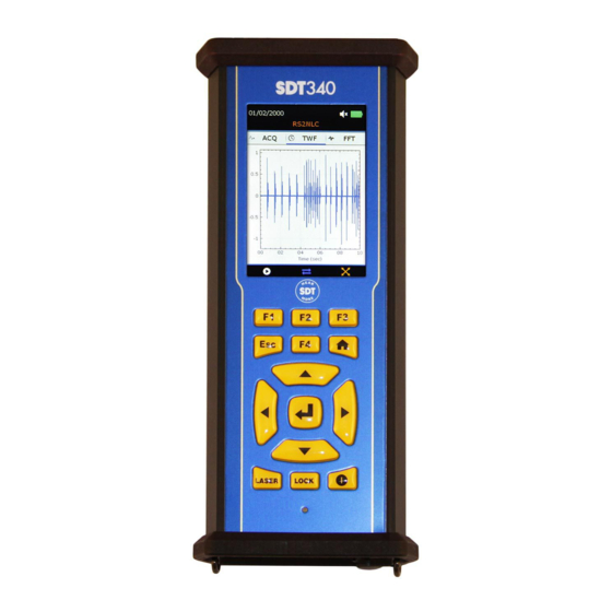
SDT340 User Manual
TANKTEST MODE
USER MANUAL
2022 – Version 1
© SDT International. All rights reserved. Specifications are subject to change without notice.
SDT International sa-nv • Bd de l'Humanité 415 • B-1190 Brussels (Belgium) • Tel : +32(0)2 332 32 25 • email : info@sdtultrasound.com
SDT North America • 7677 County Road 2 • Cobourg ON K9A 0X4 (Canada) • Phone : 1-800-667-5325 | 1-905-377-1313 • email : hearmore@sdtultrasound.com
www.sdtultrasound.com
Advertisement
Table of Contents

Related Manuals for SDT SDT340


Summary of Contents for SDT SDT340
- Page 1 SDT International sa-nv • Bd de l’Humanité 415 • B-1190 Brussels (Belgium) • Tel : +32(0)2 332 32 25 • email : info@sdtultrasound.com SDT North America • 7677 County Road 2 • Cobourg ON K9A 0X4 (Canada) • Phone : 1-800-667-5325 | 1-905-377-1313 • email : hearmore@sdtultrasound.com...
-
Page 2: Table Of Contents
DC.R340TT.MAN.001—01—User Manual SDT340TANKTEST EN Table of Contents Table of Contents ............................ 2 Safety .............................. 3 Caution ............................3 CE compliance ..........................4 Introduction ............................ 5 Field of application ......................... 5 Unpacking ............................7 Battery ............................. 7 Controls and connections ....................... 9 8.1. -
Page 3: Safety
Lifetime Warranty. Contact SDT Ultrasound Solutions or an SDT Authorized Service Provider. The permissible ambient temperature range for the operation of the SDT340 is -15 °C to +60 °C (5 °F to 140 °F). Relative humidity must be less than 90%, non-condensing. -
Page 4: Ce Compliance
The audio output paired with the Peltor headsets supplied by SDT, having the references FUHDPH-1 and FUHDPH-2 delivers a maximum sound pressure level of 79 dB. SDT makes an additional safety guarantee to our users. When connecting a sensor, or selecting/changing sensors, SDT instruments self-adjust the volume to a default, maximum sound pressure level of 58 dB typical. -
Page 5: Introduction
DC.R340TT.MAN.001—01—User Manual SDT340TANKTEST EN 4. Introduction The SDT340 TankTest is a control and diagnostic tool for underground storage tanks. The SDT340 includes the following features: • • Ultrasound and vibration measurements 256 kHz sample rate, reduced to 32 kHz by... - Page 6 DC.R340TT.MAN.001—01—User Manual SDT340TANKTEST EN The determination of the vacuum and the admissible product height for acoustic controls, on tanks meeting the construction standards stated above, is imposed, independently of SDT International. Nominal Construction External Nominal Permissible Maximum capacity in standards...
-
Page 7: Unpacking
SDT International cannot be held responsible, in case of disregard of the test procedures 6. Unpacking The items that follow are included in your purchase of the SDT340 TankTest kit. Unpack and inspect them. •... - Page 8 DC.R340TT.MAN.001—01—User Manual SDT340TANKTEST EN ❷ ❸ ❹ ❷ Force battery charge ❶ ❶ Power supply connector ❷ Force battery charge location ❸ Battery pack placed on the docking station ❹ Docking Station LED Based on XP Power, Model ACM24 series (you may find other AC/DC power supply: references/brand depending on your order date.
-
Page 9: Controls And Connections
Disconnect and then reconnect the power supply from the main to reset the docking station. The SDT340 autonomy is typically 8 hours for a fully charged battery pack and the recharge time is about 7 hours. 8. Controls and connections ❶... -
Page 10: Power On
Plug & Unplug a Sensor SDT 340 has 2 input ports with 7-pole LEMO connectors for external sensors. The channel with the red collar is dedicated to the sensor to be immersed in the liquid as the black one is reserved for the airborne sensor. -
Page 11: Home Screen
DC.R340TT.MAN.001—01—User Manual SDT340TANKTEST EN 9. Home screen Connect the sensors to the SDT340 to display the icons associated with the TankTest mode ❶ Tree Structure Data Collection Mode ❾ ❿ ❻ ❷ General Settings ❽ ❼ ❶ ❷ ❸ ❸... -
Page 12: Tree Structure Mode
DC.R340TT.MAN.001—01—User Manual SDT340TANKTEST EN 10. Tree Structure Mode In this mode, the SDT340 TankTest shows the tests already performed and the status of the database. Access the mode from the home screen, by clicking on the icon and then pressing Enter. -
Page 13: Guided Tanktest Mode
DC.R340TT.MAN.001—01—User Manual SDT340TANKTEST EN ▪ TTB2(Ht-32k): with the black sensor, in airborne phase o Test: Vacuum measurements ▪ TTR2(RW-32k): with the red sensor, in liquid phase ▪ TTB2(Ht-32k): with the black sensor, in airborne phase The example below, applied to the "Tank1" memory location, describes the tree structure mode readback options. - Page 14 Enter. The first screen reminds: 1. That the SDT340 equipment and its accessories are not designed to be used in ATEX zones. 2. That the TankTest sensors must not be disconnected during a guided test, otherwise the measurements will be lost. Disconnecting sensors during a non-finalized test will cause the mode to be closed.
- Page 15 DC.R340TT.MAN.001—01—User Manual SDT340TANKTEST EN ❶ Access to the guided TankTest mode ❷ Usage reminders ❶ ❸ User choice: Leak simulator. In practice, the leak simulator is used at the end of the test as a functional test of the equipment, in the presence of a calibrated flow.
- Page 16 DC.R340TT.MAN.001—01—User Manual SDT340TANKTEST EN ❶ Node or memory location occupied ❷ Node or memory location selected ❸ Remaining nodes or memory locations ❹ Go to the next step with the F3 key. Confirm the selected choice with ENTER ❶ ❷ ❸...
- Page 17 DC.R340TT.MAN.001—01—User Manual SDT340TANKTEST EN ❶ Field associated with the determination of the reference levels (REF), before application of the vacuum. Not configurable ❶ ❷ Field associated with the measurements, in vacuum (TEST) Configurable by the operator, between 20 seconds and 10 minutes, 120 seconds by default Refer to your country's regulations ❸...
- Page 18 DC.R340TT.MAN.001—01—User Manual SDT340TANKTEST EN ❶ Diameter of the tank, in mm ❷ Height of the liquid, before the test ❸ Height of water, before the test ❹ Go to the next screen with F3 ❶ ❷ ❸ ❹ Before proceeding with the installation of the sensors, the following points should be noted: The sensors should be handled with care, especially on their sensitive side.
- Page 19 DC.R340TT.MAN.001—01—User Manual SDT340TANKTEST EN ❶ Place the position of the sensors in the tank Tightening must be done MANUALLY at the cable glands located on the Camlock. ❷ Return to the previous step with F2 ❸ Go to the next step with F3 ❶...
- Page 20 DC.R340TT.MAN.001—01—User Manual SDT340TANKTEST EN ❶ Isolate the installation to be controlled Follow the instructions on the screen - Seal the "open" parts of the installation with plugs - Install the leak simulator between the ❶ camlock and the tank, if selected in step 1 and close its valve - Lock the Camlock and the leakage simulator to the system...
- Page 21 DC.R340TT.MAN.001—01—User Manual SDT340TANKTEST EN The test equipment is now installed. The following screen details the predefined settings on the SDT340 TankTest device ❶ Sensor amplification is set to maximum ❷ The sound level of the helmet is preset to 30%, for safety. The operator will be able to adjust this level afterwards ❶...
- Page 22 DC.R340TT.MAN.001—01—User Manual SDT340TANKTEST EN as well as in the TankTest Reporter software used for the edition of the reports, after having exported the data on your computer. ❶ Identification of the memory location (Tank4/Ref) as well as the sensor considered (TTB2•= airborne phase) ❷...
- Page 23 DC.R340TT.MAN.001—01—User Manual SDT340TANKTEST EN ❶ Example of the taking of the reference on the TTBR2 sensor • ❷ Summary screen. The measurement is frozen on the screen after an acquisition. ❶ Press the Enter key to validate the acquisition ignore present ❷...
- Page 24 DC.R340TT.MAN.001—01—User Manual SDT340TANKTEST EN ❶ Continuity test Open the valve(s) and make sure that a small vacuum can be applied to the system and then release this vacuum from one end. Check that the disturbances are recreated by the device. If you encounter problems at this stage, ❶...
- Page 25 DC.R340TT.MAN.001—01—User Manual SDT340TANKTEST EN ❶ Enter the value of the stabilized vacuum. Use the directional arrows "up" and "down" on the device Turn on the vacuum pump with the valve open. When the vacuum reaches the target value, close the valve and stop the vacuum pump.
- Page 26 DC.R340TT.MAN.001—01—User Manual SDT340TANKTEST EN ❶ Identification of the memory location (Test) as well as the sensor considered (TTB2 •= airborne phase) The operator wears the headset, in order to detect possible anomalies by listening. ❶ In case of rapid loss of vacuum, check the continuity of the installation.
- Page 27 If you have taken both measurements at low pressure, press F3 to switch to the next screen. The leak simulator is proposed by SDT for functional testing purposes, in accordance with regulatory constraints. This tool allows to attest the functioning of the Note: measurement chain, the day of the intervention.
- Page 28 DC.R340TT.MAN.001—01—User Manual SDT340TANKTEST EN ❶ Read the vacuum value on the pressure gauge. Use the "up" and "down" arrows to make your choice. ❷ Return to the "measurement" screens with the F1 key, especially if the vacuum value has dropped by more than 5% from the stabilized value ❶...
- Page 29 DC.R340TT.MAN.001—01—User Manual SDT340TANKTEST EN ❶ Instructions for the end of the test ❷ Return to the previous screen ❸ Go to the next screen with the F3 key ❶ ❸ ❷ For all purposes, the operator is asked to measure and then fill in the following information: Diameter of the tank Height of the liquid Height of water...
-
Page 30: Measurement In Free Mode Tab
DC.R340TT.MAN.001—01—User Manual SDT340TANKTEST EN ❶ Final screen of the guided mode Press Enter to store the entire tightness test. A message will confirm the saving. The operator can then revisit his measurements from the "tree structure" mode. ❶ ❷ Return to the previous screen with the F1 key ❷... -
Page 31: General Settings
DC.R340TT.MAN.001—01—User Manual SDT340TANKTEST EN Outside the guided mode, saving of signals is not allowed. The operator can perform various functional tests from this mode, but without being able to save them in the device's memory. The screen below is common to both TankTest sensors and the flexible sensor: ❶... -
Page 32: System Info
DC.R340TT.MAN.001—01—User Manual SDT340TANKTEST EN ❶ System info setting ❷ Language setting ❸ Bluetooth setting ① ❹ Date and hour setting ❷ ❺ Brightness setting ❸ ❻ Auto power down setting ❼ Metric imperial setting ❹ ❽ Network setting ❺ ❾ Theme setting ❻... -
Page 33: Device Info
DC.R340TT.MAN.001—01—User Manual SDT340TANKTEST EN 13.1.1. Device info ❶ Equipment number ❷ PCB Serial ID number ❸ PCB number ❶ ❹ PCB issue number ❷ ❺ Batch number ❻ Batch manufactured month ❸ ❼ Batch manufactured year ❹ ❺ ❻ ❼ With the Up and Down navigation keys highlight the desired settings and confirm your choice with Enter. -
Page 34: Battery Info
DC.R340TT.MAN.001—01—User Manual SDT340TANKTEST EN 13.1.4. Battery info ❶ Current capacity (in %) ❷ Battery serial ID ❸ Battery serial number ❶ ❹ nominal capacity (in mAH) ❷ ❺ Number of charge/discharge cycles ❻ Battery temperature (in °C or °F) ❸ ❼... -
Page 35: Software Info
DC.R340TT.MAN.001—01—User Manual SDT340TANKTEST EN 13.1.6. Software info ❶ Firmware version ❷ Kernel version. ❸ FPGA version ❶ ❹ UBoot version ❷ ❺ Library version ❸ ❻ Build version ❼ Bluetooth audio version ❹ ❺ ❻ ❼ With the Up and Down navigation keys highlight the desired settings and confirm your choice with Enter. -
Page 36: Manufacturer Info
DC.R340TT.MAN.001—01—User Manual SDT340TANKTEST EN 13.1.9. Manufacturer info 13.2. Language With the Up and Down navigation keys highlight the desired settings and confirm your choice with Enter. Press the button ESC to display the previous screen. 36/44... -
Page 37: Bluetooth
Press ❷ to enable the Bluetooth headset module. Switch on the headset. The headset must emit a blue flashing light. Press F3 to pair ❻ the SDT340 with the headset. 13.4. Date and time format ❶ Locale date and time ❷... -
Page 38: Brightness
❷ ❸ ❹ Once you connect the SDT340 to a computer, the network settings information will be automatically listed on the SDT340 screen if automatic has been selected and if not, enter the settings information must be selected manually. 38/44... -
Page 39: Theme
Enter. 14. Using the TankTest Reporter software Connect the SDT340 to a computer on which SDT TankTest Reporter is installed, using the USB cable provided. Start the software, supposedly up to date, with an activated license and an internet connection. -
Page 40: Cleaning The Device Memory
Please note that the data remains in the device, as long as the user does not voluntarily decide to delete it. However, SDT recommends that the internal memory of the unit be regularly erased, limited to 50 nodes/tanks. 14.2. -
Page 41: Updates
DC.R340TT.MAN.001—01—User Manual SDT340TANKTEST EN After a few moments, the memory of the SDT340 device is completely restored. The data contained in the device has been permanently deleted. The tree structure mode now contains only empty memory locations. 14.3. Updates From the main screen, use the "Update SDT device" option to ensure you are using the latest firmware version. -
Page 42: Recommended Calibration Intervals
SDT recommends this simple procedure, which can solve potential problems encountered by users. 15. Recommended calibration intervals SDT recommends annual recalibration of SDT instruments and annual verification of sensors to benefit from its limited lifetime warranty. This periodicity is coherent with the observed long-term stability of SDT electronic equipment’s. -
Page 43: Warranty
SDT340 unit or its accessories, bodily harm, loss of time, financial or material loss or any other indirect or consequential loss arising out of the use, or inability to use this product, even when it has been warned of possible damages. -
Page 44: Copyright
DC.R340TT.MAN.001—01—User Manual SDT340TANKTEST EN SDT International will transfer the rest of the apparatus to a local company that will recycle it in accordance with EU "WEEE" Directive and Belgian laws. 19. Copyright © 2022 SDT International n.v. s.a. All rights reserved.
Need help?
Do you have a question about the SDT340 and is the answer not in the manual?
Questions and answers