Table of Contents
Advertisement
Quick Links
Advertisement
Table of Contents

Related Manuals for Eastwood B100


Summary of Contents for Eastwood B100
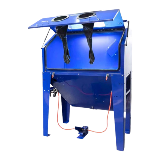
- Page 1 Item #21301 ABRASIVE MEDIA BLAST CABINET – B100 INSTRUCTIONS...
-
Page 2: Specifications
• For best results, a compressor capable of providing a minimum of 12 CFM @ 90 PSI is required. Less available CFM will not provide sufficient force to allow the Blaster to adequately remove rust and or paint. • The use of Eastwood blast media is strongly recommended for proper operation. Use care to avoid using excessive grit size which can block the Nozzle. SPECIFICATIONS •... -
Page 3: Safety Information
HEALTH AND INJURY HAZARDS! • The Eastwood Abrasive Media Blast Cabinet consists of large, heavy metal components which can cause potentially serious injuries if allowed to drop. Avoid pinching hands while handling parts during assembly. The assistance of a helper during assembly is necessary. - Page 4 ASSEMBLY FIG. 1 The Eastwood Abrasive Media Blast Cabinet consists of large, heavy metal components which can cause potentially serious injuries if allowed to drop. Avoid pinching hands while handling parts during assembly. The assis- tance of a helper during assembly is neces- sary.
- Page 5 • Insert 4 M6 x 12 mm Screws from the outside and add 4 Nuts (FIG 5). • Repeat for front and rear legs at opposite side. Holes FIG. 4 FIG. 5 To order parts and supplies: 800.343.9353 >> eastwood.com...
- Page 6 FIG. 7 • Align all holes in Legs and Cabinet and add an additional 4 sets of Screws and Nuts per side. Tighten all hardware securely (FIGS 7 & 8). FIG. 8 Eastwood Technical Assistance: 800.343.9353 >> tech@eastwood.com...
- Page 7 • Align contact pins at the end of Fluorescent Tubes with the spring-loaded lamp receptacles (FIGS 9 & 10), push in, and allow pins at opposite end of Tube to fit into opposite receptacle. FIG. 10 To order parts and supplies: 800.343.9353 >> eastwood.com...
- Page 8 6 holes in the cabinet top (FIG 12). • Add the 6 previously removed Light Fixture Screws. NOTE: No nuts are required as these are pre-attached weld-nuts (FIG 13). FIG. 12 FIG. 13 Eastwood Technical Assistance: 800.343.9353 >> tech@eastwood.com...
- Page 9 (FIG 14). • Slip the end of the Orange Air Supply Hose over the inner nipple of the 90° Bulkhead Fitting and secure it with the Compression Ring (FIG 15). FIG. 15 To order parts and supplies: 800.343.9353 >> eastwood.com...
- Page 10 • Set the Perforated Cabinet Floor (H) (with angled cut off corner toward right front of cabinet) and allow the edges to rest on the internal Cabinet support flanges (FIGS 16 & 17). FIG. 17 Eastwood Technical Assistance: 800.343.9353 >> tech@eastwood.com...
- Page 11 Nuts (FIG 18). • Slip the end of the Orange Air Supply Hose over the outer nipple of the 90° Bulkhead Fitting and secure it with the Compression Ring (FIG 19). FIG. 19 To order parts and supplies: 800.343.9353 >> eastwood.com...
- Page 12 • Connect the Plug on the power supply cord with the female Receptacle on the cord attached to the Light Fixture (FIG 22). • The Eastwood Abrasive Media Blast Cabinet is now fully assembled and ready for set-up. FIG. 21 FIG.
-
Page 13: Operation
SET-UP BLAST CABINET FOR USE FIG. 23 • Add Eastwood approved Blast Media. Fill to within 10” of the Perforated Floor support flanges. DO NOT OVERFILL. Overfilling will degrade performance. DO NOT USE SAND IN THIS BLAST CABINET! NOTE: for best results and to avoid nozzle clogging, do not use media larger than 60 grit particle size. -
Page 14: Maintenance
- Loosen Air Jet Lock Nut and turn Air Jet out of rear of Gun. - Install new Air Jet, then tighten Air Jet Lock Nut. - Reinstall Air Inlet Fittings. - The Blast gun is now once again ready for use. Eastwood Technical Assistance: 800.343.9353 >> tech@eastwood.com... - Page 15 - When draining stops, clear excess media from seal area of the Drain Panel, close and latch the Clasp securely. - Add Eastwood approved Blast Media. Fill to within 10” of the Perforated Floor support flanges. DO NOT OVERFILL. Overfilling will degrade performance.
-
Page 16: Vacuum Maintenance
- When done, replace Filter and secure it with the Filter Retaining Washer and Wingnut. - Replace the Motor & Filter assembly back into the Housing and latch the Clasps securely. - Reconnect the Power Supply Cord. Eastwood Technical Assistance: 800.343.9353 >> tech@eastwood.com... - Page 17 Assembled – Included with “A” Assembled – Included with “A” Assembled “G” To order parts and supplies: 800.343.9353 >> eastwood.com...
- Page 18 NOTES Eastwood Technical Assistance: 800.343.9353 >> tech@eastwood.com...
-
Page 19: Troubleshooting
Empty Filter Housing per procedure in Maintenance Section. Becomes Filter Housing is Full of Dust Obstructed Clean Filter per procedure in Maintenance Section. Plastic Peel-Off Shield is Worn Clean inside of window and replace Peel-off shield. To order parts and supplies: 800.343.9353 >> eastwood.com... -
Page 20: Additional Items
If you have any questions about the use of this product, please contact The Eastwood Technical Assistance Service Department: 800.343.9353 >> email: tech@eastwood.com PDF version of this manual is available at eastwood.com The Eastwood Company 263 Shoemaker Road, Pottstown, PA 19464, USA 800.343.9353 eastwood.com © Copyright 2019 Easthill Group, Inc. 2/19...
Need help?
Do you have a question about the B100 and is the answer not in the manual?
Questions and answers