
Subscribe to Our Youtube Channel
Related Manuals for OSS Centauri OSS-EXS-C4B


Summary of Contents for OSS Centauri OSS-EXS-C4B
- Page 1 Centauri Storage Expansion Unit OSS-EXS-C4B User Manual SKU: OSS-EXS-C4B www.onestopsystems.com...
-
Page 2: Table Of Contents
Plug-in the power cords to the storage expansion unit....19 3.4.2 Plug in power cords to a PDU Power Strip ....... 20 Install OSS-518 Host Adapter Card .......... 22 Connect LINK Cables ............23 3.6.1 Connect SFF-8643 cables to storage expansion unit ...... 23 3.6.2... - Page 3 5.2.1 Drive & Slot Hierarchy – Linux ......... 39 Windows OS: How to Check the NVME Drives ........44 Windows OS: How to Check OSS Storage Expansion unit ......46 5.4.1 Drive & Slot Hierarchy – Windows OS ........49 Troubleshooting ..............
- Page 4 Change IP address to Static or DHCP ........73 Reinstall or reflash IPMI ..........73 Contacting Technical Support ........... 74 Returning Merchandise to One Stop Systems ........74 Shipping / transporting the card ..........75 APPENDIX A Compliance ............76 OSS-EXS-C48...
-
Page 5: Preface
Disclaimer: We have attempted to identify most situations that may pose a danger, warning, or caution condition in this manual. However, One Stop Systems does not claim to have covered all situations that might require the use of a Caution, Warning, or Danger indicator. OSS-EXS-C48... -
Page 6: Safety Instructions
As you pull connectors apart, keep them evenly aligned to avoid bending any connector pins. Also, before connecting a cable, make sure both connectors are correctly oriented and aligned. OSS-EXS-C48... -
Page 7: Protecting Against Electrostatic Discharge
Manage all sensitive components at an ESD workstation. If possible, use anti-static floor pads and workbench pads. Handle components and boards with care. Do not touch the components or contacts on a board. Hold a board by its edges or by its metal mounting bracket. OSS-EXS-C48... -
Page 8: General Specification
Korea KN22, Class A; KN24 Russia/GOST ME01, IEC-60950-1, GOST R 51318.22, GOST R 51318.24, GOST R 51317.3.2, GOST R 51317.3.3 TUV-GS (EN60950-1 /IEC60950-1,EK1-ITB2000) Compliance RoHS 3, WEEE Operating Systems Supports servers and initiators running Microsoft Windows, Windows Server, and Linux OSS-EXS-C48... -
Page 9: Product Information
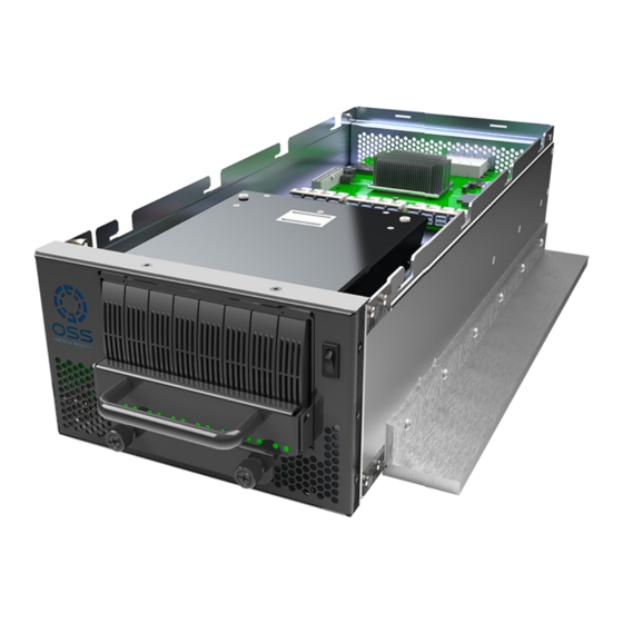
PCIe 4.0 x16 SFF-8643 Host Uplink • BMC and fan control Built as a modular storage expansion to the OSS 3U SDS, Centauri can store up to 256 TB in its 8-drive canister. • These canisters allow for tool-less bulk or individual drive removal and can be hot-swapped for ease of use in fast-paced environments. -
Page 10: Chassis Dimension
One Stop Systems Chassis Dimension Block Diagram OSS-EXS-C48... -
Page 11: Power
Ext Typ Power Power Centauri Part Type Power Type Power Max (Watts) (Watts) NVME SDDs PCIe Card Misc. 565, 565, 566, 567 San Ace or Delta Fans 40x40x28 Power consumed in CRPS (assume 90% CRPS Supply efficiency) Total Power (Watts) OSS-EXS-C48... -
Page 12: Oss-528 Board Leds
One Stop Systems OSS-528 Board LEDs Normal Visible 528 LED Color Notes State (not visible outside Chassis) PEX Fatal Error 528 Board Only Green PEX Heartbeat LED Flashing 528 Board Only Green PCIe Reset Asserted 528 Board Only FPGA CRC Error... -
Page 13: Oss-528 Fpga Dipswitch Settings
One Stop Systems OSS-528 FPGA Dipswitch Settings OSS-528 Shipping DIP Switch Setting Signal Function Setting Position Switch Low: BSw SW1 Pos 1 GPSW1 Flash Select: High: SSw GPSW1: High GPSW2: Low SW1 Pos 2 GPSW2 Low (ON) SW1 Pos 3... -
Page 14: Ssd Slot Vs. Port Mapping
Each SSD slot in the drivepack is assigned with a hardcoded PCIe port. SSD Slot PCIe Port SSD1 Port 28 SSD2 Port 30 SSD3 Port 24 SSD4 Port 26 SSD5 Port 20 SSD6 Port 22 SSD7 Port 16 SSD8 Port 18 SFF-8644 PCIe Port Port 0 OSS-EXS-C48... -
Page 15: Ssd Slot Vs. Nvme# Assignment
2.10 SSD Slot vs. nvme# Assignment Applicable only to Centauri units with an 8-drive configuration (all 8 SSD slots populated with NVME drives). SSD Slot NVME# SSD1 nvme6n1 SSD2 nvme7n1 SSD3 nvme4n1 SSD4 nvme5n1 SSD5 nvme2n1 SSD6 nvme3n1 SSD7 nvme0n1 SSD8 nvme1n1 OSS-EXS-C48... -
Page 16: Centauri Overview
One Stop Systems 2.11 Centauri Overview OSS-EXS-C48... - Page 17 One Stop Systems OSS-EXS-C48...
-
Page 18: Setting Up
One Stop Systems Setting Up Installation Overview • Remove Top cover • Verify SW1 dipswitch setting on OSS-528 board • Plug in power cords • Install OSS Host adapter card • Connect LINK Cables • Power UP the Centauri •... -
Page 19: Verify Sw1 Dipswitch Setting
Gently pull the top cover then lift it up. Verify SW1 Dipswitch Setting Check the SW1 dipswitch settings on the OSS-528 BOARD. Make sure the switches are set correctly. Refer to the photos below for the correct settings. Connect Power Cords 3.4.1 Plug-in the power cords to the storage expansion unit. -
Page 20: Plug In Power Cords To A Pdu Power Strip
It is highly recommended to use PDU with surge protection. Photo below is an example of PDU power strip. Turn ON the PDU power strip, upon switching ON, the LEDS on the power supply will illuminate from solid amber to blinking green. OSS-EXS-C48... - Page 21 One Stop Systems In the storage expansion unit, the CR2 RED LED on the “PDB-Power Distribution Board” will illuminate as solid RED (standby mode). 3.3AUX on the OSS-528 board will illuminate as solid green, see photos below. OSS-EXS-C48...
-
Page 22: Install Oss-518 Host Adapter Card
Plug in the OSS host card in the computer’s motherboard, use available x16 PCIe slot Gen4. Secure the card. Photo below shows the position of the OSS host card in the server. OSS-EXS-C48... -
Page 23: Connect Link Cables
Avoid forcing the link cables during installation. If the cable is not sliding in properly, do not force it in as this can damage the connector in the OSS-528 board. Check the cable-end connector for bent or protruding metal piece. -
Page 24: Connect Sff-8643 Cables To Host Card
One Stop Systems 3.6.2 Connect SFF-8643 cables to Host card Connect the other end of the cables to the OSS host card. • Start connecting the 1 cable to Primary port 0, located on the TOP side. cable to Port 1 3rd cable to Port 2 cable to Port 3 on the BOTTOM side. -
Page 25: Turn On The Storage Expansion Unit
One Stop Systems Turn ON the Storage Expansion Unit Press the front switch to ON position. Upon powering ON the storage expansion unit, the following LEDS on the OSS-528 board will illuminate. 1.8VA-------->D26: Solid green 0.9V--------->D25: Solid green PWGD------->D1: Solid green GPI----------->CR2: Blinking green... -
Page 26: Turn On The Server
The following LEDs will illuminate on the Power Distribution Board. PG----------->Solin green CR2--------------> Solid green With the unit fully powered ON, the OSS LOGO LED will illuminate as solid blue and the power supply LEDs will illuminate as solid green. See photos below. Front LED Logo----------->Blue Power Supply------------->Solid green... - Page 27 One Stop Systems Upon powering UP the host computer the LINK LED on the OSS-528 board will illuminate as solid green. D5-----Link LED is Solid green. If the LINK LED is not coming ON, this indicates that there is NO connection between the computer and a storage expansion device.
- Page 28 (CARD EDGE)--------------->D11: solid green. • This indicates a solid signal between the PCIe host card and the CPU. PWR—------------------------------>D10: Blinking green (7 times interval). LED0------------------------------>D2: solid green LED1------------------------------>D4: solid green LED2------------------------------>D6: solid green LED3------------------------------>D8: solid green AUX----------------------------->D9: solid green OSS-EXS-C48...
-
Page 29: Drive Installation
Grab the Drive pack front handle and gently pull the Drive pack away from the enclosure. Set the Drive pack on a solid surface. Remove the mounting screw on each side. Dismount the handle to access the drive trays. OSS-EXS-C48... -
Page 30: Mount The Drives
Place the Drive pack on a solid surface in a vertical position. When installing 8 drives, start installing the drive tray from the far-end right drive slot. This would give you visibility on the board slot during the drive tray installation. OSS-EXS-C48... - Page 31 Make sure the drive connector is fully seated in the drive slot, see photo below Push the drive tray into the hard drive bay as illustrated below, until the drive tray clicks into the locked position. Using the thumb, push against the lower part of the hard drive handle. OSS-EXS-C48...
-
Page 32: Reinstall The Drive Pack
If link cables are not connected, reconnect the cables. • Start connecting the cable from left to right on the storage expansion unit. • Plugin the other cable to the host card in the computer. Start connecting cable from top to bottom. OSS-EXS-C48... -
Page 33: Power Up The System
One Stop Systems Power UP the System Flip the front power switch on the Centauri unit. Eight additional LEDs on the OSS-528 board will instantly illuminate as solid green, see photos below. Eight Drive LEDs located on the front will illuminate as solid AMBER. -
Page 34: The Unit Is Ready
On WINDOWS OS: Launch “Windows Disk Management” to check if all 8 drives are detected and to reinitialize each drive. • On Linux: You need to install nvme application. Run” nvme list” command on the terminal windows to list all the drives. For more information go to “Post Installation” section. OSS-EXS-C48... -
Page 35: Post Installation
One Stop Systems Post Installation Linux: How to Check OSS Storage Expansion unit To check the OSS devices, type lspci -vvv | grep c010 on Linux terminal windows. Run the command as root user. • The output below shows 16 c010 devices. It indicates that the CPU is detecting both OSS-518 host adapter cards and the OSS-528 board in the storage expansion unit. - Page 36 One Stop Systems To view the OSS devices in a hierarchy or tree-like structure, type lspci -vvtt | grep -i 'Broadcom' on Linux terminal window. See output below. • Run the command as root user. To check and view the link speed and link width of the OSS device.
- Page 37 One Stop Systems To check the link speed and link width of the OSS Broadcom device, use the following command. • lspci -vvv -s 94:00.0 | grep 'LnkSta\|LnkCap' • Replace the PCI BUS Number 94:00.00 with the PCI BUS number assigned to your device (from your system).
-
Page 38: Linux: How To Check The Nvme Drives
#nvme -list, output below shows 9 NVME drives are detected. Out of the 9 drives, the eight are the nvme drives in the OSS Drive pack. The 9 drive is the primary boot device in the computer. To identify the primary or main nvme bootable device from the list (above), use the command df -ht | grep /$. -
Page 39: Drive & Slot Hierarchy - Linux
OS is running. Using lspci -vvtt command on the terminal window will display the nvme drive slot hierarchy order. One NVME drive is ejected / removed from slot#1 in the Drive pack. • Photo below shows the empty spot that was occupied by the NVME drive. OSS-EXS-C48... - Page 40 Photo below shows the empty spot that was occupied by the NVME drive. One NVME drive is ejected / removed from slot#3 in the Drive pack. • Photo below shows the empty spot that was occupied by the NVME drive. OSS-EXS-C48...
- Page 41 Photo below shows the empty spot that was occupied by the NVME drive. One NVME drive is ejected / removed from slot#5 in the Drive pack. • Photo below shows the empty spot that was occupied by the NVME drive. OSS-EXS-C48...
- Page 42 Photo below shows the empty spot that was occupied by the NVME drive. One NVME drive is ejected / removed from slot#8 in the Drive pack. • Photo below shows the empty spot that was occupied by the NVME drive. OSS-EXS-C48...
- Page 43 On the terminal window, type lspci -vvv -s 8c:00.0 | grep 'LnkSta\|LnkCap' It will display the “Link Speed: and Link Width.” The drive slot runs at Gen4 (x16GT/s speed), and the Link Width is @ x2, see output below. OSS-EXS-C48...
-
Page 44: Windows Os: How To Check The Nvme Drives
To check the NVME drives on Windows, there are multiple ways to do it. You can use the Windows Disk Management or the Windows Device Manager. Using Windows Disk Management: From the Windows desktop, right click on the Windows LOGO and select Disk Management. • Screenshot below shows 8 NVME drives detected. OSS-EXS-C48... - Page 45 From the Windows desktop, right click on the Windows LOGO and select Device Manager. • From the top menu, select VIEW, then select “Device by Type.” • Select Disk drives and expand or collapse the “arrow sign” or the “plus sign.” • Screenshot below shows 8 NVME drives detected. OSS-EXS-C48...
-
Page 46: Windows Os: How To Check Oss Storage Expansion Unit
One Stop Systems Windows OS: How to Check OSS Storage Expansion unit Using Windows Device Manager – Devices by Connection: 1. Start Device Manager 2. From the top menu, click View; from the list select "Devices by connection". 3. Scroll down, expand all the arrow ">" signs or plus "+" signs 4. - Page 47 One Stop Systems The PCI Express Downstream Switch Port encircled below indicates that the “storage- expansion” unit is detected. Screenshot below shows the NVME drive controllers. OSS-EXS-C48...
- Page 48 One Stop Systems Screenshot below shows all 8 NVME drives detected and no yellow exclamation mark symbol. These 8 drives are installed in the Drive pack. OSS-EXS-C48...
-
Page 49: Drive & Slot Hierarchy - Windows Os
One Stop Systems 5.4.1 Drive & Slot Hierarchy – Windows OS The screenshot below shows the drive slot hierarchy in Windows Device Manager. OSS-EXS-C48... - Page 50 One Stop Systems The screenshot below shows 8 NVME drives hierarchy in Windows Device Manager. OSS-EXS-C48...
-
Page 51: Troubleshooting
2. Check Drive LINK LEDs a. Remove the top cover, check the drive LINK LEDs on the OSS-528 and see which one is not coming UP (not illuminated). A fully functional unit will have 8 drive LINK LEDs illuminated as solid green, see photos below. - Page 52 OSS-528 board is not recognizing one of the drives in the Drive pack. 3. Check and reseat the “SFF-8643 to SFF-8643” cable between the OSS-528 and Drive pack, see photos below. If this cable is not fully seated, the NVME drives will not be recognized.
-
Page 53: Oss-528 Drive Link Leds
One Stop Systems OSS-528 Drive LINK LEDs There are 8 Drive LINK LEDs on the OSS-528 boards. • These LED indicators will serve as a hardware tool for diagnosing and troubleshooting NVME drive issues (i.e., not detected). • 8 Drive LEDs on the OSS-528 boards, see photo below... - Page 54 One Stop Systems As shown from the diagram below, each LED on the OSS-528 board is mapped to individual drive slot in the drive pack. • When drive is present in drive Slot#8, D9 LED will illuminate. OFF when drive slot is empty.
- Page 55 One Stop Systems The diagram below is the connection between the SFF-8643 connector on the OSS-528 board and OSS-565 board. The sff-8643 connector on the OSS-528 board is tied to the drive LED indicator. The SFF-8643 connector on the OSS-565 board is tied to the drive slots in the Drive pack.
- Page 56 One Stop Systems • When cable #1 is detached between SSD3 & J2-A. LEDs D9 & D8 will be OFF, no drives will be detected in drive slots #8 and #7. OSS-EXS-C48...
- Page 57 One Stop Systems • When cable #2 is detached between SSD2 and J2-B. LEDs D9, D8, D7 and D6 LEDs will be OFF, no drives will be detected in drives slots #8, #7, #6 and #5. OSS-EXS-C48...
- Page 58 One Stop Systems • When cable #3 is detached between SSD1 and J1-A. LEDs D18 and D17 will be OFF, no drives will be detected in drive slots #4 and #3. OSS-EXS-C48...
- Page 59 One Stop Systems • When cable #4 is loose or detached between SSDO and J1-B. LEDs D18, D17, D16 and D15 will be OFF, no drives will be detected in slots #4, #3, #2 and 1. OSS-EXS-C48...
-
Page 60: Oss-565 Board: Sff-8643 Connectors
One Stop Systems OSS-565 board: SFF-8643 Connectors There are six SFF-8643 connectors on the OSS-565 board. • Only four SFF-8643 connectors are needed for NVME drives. These connectors are J2-A, J2-B, J1-A and J1-B. • The remaining two connectors J3-A and J3-B are for SATA connection. - Page 61 One Stop Systems SSD3----->connected to J2-A --->mapped to Drive slots #8 and #7. • When cable#1 is detached between J2-A and SSD3, no drives will be detected in drive slots#8 and #7. OSS-EXS-C48...
- Page 62 One Stop Systems SSD2----->connected to J2-B----> mapped to Drive slots #8, #7, #6 and • When cable#2 is detached between J2-B and SSD2, no drives will be detected in drive slots #8, #7, #6 and #5. OSS-EXS-C48...
- Page 63 One Stop Systems SSD1----->connected to J1-A---> mapped to Drive slots #4 and #3. • When cable#3 is detached between J1-A and SSD1, no drives will be detected in drive slots#4 and #3. OSS-EXS-C48...
- Page 64 One Stop Systems SSD0----->connected to J1-B---> mapped to Drive slots #4, #3, #2 and #1. • When cable#4 is detached between J1-B and SSD0, no drives will be detected in drive slots #4, #3, #2 and #1. OSS-EXS-C48...
-
Page 65: Ipmi
(upgrade / update). Please contact sales representative at sales@onestopsystems.com to order the part and request an RMA (Return Material Authorization) to send unit to OSS for an upgrade. The IPMI module is located under the Drive pack. It is visible through the front panel as shown from the photo below. -
Page 66: How To Setup & Access Ipmi
Upon connecting the power, observe the IPMI LED, it will illuminate from solid red to blinking green and to solid green. When the led status is solid green, the IPMI is ready. The IPMI LED is located on the front of the unit, see photos below. OSS-EXS-C48... -
Page 67: Locate Mac Address
Mac address. The photo below shows the location of the label with the Mac address numbers. You need to disassemble and remove the front Drive pack and bracket to access the module. Contact OSS Support prior to disassembling the unit. OSS-EXS-C48... -
Page 68: Discovering The Mac Address / Ip Address
Photo below displays the IP and Mac addresses after running the IP Scanner. • Mac Address 00:18:49:04:F1:b8 and IP address of 10.2.5.2. NOTE: The “nVent,Schroff GmbH” is the vendor / manufacture of the IPMI module. OSS-EXS-C48... -
Page 69: Using Command Prompt Or Windows Terminal
Below photo is an example of Windows PowerShell cmdlet for querying the IP address using the Mac address. • This is just one an example of PowerShell command that you can utilize. There are more commands available that you can use. OSS-EXS-C48... - Page 70 One Stop Systems Linux: Photos below are an example of Linux commands to query the IP address and Mac address. OSS-EXS-C48...
-
Page 71: Start Internet Browser
10.2.5.2. Below photo is the Web interface of the IPMI displaying the status of the following hardware in the storage expansion unit. • Fan status and speed • Drive Backplane temperature • Power supply voltage and temperature OSS-EXS-C48... -
Page 72: How To Login To Ipmi Console
Once you have the Terminal Window or the Command Prompt started: • Type "ssh root@XXX.XXX.X.XXX". Press the ENTER key NOTE: Replace the XXX.XXX.X.XXX with the address assigned to your OSS Storage Expansion unit. • There is no password, press ENTER again. •... -
Page 73: Change Ip Address To Static Or Dhcp
# reboot Reinstall or reflash IPMI Steps below show how to reflash or reload the software onto your IPMI module. You need to SSH first to perform the installation. Run or type the “setup” to initiate the installation. OSS-EXS-C48... -
Page 74: Contacting Technical Support
12) Detailed description of the problem You can also visit our web site at: https://www.onestopsystems.com/ To submit a support ticket or case, use our OSS Online Support portal: https://onestopsystems.com/pages/support-form For a quick response, use the Technical Support and RMA Request Form available in the Support Section of the website. -
Page 75: Shipping / Transporting The Card
Shipping / transporting the card Use appropriate packaging materials. IMPORTANT PCIe cards should be removed (or not to be installed) prior to shipping to avoid or prevent damage, failure to do so, will void the warranty of the unit. OSS-EXS-C48... -
Page 76: Appendix A Compliance
A est conformé à la norme NMB-003 du Canada The product(s) described in this manual complies with all applicable European Union (CE) directives. One Stop Systems will not retest or recertify systems or components that have been reconfigured by customers OSS-EXS-C48... - Page 77 One Stop Systems OSS-EXS-C48...
Need help?
Do you have a question about the Centauri OSS-EXS-C4B and is the answer not in the manual?
Questions and answers