Sign In
Upload
Download
Table of Contents
Contents
Add to my manuals
Delete from my manuals
Share
URL of this page:
HTML Link:
Bookmark this page
Add
Manual will be automatically added to "My Manuals"
Print this page
×
Bookmark added
×
Added to my manuals
Manuals
Brands
Teledyne Manuals
Power Supply
T3PS16081P
User manual
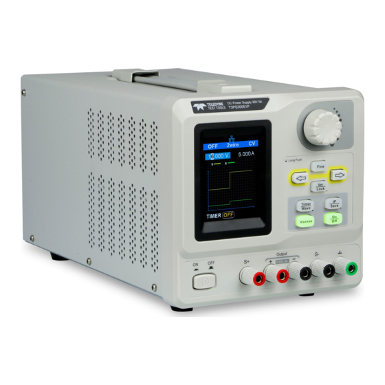
Teledyne T3PS16081P User Manual
Programmable linear dc power supplies
Hide thumbs
1
Table Of Contents
2
3
4
5
6
7
8
9
10
11
12
13
14
15
16
17
18
19
20
21
22
23
24
25
26
27
28
29
30
31
32
33
34
35
36
37
38
39
40
41
42
43
44
45
46
47
48
49
50
51
52
53
54
55
56
57
58
59
60
61
62
63
64
65
page
of
65
Go
/
65
Contents
Table of Contents
Troubleshooting
Bookmarks
Table of Contents
Table of Contents
General Safety Summary
Safety Terms and Symbols
T3PS16081P / 30051P Brief Introduction
Chapter 1 Start Guide
General Inspection
The Front Panel
The Rear Panel
Connect Power
User Interface
Output Inspection
Fuse Replacement
Chapter 2 Control Panel Operation
Output Summary
2-Wire Mode
Remote Sense Mode
Configuration of LAN Interface
Save and Recall
Timer
Waveform Display
Version Information
Lock Key
Upgrade Firmware
Chapter 3 Remote Control
Control Method
Command Format
Command Summary
Command Description
Programming Examples
Chapter 4 Common Troubleshooting
Chapter 5 Service and Support
Contact Teledyne Lecroy
Advertisement
Quick Links
1
Control Method
2
Programming Examples
Download this manual
T3PS16081P / 30051P Programmable
Linear DC Power Supplies
User Manual
Table of
Contents
Previous
Page
Next
Page
1
2
3
4
5
Advertisement
Table of Contents
Need help?
Do you have a question about the T3PS16081P and is the answer not in the manual?
Ask a question
Questions and answers
Related Manuals for Teledyne T3PS16081P
Power Supply Teledyne T3PS12415 User Manual
(37 pages)
Power Supply Teledyne T3PS13206P User Manual
(197 pages)
Power Supply Teledyne T3PSX3200P Series Quick Start Manual
Dc power supply (29 pages)
Power Supply Teledyne T3PS13206 User Manual
(54 pages)
Power Supply Teledyne T3PSX3200 Series Quick Start Manual
(28 pages)
Power Supply Teledyne T3PS3000 Quick Start Manual
Programmable (42 pages)
Power Supply Teledyne T3PS36006 Quick Start Manual
(24 pages)
Power Supply Teledyne T3PS36006 User Manual
(67 pages)
Power Supply Teledyne T3PS30051P User Manual
Programmable linear dc power supplies (65 pages)
Power Supply Teledyne T3PS40381P Programming Manual
Programmable dc power supplies (146 pages)
Power Supply Teledyne LeCroy T3PS Series User Manual
Programmable dc power supply (159 pages)
Power Supply Teledyne T3PS40381P Quick Start Manual
Programmable dc power supplies (32 pages)
Power Supply Teledyne T3PS20051P User Manual
Programmable high precision dc power supplies (217 pages)
Power Supply Teledyne T3PS30721P User Manual
Programmable dc power supplies (156 pages)
Power Supply Teledyne HASTINGS 200 Instruction Manual
(19 pages)
Power Supply Teledyne 3190 Instructions
Retrofitting ac unit to dc (4 pages)
This manual is also suitable for:
T3ps30051p
Table of Contents
Print
Rename the bookmark
Delete bookmark?
Delete from my manuals?
Login
Sign In
OR
Sign in with Facebook
Sign in with Google
Upload manual
Upload from disk
Upload from URL


Need help?
Do you have a question about the T3PS16081P and is the answer not in the manual?
Questions and answers