
Related Manuals for Teledyne T3PS30721P


Summary of Contents for Teledyne T3PS30721P
- Page 1 T 3PS30 721P, T3PS80271P, T 3PS160141P T3PS250041P, T3PS800011P Programmable DC Power Supplies User Manual...
- Page 2 Teledyne LeCroy company. The information in this manual was correct at the time of printing. However, Teledyne LeCroy continues to improve products and reserves the rights to change specification, equipment, and maintenance procedures at any time without notice.
-
Page 3: Table Of Contents
Table of Contents Table of Contents SAFETY INSTRUCTIONS ........... 5 GETTING STARTED ............8 T3PS Series Overview ..........9 Appearance ............... 12 Theory of Operation ..........18 OPERATION ..............32 Set Up ..............33 Basic Operation ............49 Parallel/ Series Operation ........62 CONFIGURATION ............ - Page 4 T3PS Series User Manual T3PS Specifications ..........137 T3PS Dimensions ........... 146 CERTIFICATIONS ............148 EMC Compliance ............ 148 Safety Compliance ..........150 Environmental Compliance ........151 RESTRICTION OF HAZARDOUS SUBSTANCES (RoHS) ..............151 INDEX ................154...
-
Page 5: Safety Instructions
SAFETY INSTRUCTIONS AFETY INSTRUCTIONS This chapter contains important safety instructions that you must follow during operation and storage. Read the following before any operation to ensure your safety and to keep the instrument in the best possible condition. Safety Symbols These safety symbols may appear in this manual or on the instrument. - Page 6 T3PS Series User Manual Do not dispose electronic equipment as unsorted municipal waste. Please use a separate collection facility or contact the supplier from which this instrument was purchased. Safety Guidelines Do not place any heavy object on the T3PS. General ...
- Page 7 SAFETY INSTRUCTIONS Mains supply voltage fluctuations: +/-10 % Overvoltage category: OVC II If the equipment is used in a manner not specified by the manufacturer, the protection provided by the equipment may be impaired. LAN, RS232/RS485 and USB ports are only to ...
- Page 8 T3PS Series Overview ..........9 Series lineup ..................9 Main Features ..................10 Accessories ..................11 T3PS30721P/ T3PS80271P/ T3PS160141P Accessories .. 11 T3PS250041P/ T3PS800011P Accessories ......11 Appearance ............... 12 T3PS Front Panel ................12 Rear Panel ................... 15 Theory of Operation ..........
-
Page 9: Getting Started
The T3PS series consists of 5 models, divided into 2 different model types covering 2 power capacities: Type I (360 Watt) and Type II (720 Watt). Throughout the user manual, T3PS30721P, Note T3PS80271P, T3PS160141P, T3PS250041P or T3PS800011P will refer to any of the T3PS models with a maximum voltage rating of 30V, 80V, 160V, 250V or 800V, respectively. -
Page 10: Main Features
T3PS Series User Manual Main Features High performance/power Performance Power efficient switching type power supply Low impact on load devices Fast transient recovery time of 1ms Fast output response time OVP, OCP and OHP (OTP) protection Features ... -
Page 11: Accessories
GETTING STARTED Accessories Please check the contents before using the T3PS. T3PS30721P/ T3PS80271P/ T3PS160141P Accessories Standard Accessories Description Power cord Output terminal cover Test leads: 1x red, 1x black USB Cable Basic Accessory Kit: M4 terminal screws and washers x2, M8... -
Page 12: Appearance
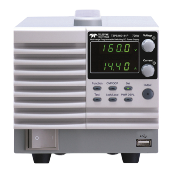
T3PS Series User Manual Appearance T3PS Front Panel 720W: T3PS30721P, T3PS80271P, T3PS160141P Voltage Multi-Range DC Power Supply PSW 30-72 720W Voltage knob Display Current Current knob Cover panel Function OVP/OCP Output Output key Test Lock/Local PWR DSPL Function keys Power switch... - Page 13 GETTING STARTED The Function keys along with the Output key will Function Keys light up when a key is active. The Function key is used to Function configure the power supply. Set the over current or over OVP/OCP voltage protection levels. Sets the current and voltage limits.
- Page 14 T3PS Series User Manual Sets the voltage. Voltage Knob Voltage Sets the current. Current Knob Current Press to turn on the output. The Output Output Output key will light up when the output is active. USB A port for data transfer. Used to turn the power on/off.
-
Page 15: Rear Panel
GETTING STARTED Rear Panel 720W: T3PS30721P, T3PS80271P, T3PS160141P Analog control Sense+ connector terminal USB B port Chassis ground Output Sense- SER.NO. LABEL terminal(+) terminal Output terminal(-) 240V 47 63Hz 1000VA MAX. AC Input 360W: T3PS250041P, T3PS800011P SN.C. S 240V 47 63Hz 500VA MAX. - Page 16 T3PS Series User Manual Standard 26 pin MIL connector Analog Control (OMRON XG4 IDC plug). Connector The analog control connector is used to monitor current and voltage output, machine status (OVP, OCP, OHP (OTP) etc.), and for analog control of the current and voltage output.
- Page 17 The ethernet port is used for remote Ethernet Port control and digital monitoring from a PC. Type I: T3PS250041P/ T3PS800011P Line Voltage Input Type II: T3PS30721P/ T3PS80271P/ T3PS160141P Voltage Input: 100~240 VAC Line frequency: 50Hz/60 Hz (Automatically switchable)
-
Page 18: Theory Of Operation
The operating area of each power supply is determined by the rated output power as well as the voltage and current rating. For example the operating area and rated power output for the T3PS30721P is shown below. Voltage T3PS30721P Operating Area... -
Page 19: Operating Area (Type I)
0 5 10 15 20 25 30 Po… Po… 0 20 40 60 80 0 20 40 60 80 Current (A) Current (A) Cur… Operating Area (Type II) T3PS30721P 0 5 10 15 20 25 30 Po… 0 20 40 60 80 Current (A) Cur…... - Page 20 T3PS Series User Manual T3PS80271P 0 5 10 15 20 25 30 26.6 Po… 0 20 40 60 80 Current (A) Cur… T3PS160141P 14.4 0 5 10 15 20 25 30 Po… 0 20 40 60 80 Current (A) Cur…...
-
Page 21: Cc And Cv Mode
GETTING STARTED CC and CV Mode When the power supply is operating in constant CC and CV mode current mode (CC) a constant current will be Description supplied to the load. When in constant current mode the voltage output can vary, whilst the current remains constant. -
Page 22: Slew Rate
T3PS Series User Manual is equal to I and the voltage output is less than Crossover >R point <R Slew Rate TheT3PS has selectable slew rates for CC and CV Theory mode. This gives the T3PS power supply the ability to limit the current/voltage draw of the power supply. -
Page 23: Bleeder Control
GETTING STARTED Bleeder Control The T3PS DC power supplies employ a bleed Background resistor in parallel with the output terminals. Bleed Load T3PS resistor Bleed resistors are designed to dissipate the power from the power supply filter capacitors when power is turned off and the load is disconnected. -
Page 24: Sink Current Table
T3PS Series User Manual Sink Current Table Sink current (reference value) from an external Background voltage source according to the bleeder circuit setting. T3PS30721P Bleeder ON Bleeder OFF Vout Sink Current (mA) 2.378 0.000 3.613 0.000 3.249 0.004 2.340 0.008 1.487... - Page 25 GETTING STARTED T3PS160141P Bleeder ON Bleeder OFF Vout Sink Current (mA) 0.356 0.004 0.339 0.013 0.303 0.028 0.269 0.048 0.237 0.065 0.216 0.088 0.201 0.119 0.191 0.171 T3PS250041P Bleeder ON Bleeder OFF Vout Sink Current (mA) 0.158 0.031 0.143 0.098 0.129 0.164 0.107...
-
Page 26: Internal Resistance
This allows the power supply to simulate power sources that have internal resistances such as lead acid batteries. Internal Resistance Range Unit Model Internal Resistance Range T3PS30721P 0.000 ~ 0.417Ω T3PS80271P 0.000 ~ 2.963Ω T3PS160141P 0.000 ~ 11.111Ω T3PS250041P 0.00 ~ 55.55Ω... -
Page 27: Considerations
GETTING STARTED Power Switch Trip When the Power Switch Trip configuration setting is enabled, the power supply will automatically shut down when a protection setting has been tripped (OCP, OVP, OHP (OTP)). Alarms are output via the analog control Alarm output connector. - Page 28 T3PS Series User Manual Current limit level Measured Ammeter current When the power supply is connected to a Reverse Current: regenerative load such as a transformer or Regenerative load inverter, reverse current will feed back to the power supply. The T3PS power supply cannot absorb reverse current.
- Page 29 GETTING STARTED When the power supply is connected to a load Reverse Current: such as a battery, reverse current may flow back Accumulative energy. to the power supply. To prevent damage to the power supply, use a reverse-current-protection diode in series between the power supply and load.
-
Page 30: Grounding
T3PS Series User Manual Grounding The output terminals of the T3PS power supplies are isolated with respect to the protective grounding terminal. The insulation capacity of the load, the load cables and other connected devices must be taken into consideration when connected to the protective ground or when floating. - Page 31 GETTING STARTED Analog connector T3PS Ext-V Load Ext-R ≥ ) Insulation capacity voltage of power supply with respect to ground If using external voltage control, do not ground the CAUTION external voltage terminal as this will create a short circuit.
- Page 32 Filter Installation ................33 Power Up .................... 33 Wire Gauge Considerations ............34 Output Terminals T3PS30721P/ T3PS80271P/ T3PS160141P35 Using the Output Terminal Cover T3PS30721P/ T3PS80271P/ T3PS160141P ............36 Output Terminals T3PS250041P/ T3PS800011P ...... 38 Using the Output Terminal Cover T3PS250041P/ T3PS800011P..................
-
Page 33: Operation
OPERATION Set Up Filter Installation The T3PS has a filter that must first be inserted Background under the control panel before operation. 1. Insert the small filter Steps in the open area under the control panel. Type II shown as an example 2. -
Page 34: Wire Gauge Considerations
T3PS Series User Manual The power supply takes around 8 seconds to fully CAUTION turn on and shutdown. Do not turn the power on and off quickly. Please wait for the display to fully turn off. Wire Gauge Considerations Before connecting the output terminals to a load, Background the wire gauge of the cables should be considered. -
Page 35: Output Terminals T3Ps30721P/ T3Ps80271P/ T3Ps160141P35
OPERATION Output Terminals T3PS30721P/ T3PS80271P/ T3PS160141P Before connecting the output terminals to the Background load, first consider whether voltage sense will be used, the gauge of the cable wiring and the withstand voltage of the cables and load. The output terminals can be connected to load cables using M4 sized screws or M8 sized bolts. -
Page 36: Using The Output Terminal Cover T3Ps30721P
Using M8 bolts local sense wiring Positive Positive potential potential Negative Negative potential potential Connection with Using M4 screws Using M8 bolts Sense + Sense + voltage sense wiring Sense - Sense - Using the Output Terminal Cover T3PS30721P/ T3PS80271P/ T3PS160141P... - Page 37 OPERATION 1. Remove the screw holding the top cover to the Steps bottom cover. 2. Line-up the bottom cover with the notches in the output terminals. 3. Place the top terminal cover over the bottom cover. Details 4. Use your thumb to slide the terminal covers shut, as shown in the diagram below.
-
Page 38: Output Terminals T3Ps250041P/ T3Ps800011P
T3PS Series User Manual Output Terminals T3PS250041P/ T3PS800011P The high voltage models (T3PS250041P and Background T3PS800011P models) use a 9 pin socket for the output voltage and sense connections. The corresponding plugs should be used to connect the terminals to the appropriate cable. Before connecting the output terminals to the load, first consider whether voltage sense will be used, the gauge of the cable wiring and the... - Page 39 OPERATION -V: -V terminals Output Connector (x3) Pinout -S: -Sense terminal NC: Not connected +S: +Sense terminal N.C. +V: +V terminals (x3) Unscrew the Wiring the Loosen appropriate terminal Connector Plug counter clockwise to Tighten release the receptacle. b. Insert a wire that has had at least ~7mm stripped from the insulation.
- Page 40 T3PS Series User Manual Please note the wire gauge used and the capacity of WARNING the plug/socket. It may be necessary to wire the load to a number of terminals to offset the capacity over a number of terminals. 6. If using local sense, connect the -S pin to a -V pin, and connect the +S pin to a +V pin.
- Page 41 OPERATION Local Sense Wiring To negative potential To positive potential Remote Sense Wiring To negative potential To positive potential...
-
Page 42: Using The Output Terminal Cover T3Ps250041P/ T3Ps800011P
T3PS Series User Manual Using the Output Terminal Cover T3PS250041P/ T3PS800011P 1. Screw the bottom Steps cover onto the rear panel using the two M4 screws. 2. Slide the top cover over the bottom cover. 3. Finally, secure the top cover with the screw in the center of the top cover. -
Page 43: How To Use The Instrument
OPERATION How to Use the Instrument The T3PS power supplies use a novel method of Background configuring parameter values only using the Voltage or Current knobs. The knobs are used to quickly edit parameter values at 0.01, 0.1 or 1 unit steps at a time. - Page 44 T3PS Series User Manual → Notice the Set key becomes illuminated when setting Note the current or voltage. If the Voltage or Current knobs are unresponsive, press the Set key first.
-
Page 45: Reset To Factory Default Settings
OPERATION Reset to Factory Default Settings The F-88 configuration setting allows the T3PS to Background be reset back to the factory default settings. See page 134 for the default factory settings. 1. Press the Function key. The Steps Function Function key will light up. 2. -
Page 46: View System Version And Build Date
T3PS Series User Manual View System Version and Build Date The F-89 configuration setting allows you to view Background the T3PS version number, build date, keyboard version, analog-control version, kernel build, test command version, test command build date, and the USB driver version. 1. - Page 47 OPERATION 8-XX: Analog CPLD version. 9-XX: Analog CPLD version. A-XX: Reserved. B-XX: Reserved. C-XX: Kernel Build On-Year. D-XX: Kernel Build On-Year. E -XX: Kernel Build On-Month. F-XX: Kernel Build On-Day. G-XX: Test Command Version. H-XX: Test Command Version. I-XX: Test Command Build On- Year.
- Page 48 T3PS Series User Manual Analog CPLD Version: 0x0427 Example 8-04: Analog CPLD Version. 9-27: Analog CPLD Version. Kernel Version: 2013/03/22 Example C-20: Kernel Build On-Year. D-13: Kernel Build On-Year. E-03: Kernel Build On-Month. F-22: Kernel Build On-Day. Test Command Version: V01:00, 2011/08/01 Example G-01: Test Command Version.
-
Page 49: Basic Operation
OPERATION Basic Operation This section describes the basic operations required to operate the power supply. Setting OVP/OCP → from page 49 C.V. mode → from page 50 C.C. mode → from page 54 Display modes → page 57 ... - Page 50 Setting Ranges 360W models T3PS250041P T3PS800011P OVP Range (V) 20-275 20-880 OCP Range (A) 0.45-4.95 0.144-1.584 720W models T3PS30721P T3PS80271P T3PS160141P OVP Range (V) 3-33 8-88 16-176 OCP Range (A) 5-79.2 2.7-29.7 1.44-15.84 1. Press the OVP/OCP key. The...
-
Page 51: Set To C.v. Mode
OPERATION 4. Use the Current knob to set the OCP Level Current OCP level, or to turn OCP off. 5. Press OVP/OCP again to exit. The OVP/OCP OVP/OCP indicator will turn off. Power switch trip Set F-95 (Power switch trip) to 1 (to Page 90 disable the power switch trip) or to 0 (to enable the power switch trip) and... - Page 52 T3PS Series User Manual Before setting the power supply to C.V. mode, Background ensure: The output is off. The load is connected. 1. Press the Function key. The Steps Function Function key will light up. 2. The display should show F- 01 on the top and the configuration setting for F-01 on the bottom.
- Page 53 3~5 to set F-04 (Rising Voltage Slew Rate) and the F-05 (Falling Voltage Slew Rate) and save. F-04 / F-05 0.1V/s ~ 60V/s (T3PS30721P) 0.1V/s ~ 160V/s (T3PS80271P) 0.1V/s ~ 320V/s (T3PS160141P) 0.1V/s ~ 500.0V/s (T3PS250041P) 1V/s ~ 1600V/s (T3PS800011P) 7.
-
Page 54: Set To C.c. Mode
T3PS Series User Manual Only the voltage level can be altered when the output Note is on. The current level can only be changed by pressing the Set key. For more information on the Normal Function Settings (F-00 ~ F-61, F-88~F-89) see page 81. Set to C.C. - Page 55 6. If CC Slew Rate Priority was chosen as the operating mode, set F-06 (Rising Current Slew Rate) and F-07 (Falling Current Slew Rate) and save. F-06 / F-07 0.1A/s ~ 144.0A/s (T3PS30721P) 0.01A/s ~ 54.00A/s (T3PS 80271P) 0.01A/s ~ 28.80A/s (T3PS 160141P) 0.001A/s ~ 9.000A/s (T3PS 250041P) 0.001A/s ~ 2.880A/s (T3PS 800011P)
- Page 56 T3PS Series User Manual 9. Use the Current knob to set the Current current. Notice the Set key becomes illuminated when setting Note the current or voltage. If the Voltage or Current knobs are unresponsive, press the Set key first. 10.
-
Page 57: Display Modes
OPERATION Display Modes The T3PS power supplies allow you to view the output in three different modes: voltage and current, voltage and power or current and power. 1. Press the PWR/DSPL key. The Steps PWR DSPL PWR DSPL key lights up. 2. -
Page 58: Panel Lock
The remote sense terminals are connected to the load terminals to determine the voltage drop across the load cables. Remote sense can compensate up to 0.6 volts for T3PS30721P/ T3PS80271P/ T3PS160141P and 1V for T3PS250041P/ T3PS800011P (compensation voltage). Load cables should be chosen with a voltage drop less than the compensation voltage. - Page 59 OPERATION Be sure to remove the Sense joining plates so the Note units are not using local sensing. 1. Connect the Sense+ terminal to the positive Single Load potential of the load. Connect the Sense- terminal to the negative potential of the load. Page 35 T3PS Load...
- Page 60 T3PS Series User Manual 2. Operate the instrument as normal. Page 63 See the Parallel Operation chapter for details. Serial T3PS Units 1. a. Connect the 1 Sense+ terminal to the positive potential of the load. b. Connect the 1st Sense- terminal to the positive output terminal of the second T3PS unit.
- Page 61 OPERATION To help to minimize the oscillation due to the Wire Shielding inductance and capacitance of the load cables, use and Load line impedance an electrolytic capacitor in parallel with the load terminals. To minimize the effect of load line impedance use twisted wire pairing.
-
Page 62: Parallel/ Series Operation
When used in series, the total output voltage of the power supplies can be increased. The number of the power supplies that can be connected in series or parallel depends on the model and the mode: Series Mode: 2 units maximum; T3PS30721P, T3PS80271P, T3PS160141P only. Parallel Mode: 3 units maximum ... -
Page 63: Master-Slave Parallel Overview
OPERATION Master-Slave Parallel Overview When connecting the T3PS power supplies in Background parallel, up to 3 units can be used in parallel and all units must be of the same model. The Analog Control Connector is used as the interface for parallel connections. - Page 64 T3PS Series User Manual OVP/OCP can be independently tripped on each slave unit, however the shutdown of the power or output of the unit is disabled. Only the alarm will be enabled. Remote monitoring Voltage monitoring (VMON) and current ...
-
Page 65: Master-Slave Parallel Connection
Output Voltage/ Output Current T3PS250041P 250V 250V 250V 4.5A 13.5A T3PS800011P 800V 800V 800V 1.44A 2.88A 4.32A T3PS30721P 144A 216A T3PS80271P T3PS160141P 160V 160V 160V 14.4A 28.8A 43.2A Master-Slave Parallel Connection The Analog Control Connector is used for both Master-Slave serial and parallel connections. - Page 66 T3PS Series User Manual Master with 2 slave units: 17 15 17 15 24 20 24 20 Master unit Slave Unit 1 Slave Unit 2 I MON CURRENT SHARE CURRENT SHARE OUTPUT ON STATUS OUT ON/OFF CONT OUT ON/OFF CONT ALM STATUS SHUTDOWN SHUTDOWN...
- Page 67 OPERATION Parallel Output Master Connection unit Slave Load unit 1 Slave unit 2 1. Ensure the power is off on all power supplies. Steps 2. Choose a master and a slave unit(s). 3. Connect the analog connectors for the master and slave unit as shown above.
-
Page 68: Master-Slave Parallel Operation
T3PS Series User Manual Master-Slave Parallel Operation Before using the power supplies in parallel, the Master-Slave master and slave units need to be configured. Configuration 1. Configure the OVP and OCP Steps Page 49 settings for the master unit. 2. For each unit, hold the Function Voltage key while turning the power on to Current... - Page 69 OPERATION Only operate the power supplies in parallel if the Master-Slave units are configured correctly. Operation 1. Turn on the master and slave units. The slave unit(s) will show a blank display. Master unit Slave units 2. Operation of all units is controlled Page 49.
-
Page 70: Master-Slave Series Overview
T3PS Series User Manual Master-Slave Series Overview When connecting T3PS power supplies in series, Background up to 2 units* can be used in series and all units must be of the same model. The Analog Control Connector is used as the interface for serial connections. - Page 71 Bleeder Control The Master unit is used to control the bleeder settings. The bleeder resistor is always turned on for the slave unit in series mode. Model Single unit 2 units Output Voltage/ T3PS30721P Output Current T3PS80271P 160V...
-
Page 72: Master-Slave Series Connection
T3PS Series User Manual T3PS160141P 160V 320V 14.4A 14.4A Master-Slave Series Connection The Analog Control Connector is used for both Master-Slave Connector serial and parallel connections. The way the connector is configured determines the behavior of the master and slave units. For the connector pin assignment, see page 93. -
Page 73: Master-Slave Series Operation
OPERATION 3. Connect the analog connectors for the master and slave unit as shown above. 4. Remove the output terminal cover Page 36 and the protection dummy plug from the analog control connector. 5. Connect the master and slave unit in series as shown above. - Page 74 T3PS Series User Manual F-93 Unit Master (local or series operation) Slave unit (series) 4. Cycle the power on the units (reset the power). Configuration settings can be checked for both the Note master and slave units by pressing the Function key. Only operate the power supplies in series if the Master-Slave units are configured correctly.
- Page 75 OPERATION Only operate the power supplies in series if using CAUTION units of the same model number. 250V and 800V models do not support series operation! Only a maximum of 2 units can be used in series. The panel controls are disabled on slave units, Note including the output key.
-
Page 76: Configuration
T3PS Series User Manual ONFIGURATION Configuration ............77 Configuration Table ................77 Normal Function Settings ............... 81 USB Settings ..................85 LAN Settings ..................85 System Settings .................. 87 Power On Configuration Settings ..........87 Calibration ..................89 Setting Normal Function Settings ..........89 Setting Power On Configuration Settings ........ -
Page 77: Configuration
1 = CC high speed priority V-I mode slew rate select F-03 2 = CV slew rate priority 3 = CC slew rate priority 0.01V/s ~ 60.00V/s (T3PS30721P) 0.1V/s ~ 160.0V/s (T3PS80271P) Rising voltage slew rate F-04 0.1V/s ~ 320.0V/s (T3PS160141P) 0.1V/s ~ 500.0V/s (T3PS250041P) - Page 78 T3PS Series User Manual 0.1A/s ~ 144.0A/s (T3PS30721P) 0.01A/s ~ 54.00A/s (T3PS80271P) Rising current slew rate F-06 0.01A/s ~ 28.80A/s (T3PS160141P) 0.001A/s ~ 9.000A/s (T3PS250041P) 0.001A/s ~ 2.880A/s (T3PS800011P) 0.1A/s ~ 144.0A/s (T3PS30721P) 0.01A/s ~ 54.00A/s (T3PS80271P) Falling current slew rate F-07 0.01A/s ~ 28.80A/s (T3PS160141P)
- Page 79 CONFIGURATION IP Address-4 F-42 0~255 Subnet Mask-1 F-43 0~255 Subnet Mask-2 F-44 0~255 Subnet Mask-3 F-45 0~255 Subnet Mask-4 F-46 0~255 Gateway-1 F-47 0~255 Gateway-2 F-48 0~255 Gateway-3 F-49 0~255 Gateway-4 F-50 0~255 DNS address -1 F-51 0~255 DNS address -2 F-52 0~255 DNS address-3...
- Page 80 1 = ON at startup 0 = Master/Local 1 = Master/Parallel1 2 = Master/Parallel2 Master/Slave F-93 3 = Slave/Parallel 4 = Slave/Series (for T3PS30721P, T3PS80271P, T3PS160141P only) External Out Logic F-94 0 = High ON, 1 = Low ON Power Switch trip F-95...
-
Page 81: Normal Function Settings
CONFIGURATION Normal Function Settings Delays turning the output on for a designated Output ON Delay amount of time. The Delay indicator will light Time when the Delay time is not 0. Note: The Output ON Delay Time setting has a maximum deviation (error) of 20ms. - Page 82 Sets the rising voltage slew rate. Only applicable if Rising Voltage V-I Mode is set to CV Slew Rate Priority. Slew Rate F-04 0.01V/s ~ 60V/s (T3PS30721P) 0.1V/s ~ 160V/s (T3PS80271P) 0.1V/s ~ 320V/s (T3PS160141P) 0.1V/s ~ 500.0V/s (T3PS250041P) 1V/s ~ 1600V/s (T3PS800011P) Sets the falling voltage slew rate.
- Page 83 CONFIGURATION F-06 0.1A/s ~ 144.0A/s (T3PS30721P) 0.01A/s ~ 54.00A/s (T3PS80271P) 0.01A/s ~ 28.80A/s (T3PS160141P) 0.001A/s ~ 9.000A/s (T3PS250041P) 0.001A/s ~ 2.880A/s (T3PS800011P) Sets the falling current slew rate. Only applicable Falling Current if V-I Mode is set to CC Slew Rate Priority.
- Page 84 T3PS Series User Manual Bleeder Control Setting 0 = OFF 1 = ON 2 = AUTO F-09 Bleeder resistor State Output ON Output OFF Power OFF F-09 0 = OFF, 1 = ON, 2 = AUTO Buzzer ON/OFF Turns the buzzer sound on or off. The buzzer is associated with alarm sounds and keypad entry sounds.
-
Page 85: Usb Settings
CONFIGURATION USB Settings Displays the front panel USB-A port state. This Front Panel USB setting is not configurable. State F-20 0 = Absent, 1 = Mass Storage Displays the rear panel USB-B port state. This Rear Panel USB setting is not configurable. State 0 = Absent, 2 = USB-CDC, F-21... - Page 86 T3PS Series User Manual (F-39 : F-40 : F-41 : F-42) (0~255 : 0~255 : 0~255 : 0~255) Subnet Mask 1~4 Sets the subnet mask. The subnet mask is split into four parts. (F-43 : F-44 : F-45: F-46) (0~255 : 0~255 : 0~255 : 0~255) Sets the gateway address.
-
Page 87: System Settings
CONFIGURATION System Settings Factory Set Value Returns the T3PS to the factory default settings. See page 134 for a list of the default settings. F-88 0 = Disable, 1 = Return to factory default settings. Displays the T3PS version number, build date, keyboard version, analog-control version, kernel build, test command version and test command build date. - Page 88 62. F-93 0 = Master/Local 1 = Master/Parallel1 2 = Master/Parallel2 3 = Slave/Parallel 4 = Slave/Series (for T3PS30721P, T3PS80271P, T3PS160141P only) Sets the external logic as active high or low. External Out Logic F-94...
-
Page 89: Calibration
CONFIGURATION F-95 1 = Disable, 0 = Enable Calibration The calibration password is used to access the Programmable local mode calibration or other special functions. Calibration The password used determines which function is accessed. Please see your distributor for details. F-00 0000 ~ 9999 Setting Normal Function Settings... -
Page 90: Setting Power On Configuration Settings
T3PS Series User Manual F-00~ F-61, F-88~F-89 Range 4. Use the Current knob to set the Current parameter for the chosen F setting. 5. Press the Voltage knob to save the configuration setting. ConF will be Voltage displayed when successful. Press the Function key again to exit the Exit Function... - Page 91 CONFIGURATION Voltage 3. Rotate the Voltage knob to change the F setting. F-90~ F-95 4. Use the Current knob to set the Current parameter for the chosen F setting. 5. Press the Voltage knob to save the configuration setting. ConF will be Voltage displayed when successful.
-
Page 92: Analog Control
T3PS Series User Manual NALOG CONTROL The Analog Control chapter describes how to control the voltage or current output using an external voltage or resistance, monitor the voltage or current output as well as remotely turning off the output or shutting down the power supply. -
Page 93: Analog Remote Control Overview
ANALOG CONTROL Analog Remote Control Overview The T3PS power supply series have a number of analog control options. The Analog Control connectors are used to control output voltage and current using external voltage or resistance. The power supply output and power switch can also be controlled using external switches. - Page 94 T3PS Series User Manual Pin name Pin number Description Current Share 1 Used when operating 2 or more units in parallel. D COM 2 Connected to the (–S) sense- terminal when remote sense is used. Connected to the negative output terminal when remote sense is not used. CURRENT SUM 3 Current sum output signal when used in parallel mode.
-
Page 95: External Voltage Control Of Voltage Output
TTL signal is applied. Internally, the circuit is pulled up to +5V with 10kΩ resistance. SER SLV IN 25 Series slave input during master-slave series operation. (for T3PS30721P, T3PS80271P, T3PS160141P only) N.C. 26 Not connected External Voltage Control of Voltage Output... - Page 96 T3PS Series User Manual When connecting the external voltage source to Connection the MIL connectors, use shielded or twisted paired wiring. EXT-V T3PS + Analog connector - 2 core shielded wire or twisted Output pair Terminal Pin16 → EXT-V (-) ...
- Page 97 ANALOG CONTROL 2. Set the F-90 power on Page 90 configuration setting to 1 (CV control – Ext voltage). Be sure to cycle the power after the power on configuration has been set. 3. Press the Function key and confirm Function the new configuration settings (F-90=1).
-
Page 98: External Voltage Control Of Current Output
T3PS Series User Manual External Voltage Control of Current Output External voltage control of the current output is Background accomplished using the MIL-26 connector on the rear panel. A voltage of 0~10V is used to control the full scale current of the instrument, where: Output current = full scale current ×... - Page 99 ANALOG CONTROL If the wire shield needs to be grounded at the Connection- alt. voltage source (EXT-V), then the shield cannot shielding also be grounded at the negative (-) terminal output of the T3PS power supply. This would short the output. EXT-V T3PS +...
-
Page 100: External Resistance Control Of Voltage Output
T3PS Series User Manual The input impedance for external voltage control is Note 10kΩ. Use a stable voltage supply for the external voltage control. CV and CC Slew Rate Priority are disabled for V-I Note mode (F-03) when using external voltage control. See the normal function settings on page 81. - Page 101 ANALOG CONTROL The Ext-R configuration is recommended for safety Note reasons. In the event that the cables become accidentally disconnected, the voltage output will drop to zero. Under similar circumstances using Ext- , an unexpected high voltage would be output. If switches are used to switch between fixed resistances, use switches that avoid creating open circuits.
-
Page 102: External Resistance Control Of Current Output
T3PS Series User Manual 4. Press the Output key. The voltage Output can now be controlled with the External resistance. Ensure the resistor(s) and cables used exceed the Note isolation voltage of the power supply. For example: insulation tubes with a withstand voltage higher than the power supply can be used. - Page 103 ANALOG CONTROL The Ext-R configuration is recommended for safety Note reasons. In the event that the cables become accidentally disconnected, the current output will drop to zero. Under similar circumstances using Ext- , an unexpected high current would be output. If switches are used to switch between fixed resistances, use switches that avoid creating open circuits.
-
Page 104: External Control Of Output
T3PS Series User Manual 3. Press the Output key. The current Output can now be controlled with the External resistance. Ensure the resistor(s) and cables used exceed the Note isolation voltage of the power supply. For example: insulation tubes with a withstand voltage higher than the power supply can be used. - Page 105 ANALOG CONTROL Switch T3PS Connection Analog connector 2 core shielded wire or twisted Output pair Terminal Pin2 → Switch Pin24 → Switch Wire shield → negative (-) output terminal 1. Connect the external switch according to the Steps connection diagrams above.
- Page 106 T3PS Series User Manual When using a switch over long distances, please use a Note switch relay to extend the line from the coil side of the relay. Switch Relay Line Analog connector extension If a single switch control is to be used for multiple Output Terminal units, please isolate each instrument.
-
Page 107: External Control Of Shutdown
ANALOG CONTROL External control of Shutdown The output of the power supplies can be Background configured to shut down via an external switch. The ability to externally shut down the power supply must first be enabled in the power on configuration settings. - Page 108 T3PS Series User Manual When using a switch over long distances, please use a Note switch relay to extend the line from the coil side of the relay. Switch Relay Line Analog connector extension Output If a single switch control is to be used for multiple Terminal units, please isolate each instrument.
-
Page 109: Remote Monitoring
ANALOG CONTROL Remote Monitoring The T3PS power supplies have remote monitoring support for current and voltage output. They also support monitoring of operation and alarm status. External monitoring of output voltage and current → from page External monitoring of operation mode and alarm status → from ... - Page 110 T3PS Series User Manual IMON T3PS Connection Analog connector I MON → Output Terminal Pin16 → Neg (-) Pin11 → Pos (+) The output impedance of the voltage (VMON) and Note current (IMON) monitor pins is 1kΩ. Maximum current is 10mA. The monitor outputs are strictly DC and should not be used to monitor analog components such as transient voltage response or ripple etc.
-
Page 111: External Operation And Status Monitoring
ANALOG CONTROL External Operation and Status Monitoring The MIL 26 pin connector can also be used to Background monitor the status operation and alarm status of the instrument. The pins are isolated from the power supply internal circuitry by photo couplers. Status Com (Pin 17) is a photo coupler emitter output, whilst pins 18~22 are photo coupler collector outputs. - Page 112 T3PS Series User Manual The diagram below shows the timing diagram CV MODE: when the output is turned on when the T3PS is set Output turned on to CV mode. CV status CC status Output status The diagram below shows the output status lines CV MODE: when the output is turned off in CV mode.
- Page 113 ANALOG CONTROL The diagram below shows the output status lines CC MODE: when the output is turned off in CC mode. Output turned off CV status CC status Output status...
- Page 114 INTERFACE This chapter describes basic configuration of IEEE488.2 based remote control. For a command list, refer to the programming manual, downloadable from Teledyne LeCroy website, http://teledynelecroy.com Interface Configuration ........... 115 USB Remote Interface ..............115 Configure Ethernet Connection ..........116 Web Server Configuration .............
-
Page 115: Communication Interface
COMMUNICATION INTERFACE Interface Configuration USB Remote Interface Type A, host PC side connector configuration Rear panel Type B, slave T3PS side connector 1.1/2.0 (full speed/high speed) Speed CDC (communications device USB Class class) 1. Connect the USB cable to the rear Steps panel USB B port. -
Page 116: Configure Ethernet Connection
T3PS Series User Manual Configure Ethernet Connection The Ethernet interface can be configured for a number of different applications. Ethernet can be configured for basic remote control or monitoring using a web server or it can be configured as a socket server. -
Page 117: Sockets Server Configuration
COMMUNICATION INTERFACE Set the following LAN settings: F-36 = 1 Enable LAN F-37 = 1 Turn DHCP to enable F-59 = 1 Turn the web server on It may be necessary to cycle the power or refresh the Note web browser to connect to a network. Sockets Server Configuration This configuration example will configure the Configuration... -
Page 118: Usb Remote Control Function Check
T3PS Series User Manual F-48 = 16 Gateway part 2 of 4 F-49 = 21 Gateway part 3 of 4 F-50 = 101 Gateway part 4 of 4 F-51 = 172 DNS Address 1 of 4 F-52 = 16 DNS Address 2 of 4 F-53 = 1 DNS Address 3 of 4 F-54 = 252... -
Page 119: Using Realterm To Establish A Remote Connection
Serial number : TW123456 Firmware version : 01.00.20110101 For further details, please see the programming Note manual, available on the Teledyne LeCroy web site @ http://teledynelecroy.com Using Realterm to Establish a Remote Connection Realterm is a terminal program that can be used to... - Page 120 T3PS Series User Manual the COM port number for the connection. For example, go to the Start menu > Control Panel > Device Manager Double click the Ports icon to reveal the connected serial port devices and the COM port for the each connected device. The baud rate, stop bit and parity settings can be viewed for the virtual COM port by right- clicking connected device and selecting the...
- Page 121 COMMUNICATION INTERFACE 5. After Realterm has started, click on the Port tab. Enter the Baud, Parity, Data bits, Stop bits and Port number configuration for the connection. The Hardware Flow Control, Software Flow Control options can be left at the default settings.
- Page 122 Enter the query: *idn? Click on Send ASCII. 7. The terminal display will return the following: Teledyne,T3PS30721P,TW123456,01.00.20110101 (manufacturer, model, serial number, version) 8. If Realterm fails to connect to the T3PS, please check all the cables and settings and try again.
-
Page 123: Web Server Remote Control Function Check
(page 116). http:// XXX.XXX.XXX.XXX The web browser interface appears. For further details, please see the programming Note manual, available on the Teledyne LeCroy web site @ http://teledynelecroy.com Socket Server Function Check To test the socket server functionality, National Background Instruments Measurement and Automation Explorer can be used. - Page 124 T3PS Series User Manual 1. Start the NI Measurement and Automation Functionality Explorer (MAX) program. Using Windows, check press: Start>All Programs>National Instruments>Measurement & Automation 2. From the Configuration panel access; My System>Devices and Interfaces>Network Devices 3. Click Create New..4.
- Page 125 COMMUNICATION INTERFACE 5. Select Manual Entry of Raw Socket from the popup window. 6. Click Next. 7. Enter the IP address and the port number of the T3PS. The port number is fixed at 2268. 8. Click the Validate button. A popup box will appear when successful.
- Page 126 T3PS Series User Manual 10. Next configure the Alias (name) of the T3PS connection. In this example the Alias is: T3PS_DC1 11. Click finish. T3PS_DC1 12. The IP address of the T3PS will now appear under Network Devices in the configuration panel.
- Page 127 16. Click Apply Changes. 17. Click the Input/Output icon. 18. Ensure *IDN?\n is selected in the Select or Enter Command dropdown text box. 19. Click the Query button. 20. The *IDN? query should be returned to the buffer area: Teledyne,T3PS250041P, ,01.54.20140313\n...
- Page 128 T3PS Series User Manual Teledyne,T3PS250041P For further details, please see the programming Note manual, available on the Teledyne LeCroy web site @ http://teledynelecroy.com...
-
Page 129: Maintenance
MAINTENANCE AINTENANCE The T3PS power supply filters should be replaced on a periodic schedule to maintain performance and specification characteristics. Replacing the Dust Filter ............... 130... - Page 130 T3PS Series User Manual Replacing the Dust Filter The dust filter should be replaced at least 2 times a year. Not replacing the filter on a regular basis will reduce performance and may cause the unit to overheat. 1. Turn the instrument off. Front panel filter (all models) 2.
-
Page 131: Faq
• The power supply won’t let me change the mode (C.V. mode ↔ C.C. mode). • The OVP voltage is triggered earlier than expected. • Can I combine more than 1 cable together for the output wiring? • The accuracy does not match the specification. The power supply won’t let me change the mode (C.V. - Page 132 T3PS Series User Manual The accuracy does not match the specification. Make sure the device is powered On for at least 30 minutes, within +20°C~+30°C. This is necessary to stabilize the unit to match the specification. For more information, contact your local dealer at website http://teledynelecroy.com/support/contact...
-
Page 133: Appendix
Error Messages & Messages ........136 LED Display Format ..........136 T3PS Specifications ..........137 T3PS250041P, T3PS800011P (360W Models) ......137 T3PS30721P, T3PS80271P, T3PS160141P (720W Models) ... 141 T3PS Dimensions ........... 146 Type I T3PS250041P/ T3PS800011P ........146 Type II T3PS160141P/ T3PS80271P/T3PS30721P ..... 147... -
Page 134: T3Ps Default Settings
Output OFF delay time F-02 0.00s V-I mode slew rate select F-03 0 = CV high speed priority Rising voltage slew rate F-04 60.00V/s (T3PS30721P) 160.0V/s (T3PS80271P) 320.0V/s (T3PS160141P) 500.0V/s (T3PS250041P) 1600V/s (T3PS800011P) Falling voltage slew rate F-05 60.00V/s (T3PS30721P) 160.0V/s (T3PS80271P) - Page 135 APPENDIX Internal resistance F-08 0.000Ω setting Bleeder circuit control F-09 1 = ON Buzzer ON/OFF control F-10 1 = ON Measurement Average F-17 0 = Low Setting Lock Mode F-19 0 = Panel lock: allow output off USB setting Rear Panel USB Mode F-22 2 = USB CDC LAN setting...
-
Page 136: Error Messages & Messages
T3PS Series User Manual Error Messages & Messages The following error messages or messages may appear on the T3PS screen during operation. Error Messages Description Err 001 USB Mass Storage is not present Err 002 No (such)file in USB mass storage Err 003 Empty memory location Err 004... -
Page 137: T3Ps Specifications
APPENDIX T3PS Specifications The specifications apply when the T3PS is powered on for at least 30 minutes. T3PS250041P, T3PS800011P (360W Models) Model Unit T3PS250041P T3PS800011P Rated Output Voltage Rated Output Current A 1.44 Rated Output Power Power Ratio 3.125 Constant Voltage Mode Line Regulation mV 128 Load Regulation... - Page 138 T3PS Series User Manual Protection Function Over voltage protection (OVP) Setting range V 20-275 20-880 Setting accuracy ± (2% of rated output voltage) Over current protection (OCP) Setting range A 0.45-4.95 0.144-1.584 Setting accuracy ± (2% of rated output current) Overheat(Over temperature) protection (OHP (OTP)) Operation...
- Page 139 APPENDIX Front Panel Display, 4 digits Voltage accuracy 0.1% + mV 200 Current accuracy 0.1% + mA 5 Indications GREEN LED's: CV, CC, VSR, ISR, DLY, RMT, 20, 40, 60, 80, 100, %W, W, V, A RED LED's: ALM Buttons Function, OVP/OCP, Set, Test, Lock/Local, PWR DSPL, Output Knobs...
- Page 140 T3PS Series User Manual 100Vac 0.99 200Vac 0.97 Efficiency 100Vac % 79 200Vac % 81 Hold-up time 20ms or greater Interface Capabilities TypeA: Host, TypeB: Slave, Speed: 1.1/2.0, USB Class: CDC(Communications Device Class) MAC Address, DNS IP Address, User Password, Gateway IP Address, Instrument IP Address, Subnet Mask Environmental Conditions 0˚C to 50˚C...
-
Page 141: T3Ps30721P, T3Ps80271P, T3Ps160141P (720W Models)
Time for output voltage to recover within 0.1% + 10mV of its rated output for a load change from 50 to 100% of its rated output current. For load voltage change, equal to the unit voltage rating, constant input voltage. T3PS30721P, T3PS80271P, T3PS160141P (720W Models) Model Unit T3PS30721P T3PS80271P... - Page 142 T3PS Series User Manual Protection Function Over voltage protection (OVP) Setting range V 3-33 8-88 16-176 Setting accuracy ± (2% of rated output voltage) Over current protection (OCP) Setting range A 5-79.2 2.7-29.7 1.44-15.84 Setting accuracy ± (2% of rated output current) Overheat(Over temperature) protection (OHP (OTP)) Operation...
- Page 143 APPENDIX Indications GREEN LED's: CV, CC, VSR, ISR, DLY, RMT, 20, 40, 60, 80, 100, %W, W, V, A RED LED's: ALM Buttons Function, OVP/OCP, Set, Test, Lock/Local, PWR DSPL, Output Knobs Voltage, Current USB port Type A USB connector Programming and Measurement (USB, LAN) Output voltage programming mV 10...
- Page 144 Between input and output: No abnormalities at 3000 Vac for 1 minute. Between output and chassis: No abnormalities at 500 Vdc for 1 minute T3PS30721P, T3PS80271P and T3PS160141P Insulation resistance Between input and chassis: 500 Vdc, 100MΩ or more Between input and output: 500 Vdc, 100MΩ...
- Page 145 APPENDIX Time for output voltage to recover within 0.1% + 10mV of its rated output for a load change from 50 to 100% of its rated output current. For load voltage change, equal to the unit voltage rating, constant input voltage.
-
Page 146: T3Ps Dimensions
T3PS Series User Manual T3PS Dimensions Type I T3PS250041P/ T3PS800011P (scale: mm) 30.48 20.16 70.8 33.8 333.3 59.9 3.81 11.4 ⌀15.4 ⌀19.7... -
Page 147: Type Ii T3Ps160141P/ T3Ps80271P/T3Ps30721P
APPENDIX Type II T3PS160141P/ T3PS80271P/T3PS30721P (scale: mm) 47.5 39.5 30.5 14.5 33.8 333.3 332.5 141.8 99.6... -
Page 148: Certifications
T3PS Series User Manual ERTIFICATIONS Teledyne LeCroy certifies compliance to the following standards as of the time of publication. Please see the EC Declaration of Conformity document shipped with your product for current certifications. EMC Compliance EC DECLARATION OF CONFORMITY - EMC The instrument meets intent of EC Directive 2014/30/EU for Electromagnetic Compatibility. - Page 149 Performance Criteria “C” applied for 70%/25 cycle voltage dips and for 0%/250 cycle voltage interruption test levels per EN61000-4-11. European Contact:* Teledyne GmbH, European Division Im Breitspiel 11c D-69126 Heidelberg Germany Tel: + 49 6221 82700 AUSTRALIA &...
-
Page 150: Safety Compliance
T3PS Series User Manual AS/NZS CISPR 11:2015+A1:2016+A2:2019 Radiated and Conducted Emissions, Group 1, Class A. Australia / New Zealand Contacts:* RS Components Pty Ltd. RS Components Ltd. Suite 326 The Parade West Units 30 & 31 Warehouse World Kent Town, South Australia 5067 761 Great South Road Penrose, Auckland, New Zealand * Visit teledynelecroy.com/support/contact for the latest contact information. -
Page 151: Environmental Compliance
Many countries prohibit the disposal of waste electronic equipment in standard waste receptacles. For more information about proper disposal and recycling of your Teledyne LeCroy product, please visit teledynelecroy.com/recycle. RESTRICTION OF HAZARDOUS SUBSTANCES (RoHS) EC DECLARATION OF CONFORMITY – RoHS... - Page 152 T3PS Series User Manual limits for certain restricted substances in electrical and electronic products). The instrument is marked with an appropriate Environmental Friendly Use Period (EFUP) symbol. The packaging materials include the appropriate recycling labels. The below substance disclosure tables (in Chinese and English languages) provide the required compliance information.
- Page 153 CERTIFICATIONS Toxic or Hazardous Substances and Elements Lead Mercury Cadmium Hexavalent Polybrominated Polybrominated Part Name (Pb) (Hg) (Cd) Chromium Biphenyls Diphenyl Ethers (Cr6+) (PBB) (PBDE) PCBAs Mechanical Hardware Sheet Metal Plastic Parts Cable Assemblies Display Power Supply Fans Batteries Power Cord Ext Power Supply (if present) Probes (if present)
- Page 154 LCD conversion ....... 136 operation ........89 List of features ......10 overview ........77 Load connection power on configuration operation90 T3PS250041P/ T3PS800011P ..38 power on configuration settings. 87 T3PS30721P/ T3PS80271P/ System settings ......87 T3PS160141P ......35 table ..........77 Maintenance...
-
Page 155: Index
Specifications ......137 Output connector pinout ..39 T3PS160141P ....... 141 Output connector wiring ..39 T3PS250041P ....... 137 OVP level ........49 T3PS30721P ......... 141 Panel lock ........58 T3PS800011P ....... 137 Parallel mode T3PS80271P ......... 141 connection ........65 System version operation ........68... - Page 156 © 2022Teledyne Test Tools is a brand and trademark of Teledyne LeCroy Inc. All rights reserved. Specifications, prices, availability and delivery subject to change without notice. Product brand or brand names are trademarks or requested trademarks of their respective holders.
Need help?
Do you have a question about the T3PS30721P and is the answer not in the manual?
Questions and answers