
Related Manuals for Teledyne T3PS3000


Summary of Contents for Teledyne T3PS3000
- Page 1 T3PS3000 Programmable DC Power Supply Quick Start Guide Version 1.3 September, 2018...
- Page 2 © 2018 Teledyne LeCroy, Inc. All rights reserved. Teledyne Test Tools is a brand and trademark of Teledyne LeCroy, Inc. Other product or brand names are trademarks or requested trademarks of their respective holders. Specifications, prices, availability and delivery subject to change without notice.
-
Page 3: Table Of Contents
Contents General Safety Summary ....................II Introduction........................IV Chapter 1 Set Up and Overview..................1 ....................2 1.1 General Inspection ................3 1.2 Power and Electrical Check 1.3 Front Panel ......................4 1.4 User Interface ......................7 1.5 Rear Panel ......................8 1.6 Output Check ...................... -
Page 4: General Safety Summary
Before connecting to the instrument, read the manual to understand the input/output ratings. Do not operate with suspected failures. If you suspect that the instrument is damaged, contact the Teledyne LeCroy service department immediately. Do not operate in wet/damp conditions. Do not operate in an explosive atmosphere. - Page 5 Safety Terms and Symbols The following terms may appear on the instrument: DANGER: Direct injury or hazard may occur. WARNING: Potential injury or hazard may occur. CAUTION: Potential damage to instrument/property may occur . The following symbols may appear on the instrument: Frame or Alternating WARNING...
-
Page 6: Introduction
Introduction The Programmable DC Power Supply is convenient, flexible and multi-functional instrument. It has three independent outputs, two sets of adjustable voltage value and a fixed set of selectable voltage value of 2.5V, 3.3V, and 5V, and it also provides output short circuit and overload protection. Main features 4.3”... -
Page 7: Chapter 1 Set Up And Overview
Chapter 1 Set Up and Overview In this chapter, we introduce the front panel and display Interface of the power supply, as well as the unpacking and first use inspection. Reading this chapter will give you a quick understanding of the basic power supply operation. Brief introduction: General Inspection The front panel... -
Page 8: General Inspection
It is always good practice to save the shipping container and packaging for use when returning the power supply to Teledyne LeCroy for service or calibration. -
Page 9: Power And Electrical Check
T3PS3000 ground terminal, then attach the power cord to the wall socket. 4. Turn on the power switch. 5. Press the button POWER to enter the T3PS3000 power on sequence. The T3PS3000 will run it’s power on self tests then return to the power on default settings. Warning To avoid electric shock, please make sure that the instrument grounded correctly before powering on. -
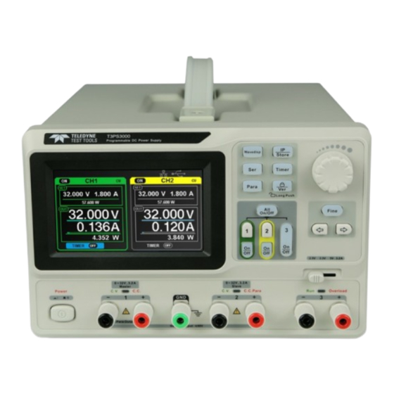
Page 10: Front Panel
1.3 Front Panel Description Description ○ ○ Display Area CH3 Voltage Selector Switch ○ ○ Carrying Handle Power Switch System parameter ○ ○ CH1 Output Terminals configuration buttons ○ ○ Multi-function knob Ground Terminal ○ ○ Fine Adjust button CH2 Output Terminals ○... - Page 11 Buttons for setting parameters Press the button to turn on/off the waveform display interface. Press the button to set series mode of CH1 / CH2. The logo is displayed to indicate series mode is on. Press the button to set parallel mode of CH1 / CH2. The logo is displayed to indicate parallel mode in on.
- Page 12 Other buttons Select the digit position by moving the cursor using the Right or Left Direction buttons and the Fine button. Press the button to move the cursor. The output terminals on the front panel The output terminals of CH1, CH2 and CH3 are clearly labelled and include a positive terminal in red, a negative terminal in black, and a common ground in green for CH1 and CH2.
-
Page 13: User Interface
1.4 User Interface ○ Parallel/Series logo: The logo will be displayed when the corresponding parallel or series mode is on. ○ Channel Number (CH1 or CH2) ○ Operating mode logo: The corresponding letters will be displayed depending on which mode the channel is in, either CV or CC mode. ○... -
Page 14: Rear Panel
1.5 Rear Panel ○ Product safety / warning message. ○ The DIP switch selection for the AC input voltage. This should be set before use. ○ The description of the AC input voltage and fuse ratings. ○ AC power socket. ○... -
Page 15: Output Check
1.6 Output Check The output check includes voltage check of all channels with no load, and current check with a short circuit so as to make sure that the instrument is working correctly. Voltage Output Check 1. Within no load, turn on the power, and make sure the current setting values of all channels are not zero. -
Page 16: Chapter 2 Control Panel Operation
Chapter 2 Control Panel Operation In this chapter the function and operation of the power supply control panel will be covered in detail. Output summary CH1/CH2 independent output CH3 independent output Series output Parallel output LAN setting Save and recall Timer Waveform display Version information... -
Page 17: Output Summary
2.1 Output Summary The power supply has three independent outputs, two of which have adjustable voltage or current values (depending on the operating mode) and the third having selectable 2.5V, 3.3V or 5.0V output. Independent / Parallel / Series The power supply outputs of CH1 and CH2 have three output modes: independent, parallel and series, which can be selected through the track switch on the front panel. - Page 18 Understanding Constant Voltage and Constant Current Modes Part A, CV Mode Part B, CC Mode Part C, CV Mode Time The Red line represents Voltage. The Blue line represents Current. The level between the two points represents the user preset maximum output voltage level in this example.
-
Page 19: Ch1/Ch2 Independent Output
2.2 CH1 / CH2 Independent Output Mode When CH1 and CH2 are working in independent mode, they each output their set voltages and currents on their respective output terminals as shown below. They are isolated from ground. Output rating: 0~32V / 0~3.2A per channel for channels 1 and 2. Operation 1. -
Page 20: Ch3 Independent Mode
2.3 CH3 Independent Mode CH3 is independent from CH1 and CH2, and it therefore does not work in parallel or in series mode with CH1 or CH2. Its voltage and current ratings can be set to any of the preset values of 2.5V, 3.3V, or 5V at up to 3.2A. Output ratings: 2.5V / 3.3V / 5V at up to 3.2A. -
Page 21: Ch1/Ch2 Series Mode
2.4 CH1 / CH2 Series Mode In series mode, CH1 and CH2 are linked internally into one channel which is controlled by CH1, and the output voltage value is twice that of a single channel. Output rating 0~64V / 0~3.2A Operation:... -
Page 22: Ch1/Ch2 Parallel Mode
2.5 CH1 / CH2 Parallel Mode In parallel mode, CH1 and CH2 are linked internally to one channel, which is controlled by CH1. Its output current value is twice as much as that of the single channel current value. Output rating 0~32V / 0~6.4A Operation: 1. -
Page 23: Lan Setting
2.6 LAN Setting Operation: 1. Connect the T3PS3000 PSU to your local area network using the network cable. 2. Press the “IP/Store” button to enter the LAN setting interface. 3. Press the direction button to go to the DHCP line. Turn the multi-function knob... -
Page 24: Save And Recall
2.7 Save and Recall Five group setups can be saved in memory. The contents of the setup file include: ● Independent/series/parallel mode ● Output voltage/current value ● Timer setup Save Setup 1. Set the state that you want to save. 2. -
Page 25: Timer
2.8 Timer The timer works in the Independent output mode, and can save five timing setups, each of which is independent from the others. You can set any voltage/current value that is within the range of the instrument. The timer supports consecutive output, and the longest time of each group is 10000s. - Page 26 Turn the Timer On or Off Method 1: 1. Press the “1” or ”2” button to select the desired channel on the main interface. 2. Press the direction button to move the cursor to the “TIMER” menu. 3. Turn the multi-function knob to change the Timer setting to “ON” or "OFF". 4.
- Page 27 If you press the “On/Off” button to turn off the output when the timer is running, the countdown will stop. The countdown will resume when the channel output is turned on again. The Timer will automatically turn off when the time reduces to 0. Note: The timer function is invalid when the series mode or parallel mode is turned on.
-
Page 28: Waveform Display
2.9 Waveform Display The T3PS3000 can display the changing voltage and current values in real time as a waveform plot. Operation: 1. Select CH1 / CH2, then set the voltage / current parameters. 2. Press the “Wavedisp” button to enter the Waveform Display interface. -
Page 29: Version Information
2.10 Version Information Short press of the button to enter Version Information interface. Long press of the button to lock the interface, which will lock all the buttons and knobs. The “lock” icon will be displayed. Long press again to turn off the keylock function. The “lock” icon will no longer be illuminated and the knobs and buttons will become functional again. -
Page 30: Chapter 3 Remote Control
SCPI (Standard Commands for Programmable Instruments) is an ASCII based programming language that can be used to control the power supply from a remote computer installed with NI Measurement & Automation software. In this chapter, we introduce the SCPI commands supported by the T3PS3000. Quick Start... -
Page 31: Syntax Conventions
3.1 Syntax Conventions Most commands are written in a mixture of upper- case and lower-case letters. The upper-case letters indicate the command's abbreviated spelling, which yields shorter program lines. For better program readability, use the long form. For example: [{CH1|CH2}:]VOLTage <voltage> For the keyword VOLTage, you can type VOLT or VOLTage in any combination of upper- or lower-case letters. -
Page 32: Command List
3.2 Command List 1. *IDN? 2. *SAV 3. *RCL 4. INSTrument Subsystem 5. MEASure Subsystem 6. CURRent Subsystem 7. VOLTage Subsystem 8. OUTPut Subsystem 9. TIMEr Subsystem 10. SYSTem Subsystem 11. IPaddr Subsystem 12. MASKaddr Subsystem 13. GATEaddr Subsystem 14. DHCP Subsystem Quick Start... -
Page 33: Command Description
Query the manufacturer, product type, series No., software version and hardware version Return Info Manufacturer, product type, series No., software version, hardware version Typical Return T3, Teledyne Test Tools, T3PS3000, PS00001130025, 1.01.01.01.02,V3.0 2. *SAV Command format *SAV {1|2|3|4|5} Description Save current state in nonvolatile memory... - Page 34 Command format INSTrument? Description Query the current operating channel Example INSTrument? Typical Return 5. MEASure Command format MEASure: CURRent? [{CH1|CH2}] Description Query current value for specified channel, if there is no specified channel, query the current channel Example MEASure: CURRent? CH1 Typical Return 3.000 Command format...
- Page 35 6. CURRent Command format [{CH1|CH2}:]CURRent <current> Description Set current value of the selected channel Example CH1:CURRent 0.5 Command format [{CH1|CH2}:]CURRent? Description Query the current value of the selected channel Example CH1: CURRent? Typical Return 0.500 7. VOLTage Command format [{CH1|CH2}:]VOLTage <voltage> Description Set voltage value of the selected channel Example...
- Page 36 8. OUTPut Command format OUTPut {CH1|CH2|CH3},{ON|OFF} Description Turn on/off the specified channel output Example OUTPut CH1,ON Command format OUTPut:TRACK {0|1|2} Description Select operation mode. Parameters {0|1|2} mean independent, series and parallel, respectively Example OUTPut: TRACK 0 Command format OUTPut:WAVE {CH1|CH2},{ON|OFF} Description Turn on/off the Waveform Display function of specified channel...
- Page 37 Example TIMEr:SET? CH1,2 Typical Return 3,0.5,2 Command format TIMEr {CH1|CH2},{ON|OFF}; Description Turn on/off Timer function of specified channel Example TIMEr CH1,ON 10. SYSTem Command format SYSTem: ERRor? Description Query the error code and the information regarding the equipment Typical Return 0 No Error Command format SYSTem: VERSion?
- Page 38 Bit No. Corresponding state 0: CH1 CV mode; 1: CH1 CC mode 0: CH2 CV mode; 1: CH2 CC mode 01: Independent mode; 10: Parallel mode 0: CH1 OFF 1: CH1 ON 0: CH2 OFF 1: CH2 ON 0: TIMER1 OFF 1: TIMER1 ON 0: TIMER2 OFF 1: TIMER2 ON...
- Page 39 Command format MASKaddr? Description Query the current subnet mask of the instrument Typical Return 255.255.255.0 13. GATEaddr Command format GATEaddr <GateWay> Description Assign a gateway for the instrument Example GATEaddr 10.11.13.1 Note The command is invalid when DHCP is used Command format GATEaddr? Description...
-
Page 40: Chapter 4 Troubleshooting
Chapter 4 Troubleshooting Question 1: What if a short circuit occurs on the output terminal? Answer 1: There are over current protection and short circuit protection inside the power supply, so current will be kept within a safe range. Question 2: Is there a problem when the CH3 overload indicator is lit? Answer 2: No, that only means the current value has reached 3.2 A, which is the maximum value within its range. - Page 42 The Teledyne Test Tools brand expands on the Teledyne LeCroy product portfolio by adding a comprehensive range of test equipment solutions for its customers. The new range of product solutions deliver engineers with a broad range of quality test solutions that enables speed to market product validation and design.
Need help?
Do you have a question about the T3PS3000 and is the answer not in the manual?
Questions and answers