
Related Manuals for Teledyne T3PS40381P


Summary of Contents for Teledyne T3PS40381P
- Page 1 T3PS40381P, T3PS60251P, T3PS062001P Programmable DC Power Supplies Programming Manual...
- Page 2 Teledyne LeCroy company. The information in this manual was correct at the time of printing. However, Teledyne LeCroy continues to improve products and reserves the rights to change specification, equipment, and maintenance procedures at any time without notice.
-
Page 3: Table Of Contents
Table of Contents Table of Contents SAFETY INSTRUCTIONS ..........4 GETTING STARTED ............9 T3PS Series Overview ..........10 Appearance ............13 Configuration Settings ........... 20 REMOTE CONTROL ............28 Interface Configuration .......... 29 Command Syntax ........... 48 Command List ............51 Status Register Overview ........118 Error List ..............131 APPENDIX .............. -
Page 4: Safety Instructions
T3PS Series Programming Manual AFETY INSTRUCTIONS This chapter contains important safety instructions that you must follow during operation and storage. Read the following before any operation to insure your safety and to keep the instrument in the best possible condition. Safety Symbols These safety symbols may appear in this manual or on the instrument. - Page 5 SAFETY INSTRUCTIONS Do not dispose electronic equipment as unsorted municipal waste. Please use a separate collection facility or contact the supplier from which this instrument was purchased. Safety Guidelines Do not place any heavy object on the T3PS. General Guideline Avoid severe impact or rough handling that ...
- Page 6 T3PS Series Programming Manual Use proper power cord. Maintain ground. The AC inlet ground is connected to the frame of the instrument. Connect line cords only to outlets with safety ground contacts. Interrupting the protective conductor (safety ground WARNING wire) inside or outside the instrument, or disconnecting the safety ground terminal, creates a hazardous situation.
- Page 7 SAFETY INSTRUCTIONS Location: Indoor Storage environment Temperature: -25°C to 70°C Relative Humidity: ≤90%(no condensation) Do not dispose this instrument as unsorted Disposal municipal waste. Please use a separate collection facility or contact the supplier from which this instrument was purchased.
- Page 8 T3PS Series Programming Manual Power cord for the United Kingdom When using the power supply in the United Kingdom, make sure the power cord meets the following safety instructions. NOTE: This lead/appliance must only be wired by competent persons WARNING: THIS APPLIANCE MUST BE EARTHED IMPORTANT: The wires in this lead are coloured in accordance with the following code: Green/ Yellow:...
-
Page 9: Getting Started
GETTING STARTED ETTING STARTED This chapter describes the power supply, including its main features and front / rear panel introduction. After going through the overview, please read the theory of operation to become familiar with the operating modes, protection modes and other safety considerations. T3PS Series Overview .......... -
Page 10: T3Ps Series Overview
The T3PS series consists of 3 models, covering a number of different current, voltage and power capacities: Model name Voltage Rating Current Rating Power T3PS062001P 200A 1200W T3PS40381P 1520W T3PS60251P 1500W Minimum voltage guaranteed to 0.2% of rating voltage. Minimum current guaranteed to 0.4% of rating current. -
Page 11: Main Features
GETTING STARTED Main Features High power density: 1500W in 1U Performance Universal input voltage 85~265Vac, continuous operation. Output voltage up to 60V, current up to 200A. Active power factor correction. Features Parallel master/slave operation with active ... -
Page 12: Accessories
T3PS Series Programming Manual Accessories Before using the T3PS power supply unit, check the package contents to make sure all the standard accessories are included. Standard Part number Description Qty. Accessories Output terminal cover Analog connector plug kit Output terminal M8 bolt set (6V~60V model) Input terminal cover 1U Handle, ROHS... -
Page 13: Appearance
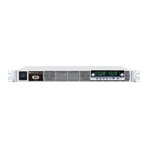
GETTING STARTED Appearance Front Panel Display Area Voltage Current VOLTAGE CURRENT Lock/ Local PROT Function Test Shift Output : Long Push Unlock ALM_CLR 9 10 12 13 Used to turn the power on/off. Power Switch USB A port for data transfer, USB A Port loading test scripts etc. - Page 14 T3PS Series Programming Manual Used to lock all front panel Lock/Local Lock/Local buttons other than the Output Button Button or it switches to local Unlock mode. (Long push) Used to unlock the Unlock Button front panel buttons. Used to set and display OVP, OCP PROT Button PROT and UVL.
- Page 15 GETTING STARTED Used to enable the functions that 11. Shift Button Shift are written in blue characters below certain buttons. Used to turn the output on or off. 12. Output Output Button Lights in green when the output is 13. Output ON...
-
Page 16: Display And Operation Panel
T3PS Series Programming Manual Display and Operation Panel Display Area VOLTAGE CURRENT Displays the voltage or the parameter number of a 14. Voltage Meter Function parameter. Displays the current or the value of a Function 15. Current parameter. Meter Lights in green during constant voltage mode. 16. - Page 17 GETTING STARTED Lights up when CC Slew Rate Priority is enabled. 24. ISR LED Lights in green when the memory value are being 25. M1 LED recalled or saved. Lights in green when the memory value are being 26. M2 LED recalled or saved.
-
Page 18: Rear Panel
T3PS Series Programming Manual Rear Panel DC OUTPUT RS485 / 232 ANALOG PROGRAMMING 240V S LS 47 63Hz 2000VA MAX. AC INPUT REMOTE SENSE Wire clamp connector. AC Input AC INPUT Output terminals for 6V to 60V DC Output models. USB port for controlling the T3PS remotely. - Page 19 GETTING STARTED RS485 support via user supplied cable with DB9 / RJ45 connectors wired according to the table on page 124 of the T3PS user manual. RS 485 / 232 RJ-45 connector that is used to Remote-OUT daisy chain power supplies with the Remote-IN port to form a communication bus.
-
Page 20: Configuration Settings
T3PS Series Programming Manual Configuration Settings Setting Normal Function Settings The Normal Function settings, F-01-F-61, F-70-F-78, F-88-F-89 and F100-F122 can be easily configured with the Function key. Ensure the load is not connected. Ensure the output is off. Function settings F-90-98 can only be viewed. - Page 21 GETTING STARTED 4. Use the Current knob to set the Current parameter for the chosen F setting. Press the Voltage knob to save the Voltage configuration setting. ConF will be displayed when it is configuring. VOLTAGE CURRENT Press the Function key again to exit Exit Function the configuration settings.
- Page 22 T3PS Series Programming Manual VOLTAGE CURRENT 3. Rotate the Voltage knob to change Voltage the F setting. F-90-F-98 Range 4. Use the Current knob to set the Current parameter for the chosen F setting. Press the Voltage knob to save the Voltage configuration setting.
- Page 23 V-I mode slew rate select F-03 2 = CV slew rate priority (CVLS) 3 = CC slew rate priority (CVLS) 0.001-0.06V/msec (T3PS062001P) Rising voltage slew rate F-04 0.001-0.4V/msec (T3PS40381P) 0.001-0.6V/msec (T3PS60251P) 0.001-0.06V/msec (T3PS062001P) Falling voltage slew rate F-05 0.001-0.4V/msec (T3PS40381P) 0.001-0.6V/msec (T3PS60251P) 0.001-2A/msec (T3PS062001P)
- Page 24 0 = Disable USB, 1 = Full Speed, 2 = Setup rear USB Speed F-22 Auto Detect Speed 0 = Teledyne LeCroy, 1 = TDK GEN, 2 SCPI Emulation F-26 = Agilent 5700, 3 = Kikusui PWX, 4 = AMREL SPS...
- Page 25 GETTING STARTED Gateway-1 F-47 0-255 Gateway-2 F-48 0-255 Gateway-3 F-49 0-255 Gateway-4 F-50 0-255 DNS address -1 F-51 0-255 DNS address -2 F-52 0-255 DNS address-3 F-53 0-255 DNS address-4 F-54 0-255 Socket Server 0 = Disable, 1 = Enable F-57 Enable/Disable Show Socket Server Port F-58...
- Page 26 T3PS Series Programming Manual I, J, K, L = Test Command Build (YYYYMMDD) M,N = Reserved O,P = Option module Power On Configuration Settings* 0 = Control by Local 1 = Control by External Voltage 2 = Control by External Resistor - Rising F-90 CV Control...
- Page 27 GETTING STARTED Output State When 0 = OFF F103 Receiving Trigger 1 = ON Apply Voltage Setting on 0-rated voltage (only applicable when F104 Trigger F102 =2) Apply Current Setting on 0-rated current (only applicable F105 Trigger when F102 =2) Recall memory number F106 1-3 (M1-M3)
-
Page 28: Remote Control
T3PS Series Programming Manual EMOTE CONTROL This chapter describes basic configuration of IEEE488.2 based remote control. Interface Configuration .......... 29 USB Remote Interface .............. 29 Configuration ............... 29 Function Check ..............30 UART Remote Interface ............31 Configure UART ..............31 UART Function Check ............ -
Page 29: Interface Configuration
REMOTE CONTROL Interface Configuration USB Remote Interface Configuration PC side connector Type A, host Configuration T3PS side Rear panel Type B, slave connector 1.1/2.0 (full speed/high speed) Speed CDC (communications device USB Class class) 1. Connect the USB cable to the rear Steps panel USB B port. -
Page 30: Function Check
USB remote control (page 29). *idn? This should return the Manufacturer, Model number, Serial number, and Firmware version in the following format. Teledyne, T3PS40381P,TW123456,T0.01.12345678 Manufacturer: Teledyne Model number: T3PS40381P Serial number: TW123456 Firmware version: T0.01.12345678... -
Page 31: Uart Remote Interface
REMOTE CONTROL UART Remote Interface Configure UART The T3PS uses the IN & OUT ports for UART Overview communication coupled with RS232 or RS485 adapters. The pin outs for the adapters are shown below. RS232 cable with DB-9 Connector Remote IN Port Remarks DB9 connector Pin No. - Page 32 T3PS Series Programming Manual 1. Connect the RS232 serial cable or Steps RS 485 / 232 RS485 serial cable to the Remote IN port on the real panel. Connect the other end of the cable to the PC. 2. Press the Function key to enter the Normal configuration settings.
-
Page 33: Uart Function Check
RS232 or RS485 remote control (page 31). *idn? This should return the Manufacturer, Model number, Serial number, and Firmware version in the following format: Teledyne, T3PS40381P,TW123456,T0.01.12345678 Manufacturer: Teledyne Model number : T3PS40381P Serial number : TW123456 Firmware version : T0.01.12345678... -
Page 34: Multiple Unit Connection
T3PS Series Programming Manual Multiple Unit Connection The T3PS power supplies can have up to 31 units daisy-chained together using the 8 pin connectors (IN OUT ports) on the rear panel. The first unit (master) in the chain is remotely connected to a PC using RS232 or RS485 (Legacy Multi-Drop mode), or USB, GPIB or LAN (Multi-Drop mode). - Page 35 REMOTE CONTROL chained together. Unit #N Unit #2 Unit #1 RS 485 / 232 RS 485 / 232 RS 485 / 232 To PC End terminal Slave serial Slave serial RS232/RS485 connector cable(black plug) cable(black plug) serial cable 5. Terminate the OUT port of the last unit with the end terminal connector 6.
- Page 36 T3PS Series Programming Manual F-72 = 1 Set to 8 data bits. F-73 = 0 Parity to none. F-74 = 0 1 Stop bit. Set the UART TCP to TDK F-75 = 1 (emulation mode). Set the address of each slave to a F-76 = 00~30 unique address identifier 8.
-
Page 37: Multi-Drop Mode
REMOTE CONTROL Multi-Drop mode 1. Check the F-89 (System version and build date) Operation settings first on all units. The two parameters O and P (Option Module) must be the same on all units before any multiple unit connection can be established. - Page 38 T3PS Series Programming Manual Set the address of the unit. It must F-76 = 00~30 be a unique address identifier. 9. Set the Multi-Drop setting parameter (F-77) to Slave for all slave units. F-77 = 2 Set the Multi-Drop setting to slave. 10.
- Page 39 REMOTE CONTROL RS-485 slave serial link pin assignment Slave serial link 8 Pin Connector (IN) 8 Pin Connector (OUT) cable with RJ-45 Pin No. Name Pin No. Name shielded Housing Shield Housing Shield connectors TXD - TXD - TXD + TXD + RXD - RXD -...
-
Page 40: Multiple Units Function Check
T3PS Series Programming Manual Multiple units Function Check Invoke a terminal application such as Realterm. Functionality check To check the COM port No, see the Device Manager in the PC. For WinXP; Control panel → System → Hardware tab. Below shows examples using the Legacy Multi- Drop mode and the Multi-Drop mode. -
Page 41: Configure Ethernet Connection
REMOTE CONTROL Configure Ethernet Connection The Ethernet interface can be configured for a number of different applications. Ethernet can be configured for basic remote control or monitoring using a web server or it can be configured as a socket server. The T3PS series supports both DHCP connections so the instrument can be automatically connected to an existing network or alternatively, network settings can be manually configured. - Page 42 T3PS Series Programming Manual 2. Press the Function key to enter the Function Normal configuration settings. Set the following LAN settings: F-36 = 1 Enable LAN F-37 = 0 Disable DHCP F-39 = 172 IP Address part 1 of 4 F-40 = 16 IP Address part 2 of 4 F-41 = 5...
-
Page 43: Socket Server Function Check
REMOTE CONTROL Socket Server Function Check To test the socket server functionality, National Background Instruments Measurement and Automation Explorer can be used. This program is available on the NI website, www.ni.com., via a search for the VISA Run-time Engine page, or “downloads” at the following URL, http://www.ni.com/visa/ Operating System: Windows XP, 7, 8 Requirements... - Page 44 T3PS Series Programming Manual 4. Select Manual Entry of Raw Socket from the popup window. 5. Enter the IP address and the port number of the T3PS. The port number is fixed at 2268. 6. Click the Validate button. 7. A popup will appear if a connection is successfully established.
- Page 45 REMOTE CONTROL 9. Next configure the Alias (name) of the T3PS connection. In this example the Alias is: T3PS_DC1 10. Click finish. T3PS_DC1 11. The IP address of the T3PS will now appear under Network Devices in the configuration panel. Select this icon now. 12.
- Page 46 T3PS Series Programming Manual 13. Click the Configuration icon, 14. Click on I/O Settings. 15. Make sure the Enable Termination Character check box is checked, and the terminal character is \n (Value: xA). 16. Click Apply Changes. 17. Click the Input/Output icon. 18.
- Page 47 REMOTE CONTROL 20. The *IDN? query will return the Manufacturer, model name, serial number and firmware version in the dialog box. Teledyne, T3PS40381P,TW123456,T0.02.20131205 Teledyne,T3PS40381P, T0.02.20131205\n...
-
Page 48: Command Syntax
T3PS Series Programming Manual Command Syntax Partial compatibility Compatible IEEE488.2 Standard Partial compatibility SCPI, 1999 SCPI commands follow a tree-like structure, Command organized into nodes. Each level of the command Structure tree is a node. Each keyword in a SCPI command represents each node in the command tree. - Page 49 REMOTE CONTROL A query is a simple or compound Query command followed by a question mark (?). A parameter (data) is returned. meas:curr:dc? Example Two or more commands on the Compound same command line. Compound commands are separated with either a semi-colon (;) or a semi- colon and a colon (;:).
- Page 50 T3PS Series Programming Manual Long form STATus:OPERation:NTRansition? STATUS:OPERATION:NTRANSITION? status:operation:ntransition? Short form STAT:OPER:NTR? stat:oper:ntr? Commands that contain square brackets indicate Square Brackets that the contents are optional. The function of the command is the same with or without the square bracketed items, as shown below. Both “DISPlay:MENU[:NAME]?”...
-
Page 51: Command List
REMOTE CONTROL Command List :ABORt ..................55 :ABORt :APPLy ..................55 :APPLY Commands :DISPlay:MENU[:NAME] ............ 56 Display :DISPlay[:WINDow]:TEXT:CLEar ........56 Commands :DISPlay[:WINDow]:TEXT[:DATA] ......... 57 :DISPlay:BLINk ..............57 :INITiate:CONTinuous[:TRANsient] ......... 58 Initiate :INITiate[:IMMediate]:NAME ..........58 Commands :INITiate[:IMMediate][:TRANsient] ........59 :INSTrument:SCAN ............... 60 Instrument :INSTrument:SELect ............. - Page 52 T3PS Series Programming Manual :SENSe:AVERage:COUNt ........... 68 Sense Commands :STATus:OPERation[:EVENt] ..........69 Status :STATus:OPERation:CONDition ........69 Commands :STATus:OPERation:ENABle ..........70 :STATus:OPERation:PTRansition ........70 :STATus:OPERation:NTRansition........70 :STATus:QUEStionable[:EVENt] ........71 :STATus:QUEStionable:CONDition ........71 :STATus:QUEStionable:ENABle ........71 :STATus:QUEStionable:PTRansition ......... 71 :STATus:QUEStionable:NTRansition ........ 72 :STATus:QUEStionable:INSTrument: ISUMmary<n>[:EVENt] ............
- Page 53 REMOTE CONTROL [:SOURce]:VOLTage:PROTection[:LEVel] ...... 83 [:SOURce]:VOLTage:PROTection:TRIPped ....83 [:SOURce]:VOLTage:SLEWrate:RISing ......84 [:SOURce]:VOLTage:SLEWrate:FALLing ......84 :SYSTem:BEEPer[:IMMediate] ..........87 System :SYSTem:CONFigure:BEEPer[:STATe] ......88 Commands :SYSTem:CONFigure:BLEeder[:STATe] ......88 :SYSTem:CONFigure:CURRent:CONTrol ....... 88 :SYSTem:CONFigure:VOLTage:CONTrol ...... 89 :SYSTem:CONFigure:OUTPut:PON[:STATe] ....91 :SYSTem:CONFigure:PROTection:RECovery ....92 :SYSTem:CONFigure:MSLave ..........92 :SYSTem:CONFigure:OUTPut:EXTernal:MODE ..
- Page 54 T3PS Series Programming Manual :SYSTem:COMMunicate:USB:FRONt:STATe ....107 :SYSTem:COMMunicate:USB:REAR:MODE ....107 :SYSTem:COMMunicate:USB:REAR:STATe ....108 :SYSTem:ERRor ..............108 :SYSTem:KLOCk ..............108 :SYSTem:KEYLock:MODE ..........108 :SYSTem:ERRor:ENABle ...........109 :SYSTem:LANGuage:EMULation ........109 :SYSTem:LANGuage:[:SELect] ..........109 :SYSTem:PRESet ..............110 :SYSTem:VERSion ...............110 :SYSTem:REBoot ..............110 :TRIGger:OUTPut:SOURce ..........111 Trigger :TRIGger:OUTPut[:IMMediate] ........111 Commands :TRIGger[:TRANsient]:SOURce ........112 :TRIGger[:TRANsient][:IMMediate] .........112 *CLS ..................113 Common *ESE ..................113 Commands...
-
Page 55: Abort :Abort
REMOTE CONTROL Abort Commands :ABORt ..................55 :ABORt The :ABORt command will cancel any triggered Description actions. Syntax :ABORt Apply Commands :APPLy ..................55 :APPLy Query The apply command sets the voltage and current Description at the same time. Syntax :APPLy {<NRf>(V)|MINimum|MAXimum[,<NRf>(A)|MINimu m|MAXimum]}... -
Page 56: Display :Display:menu[:Name]
T3PS Series Programming Manual Display Commands :DISPlay:MENU[:NAME] ............ 56 :DISPlay[:WINDow]:TEXT:CLEar ........56 :DISPlay[:WINDow]:TEXT[:DATA] ......... 57 :DISPlay:BLINk ..............57 :DISPlay:MENU[:NAME] Query The DISPlay MENU command selects a screen Description menu or queries the current screen menu. Syntax :DISPlay:MENU[:NAME] <NR1> Query Sytax :DISPlay:MENU[:NAME]? Description Parameter/... -
Page 57: Display[:Window]:Text[:Data]
REMOTE CONTROL :DISPlay[:WINDow]:TEXT[:DATA] Query Sets or queries the data text that will be written to Description the display. Writing to the display will overwrite data that is currently on the screen. Overwriting a display area with a shorter string may or may not overwrite the screen. -
Page 58: Initiate Commands
T3PS Series Programming Manual Initiate Commands :INITiate:CONTinuous[:TRANsient] ......... 58 :INITiate[:IMMediate]:NAME ..........58 :INITiate[:IMMediate][:TRANsient] ........59 :INITiate:CONTinuous[:TRANsient] Query This command continuously initiates software Description triggers for the transient or output triggers. Syntax :INITiate:CONTinuous[:TRANsient] {<bool>|OFF|ON} Query Syntax :INITiate:CONTinuous[:TRANsient]? Parameter OFF | 0 ON | 1 Return parameter 0 Example... -
Page 59: Initiate[:Immediate][:Transient]
REMOTE CONTROL :INITiate[:IMMediate][:TRANsient] This command controls the enabling of output Description triggers. When a trigger is enabled, a trigger causes the specified action to occur. If the trigger system is not enabled, all triggers are ignored. Syntax :INITiate[:IMMediate][:TRANsient] Example INIT... -
Page 60: Instrument Commands
T3PS Series Programming Manual Instrument Commands :INSTrument:SCAN ............... 60 :INSTrument:SELect .............. 60 :INSTrument:STATe .............. 60 :INSTrument:DISPlay ............61 :INSTrument:SCAN Query Links the units which could be scanned from system Description when using Multi-Drop mode. Syntax :INSTrument:SCAN :INSTrument:SELect Query Specifies the address of the unit to which Description communication will be established when using the Multi-Drop mode. -
Page 61: Instrument:display
REMOTE CONTROL Return parameter <NR1>,<NR1> 0~1073741823, 0~30 (1073741823=2^30-1) First value: Each bit of the binary value corresponds to a unit from 0 to 30 (LSB to MSB). The bit will be set to 1 when the corresponding unit is on-line. Second value: This value represents the master address. -
Page 62: Measure :Measure[:Scalar]:All[:Dc]
T3PS Series Programming Manual Measure Commands :MEASure[:SCALar]:ALL[:DC] ..........62 :MEASure[:SCALar]:CURRent[:DC] ........62 :MEASure[:SCALar]:VOLTage[:DC] ........62 :MEASure[:SCALar]:POWer[:DC] ........63 :MEASure[:SCALar]:ALL[:DC] Query Takes a measurement and returns the average Description output current and voltage Syntax :MEASure[:SCALar]:ALL[:DC]? <voltage>,<current> Return parameter "+0.0000,+0.0000" Returns the voltage (V) and current (A), respectively. -
Page 63: Measure[:Scalar]:Power[:Dc]
REMOTE CONTROL :MEASure[:SCALar]:POWer[:DC] Query Takes a measurement and returns the average Description output power. Syntax :MEASure[:SCALar]:POWer[:DC]? Returns the power measured in Return "+0.0000" watts. -
Page 64: Memory :Memory:triggered
T3PS Series Programming Manual Memory Commands :MEMory:TRIGgered ............. 64 :MEMory:TRIGgered Query Sets or queries which memory is loaded when a Description trigger input is received and the trigger input is configured to load a memory setting. Related :SYSTem:CONFigure:TRIGger:INPut:SOURce Commands :SYSTem:CONFigure:TRIGger:OUTPut:SOURce Syntax :MEMory:TRIGgered {<NR1>|MINimum|MAXimum} Return Syntax... -
Page 65: Output Commands
REMOTE CONTROL Output Commands :OUTPut:DELay:ON ............. 65 :OUTPut:DELay:OFF ............65 :OUTPut:MODE ..............66 :OUTPut[:STATe][:IMMediate] ........... 66 :OUTPut[:STATe]:TRIGgered ..........66 :OUTPut:PROTection:CLEar ..........67 :OUTPut:PROTection:TRIPped ......... 67 :OUTPut:DELay:ON Query Sets the Delay Time in seconds for turning the Description output on. The delay is set to 0.00 by default. Syntax :OUTPut:DELay:ON {<NR2>|MINimum|MAXimum} Query Syntax... -
Page 66: Output:mode
T3PS Series Programming Manual :OUTPut:MODE Query Sets the T3PS output mode. This is the equivalent Description to the F-03 (V-I Mode Slew Rate Select) settings. Syntax :OUTPut:MODE {<NR1>|CVHS|CCHS|CVLS|CCLS} Return Syntax :OUTPut:MODE? CVHS | 0 CV high speed priority Parameter CCHS | 1 CC high speed priority CVLS | 2 CV slew rate priority CCLS | 3 CC slew rate priority Returns the output mode. -
Page 67: Output:protection:clear
REMOTE CONTROL Turns the output on when a software ON | 1 trigger is generated (*TRG). Returns output trigger status of the Return parameter <bool> instrument. :OUTPut:PROTection:CLEar Clears over-voltage, over-current and over- Description temperature (OVP, OCP, OTP) protection circuits. It also clears the shutdown and sense protection circuit. - Page 68 T3PS Series Programming Manual Sense Commands :SENSe:AVERage:COUNt ........... 68 :SENSe:AVERage:COUNt Query Sets or queries the level of smoothing for the Description average setting. Syntax :SENSe:AVERage:COUNt {<NR1>|LOW|MIDDle|HIGH} Return Syntax :SENSe:AVERage:COUNt? Low setting Parameter LOW | 0 Middle setting MIDDle | 1 High setting HIGH | 2 Returns the average setting.
-
Page 69: Status :Status:operation[:Event]
REMOTE CONTROL Status Commands For an overview of all the status registers, their associated register contents and the system diagram, please see the status overview on page 117 :STATus:OPERation[:EVENt] ..........69 :STATus:OPERation:CONDition ........69 :STATus:OPERation:ENABle ..........70 :STATus:OPERation:PTRansition ........70 :STATus:OPERation:NTRansition ........ -
Page 70: Status:operation:enable
T3PS Series Programming Manual Returns the bit sum of the Operation Return <NR1> Condition register. :STATus:OPERation:ENABle Query Sets or queries the bit sum of the Operation Status Description Enable register. Syntax :STATus:OPERation:ENABle <NR1> Query Syntax :STATus:OPERation:ENABle? 0~32767 Parameter <NR1> 0~32767 Return parameter <NR1>... -
Page 71: Status:questionable[:Event]
REMOTE CONTROL :STATus:QUEStionable[:EVENt] Query Queries the bit sum of the Questionable Status Description Event register. This query will also clear the contents of the register. Query Syntax :STATus:QUEStionable[:EVENt]? 0~32767 Return parameter <NR1> :STATus:QUEStionable:CONDition Query Queries the status (bit sum) of the Questionable Description Status register. -
Page 72: Status:questionable:ntransition
T3PS Series Programming Manual 0~32767 Return parameter <NR1> :STATus:QUEStionable:NTRansition Query Sets or queries the negative transition filter of the Description Questionable Status register. Syntax :STATus:QUEStionable:NTRansition <NR1> Query Syntax :STATus:QUEStionable:NTRansition? 0~32767 Parameter <NR1> 0~32767 Return parameter <NR1> :STATus:QUEStionable:INSTrument: ISUMmary<n>[:EVENt] Query Queries the bit sum of the Questionable Description Instrument Summary Status Event register. -
Page 73: Status:questionable:instrument: Isummary
REMOTE CONTROL 0~32767 Return parameter <NR1> :STATus:QUEStionable:INSTrument: ISUMmary<n>:ENABle Query Sets or queries the bit sum of the Questionable Description Instrument Summary Status Enable register. (Multi-Drop mode). Syntax :STATus:QUEStionable:INSTrument:ISUMmary <n>:ENABle <NR1> Query Syntax :STATus:QUEStionable:INSTrument:ISUMmary <n>:ENABle? 1,2 or 3 Parameter <n> 0~32767 <NR1>...:Enable - Page 74 T3PS Series Programming Manual Operation Status Enable 0x0000 Operation Status Positive Transition 0x7FFF Operation Status Negative Transition 0x0000 Summary: The Questionable Status Enable registers and the Operation Status Enable registers are both reset to 0. The Questionable Status and Operation Status Positive Transition filters are all set high (0x7FFF) and the Negative Transition filters are all set low (0x0000).
-
Page 75: Source [:Source]:Current[:Level][:Immediate] Commands [:Amplitude]
REMOTE CONTROL Source Commands [:SOURce]:CURRent[:LEVel][:IMMediate] [:AMPLitude] ................75 [:SOURce]:CURRent[:LEVel]:TRIGgered[:AMPLitude] 76 [:SOURce]:CURRent:LIMit:AUTO ........76 [:SOURce]:CURRent:PROTection:DELay ......77 [:SOURce]:CURRent:PROTection[:LEVel] ....... 77 [:SOURce]:CURRent:PROTection:STATe ......78 [:SOURce]:CURRent:PROTection:TRIPped ....78 [:SOURce]:CURRent:SLEWrate:RISing ......79 [:SOURce]:CURRent:SLEWrate:FALLing ......79 [:SOURce]:MODE? ..............80 [:SOURce]:RESistance[:LEVel][:IMMediate] [:AMPLitude] ................80 [:SOURce]:VOLTage[:LEVel][:IMMediate] [:AMPLitude] ................81 [:SOURce]:VOLTage[:LEVel]:TRIGgered [:AMPLitude] ................ -
Page 76: [:Source]:Current[:Level]:Triggered [:Amplitude]
T3PS Series Programming Manual Maximum current level. Example SOUR:CURR:LEV:IMM:AMPL? 38.000 Returns the current level in amps. [:SOURce]:CURRent[:LEVel]:TRIGgered [:AMPLitude] Query Sets or queries the current level in amps when a Description software trigger has been generated. Syntax [:SOURce]:CURRent[:LEVel]:TRIGgered[:AMPLitude] {<NR2> (A)| MINimum|MAXimum} Query Syntax [:SOURce]:CURRent[:LEVel]:TRIGgered[:AMPLitude]? 0%~105% of the rated current output in... -
Page 77: [:Source]:Current:protection:delay
REMOTE CONTROL Example SOUR:CURR:LIM:AUTO 0 Disables the current limit. [:SOURce]:CURRent:PROTection:DELay Query Sets the Delay Time for OCP in seconds for turning Description the output off. The delay is set to 0.1 by default. Syntax [:SOURce]:CURRent:PROTection:DELay {<NR2>|MINimum|MAXimum} Query Syntax [:SOURce]:CURRent:PROTection:DELay? 0.1~2.0 seconds, where 0=no delay Parameter <NR2>... -
Page 78: [:Source]:Current:protection:state
T3PS Series Programming Manual Returns the current protection level. Return parameter <NR2> Example SOUR:CURR:PROT:LEV? +5.000 Returns the minimum possible current level in amps. [:SOURce]:CURRent:PROTection:STATe Query Turns OCP (over-current protection) on or off. Description Syntax [:SOURce]:CURRent:PROTection:STATe {<bool>|OFF|ON} Query Syntax [:SOURce]:CURRent:PROTection:STATe? Turns the OCP off. Parameter OFF | 0 Turns the OCP on. -
Page 79: [:Source]:Current:slewrate:rising
REMOTE CONTROL [:SOURce]:CURRent:SLEWrate:RISing Query Sets or queries the rising current slew rate. This is Description only applicable for CC slew rate priority mode. Syntax [:SOURce]:CURRent:SLEWrate:RISing {<NR2>(A)|MINimum|MAXimum} Query Syntax [:SOURce]:CURRent:SLEWrate:RISing? Per step is between 0.001A/msec and Parameter <NR2> rated current divided by 100 msec. Minimum rising current slew rate is 0.001A/msec. -
Page 80: [:Source]:Mode
T3PS Series Programming Manual Example SOUR:CURR:SLEW:FALL MAX Sets the falling current slew rate to the maximum. [:SOURce]:MODE? Query Returns the status of the output mode (CC, CV, Description Off) of the power supply. The interface will return “CV’ if the supply is in Constant Voltage Mode, “CC”... -
Page 81: [:Source]:Voltage[:Level][:Immediate] [:Amplitude]
REMOTE CONTROL Example SOUR:RES:LEV:IMM:AMPL 0.1 Sets the internal resistance to 100mΩ. [:SOURce]:VOLTage[:LEVel][:IMMediate] [:AMPLitude] Query Sets or queries the voltage level in volts. Description Syntax [:SOURce]:VOLTage[:LEVel][:IMMediate][:AMPLitude] {<NR2>(V)|MINimum|MAXimum} Query Syntax [:SOURce]:VOLTage[:LEVel][:IMMediate][:AMPLitude]? 0~105% of the rated output voltage in Parameter <NRf> volts. Minimum voltage level Maximum voltage level Returns the voltage level in volts Return parameter <NR2>... -
Page 82: [:Source]:Voltage:limit:auto
T3PS Series Programming Manual Example SOUR:VOLT:LEV:TRIG:AMPL 10 Sets the voltage level to 10 volts when a software trigger is generated. [:SOURce]:VOLTage:LIMit:AUTO Query Sets whether to limit the voltage setting so that it Description does not exceed the OVP setting or become lower than the UVL setting. -
Page 83: [:Source]:Voltage:protection[:Level]
REMOTE CONTROL Example SOUR:VOLT:LIM:LOW MAX Sets the UV> level to its maximum. [:SOURce]:VOLTage:PROTection[:LEVel] Query Sets or queries the overvoltage protection level. Description Syntax [:SOURce]:VOLTage:PROTection[:LEVel] {<NR2>(V)|MINimum|MAXimum} Query Syntax [:SOURce]:VOLTage:PROTection[:LEVel]? Minimum: Depends on the unit type: Parameter/Return <NR2> if Vrated * 0.1 > 5V, then Minimum = 5V, else Minimum = Vrated * 0.1 Maximum: Vrated * 1.1 Minimum OVP level... -
Page 84: [:Source]:Voltage:slewrate:rising
T3PS Series Programming Manual [:SOURce]:VOLTage:SLEWrate:RISing Query Sets or queries the rising voltage slew rate. This is Description only applicable for CV slew rate priority mode. Syntax [:SOURce]:VOLTage:SLEWrate:RISing {<NR2>(V)|MINimum|MAXimum} Query Syntax [:SOURce]:VOLTage:SLEWrate:RISing? Per step is between 0.001V/msec and Parameter <NR2> rated voltage divided by 100msec. Minimum rising voltage slew rate is 0.001V/msec. - Page 85 REMOTE CONTROL Example SOUR:VOLT:SLEW:FALL MIN Sets the falling voltage slew rate to its minimum.
- Page 86 T3PS Series Programming Manual System Function Command :SYSTem:BEEPer[:IMMediate] ..........87 :SYSTem:CONFigure:BEEPer[:STATe] ......88 :SYSTem:CONFigure:BLEeder[:STATe] ......88 :SYSTem:CONFigure:CURRent:CONTrol ....... 88 :SYSTem:CONFigure:VOLTage:CONTrol....... 89 :SYSTem:CONFigure:OUTPut:PON[:STATe] ....91 :SYSTem:CONFigure:PROTection:RECovery ....92 :SYSTem:CONFigure:MSLave ..........92 :SYSTem:CONFigure:OUTPut:EXTernal:MODE ..93 :SYSTem:CONFigure:OUTPut:EXTernal[:STATe] ..93 :SYSTem:CONFigure:MONitor:RANGe ......94 :SYSTem:CONFigure:CONTrol:RANGe......95 :SYSTem:CONFigure:TRIGger:INPut:SOURce ....
-
Page 87: System :System:beeper[:Immediate]
REMOTE CONTROL :SYSTem:COMMunicate:USB:REAR:STATe ....108 :SYSTem:ERRor ..............108 :SYSTem:KLOCk ..............108 :SYSTem:KEYLock:MODE ..........108 :SYSTem:ERRor:ENABle ........... 109 :SYSTem:LANGuage:EMULation ........109 :SYSTem:LANGuage:[:SELect] ......... 109 :SYSTem:PRESet ..............110 :SYSTem:VERSion ............... 110 :SYSTem:REBoot ..............110 :SYSTem:BEEPer[:IMMediate] Query This command causes an audible tone to be Description generated by the instrument. -
Page 88: Commands :System:configure:beeper[:State]
T3PS Series Programming Manual Example 2 :SYST:BEEP? MAX >3600 Returns the maximum settable beeper time in seconds. :SYSTem:CONFigure:BEEPer[:STATe] Query Sets or queries the buzzer state on/off. Description Syntax :SYSTem:CONFigure:BEEPer[:STATe] {<bool>|OFF|ON} Query Syntax :SYSTem:CONFigure:BEEPer[:STATe]? Turns the buzzer off. Parameter OFF | 0 Turns the buzzer on. -
Page 89: System:configure:voltage:control
REMOTE CONTROL The setting will only be valid after the power has been Note cycled. Syntax :SYSTem:CONFigure:CURRent:CONTrol { <NR1>|NONE|VOLTage|RRISing|RFALling| VISolation } Query Syntax :SYSTem:CONFigure:CURRent:CONTrol? Description Parameter <NR1> Local (Panel) control 0 | NONE External voltage control 1 | VOLTage External resistance control; 10kΩ 2 | RRISing or 5kΩ... - Page 90 T3PS Series Programming Manual The setting will only be valid after the power has been Note cycled. Syntax :SYSTem:CONFigure:VOLTage:CONTrol { <NR1>|NONE|VOLTage|RRISing|RFALling| VISolation } Query Syntax :SYSTem:CONFigure:VOLTage:CONTrol? Description Parameter <NR1> Local (Panel) control 0 | NONE External voltage control 1 | VOLTage External resistance control;...
-
Page 91: System:configure:output:pon[:State]
REMOTE CONTROL :SYSTem:CONFigure:OUTPut:PON[:STATe] Query Sets the output state at power-on. This is the Description equivalent to the F-92 (Output Status when Power ON) power on configuration settings. The setting will only be valid after the power has been Note cycled. Syntax :SYSTem:CONFigure:OUTPut:PON[:STATe] {<NR1>|{SAFE|OFF}|{FORCe|ON}|AUTO}... -
Page 92: System:configure:protection:recovery
T3PS Series Programming Manual :SYSTem:CONFigure:PROTection:RECovery Query Sets or queries how the OHP, FAN, AC-FAIL, and Description SD alarms are cleared. Syntax :SYSTem:CONFigure:PROTection:RECovery {SAFE|AUTO} Return Syntax :SYSTem:CONFigure:PROTection:RECovery? The output is not turned on Parameter SAFE automatically when the cause of the alarm is fixed. -
Page 93: System:configure:output:external:mode
REMOTE CONTROL Example SYST:CONF:MSL 2 SYST:REB Set to Master (with 2 slave units in Parallel) and reboot the unit to active the setting. :SYSTem:CONFigure:OUTPut:EXTernal :MODE Query Sets the logic used to turn the output on or off Description when using an external contact. This is the equivalent to the F-94 (External Output Logic) power on configuration settings. -
Page 94: System:configure:monitor:range
T3PS Series Programming Manual The setting will only be valid after the power has been Note cycled. Syntax :SYSTem:CONFigure:OUTPut:EXTernal[:STATe] {<bool>|OFF|ON} Return Syntax :SYSTem:CONFigure:OUTPut:EXTernal[:STATe]? External control is performed. Parameter ON | 1 External control is not performed. OFF | 0 Returns output status of the instrument. Return parameter <bool>... -
Page 95: System:configure:control:range
REMOTE CONTROL :SYSTem:CONFigure:CONTrol:RANGe Query This command is used to select the external analog Description control voltage (or resistance) range. This is the equivalent to the F-97 (Control Range) power on configuration settings. The setting will only be valid after the power has been Note cycled. -
Page 96: System:configure:trigger:input:width
T3PS Series Programming Manual MEMory | 3 Loads a memory setting on receiving a trigger. Returns the input source. Return Parameter <NR1> :SYSTem:CONFigure:TRIGger:INPut :WIDTh Query Sets or queries the input trigger pulse width. A Description setting of 0 indicates that the input trigger is controlled by the trigger input level, rather than a trigger pulse. -
Page 97: System:configure:trigger:output:width
REMOTE CONTROL MEMory | 3 Output trigger is generated when a memory setting is loaded. Returns the output source. Return Parameter <NR1> :SYSTem:CONFigure:TRIGger:OUTPut :WIDTh Query Sets or queries the output trigger pulse width. A Description setting of 0 indicates that the output trigger will go high or low, depending on the output level setting. -
Page 98: System:communicate:enable
T3PS Series Programming Manual :SYSTem:COMMunicate:ENABle Query Enables/Disables GPIB, USB or other remote Description interfaces such as Sockets and the Web Server. The setting will only be valid after the power has been Note cycled. Syntax :SYSTem:COMMunicate:ENABle {<bool> |OFF|ON,GPIB|USB|LAN|SOCKets|WEB|SERial} Query Syntax :SYSTem:COMMunicate:ENABle? {GPIB|USB|LAN|SOCKets|WEB|SERial} Disables the selected interface. -
Page 99: System:communicate:gpib[:Self]:Address
REMOTE CONTROL :SYSTem:COMMunicate:GPIB[:SELF] :ADDRess Query Sets or queries the GPIB address. Description Note The setting will only be valid after the power has been cycled. Syntax :SYSTem:COMMunicate:GPIB[:SELF]:ADDRess <NR1> Query Syntax :SYSTem:COMMunicate:GPIB[:SELF]:ADDRess? 0~30 Parameter/Return <NR1> Example SYST:COMM:GPIB:SELF:ADDR 15 SYST:REB Sets the GPIB address to 15 and reboot the unit to active the setting. -
Page 100: System:communicate:lan:gateway
T3PS Series Programming Manual :SYSTem:COMMunicate:LAN:GATeway Query Sets or queries the Gateway address. Description The setting will only be valid after the power has been Note cycled. Syntax :SYSTem:COMMunicate:LAN:GATeway <string> Query Syntax :SYSTem:COMMunicate:LAN:GATeway? Parameter/Return <string> Gateway address in string format (“address”) Applicable ASCII characters: 20H to 7EH Example SYST:COMM:LAN:GATe “172.16.0.254”... -
Page 101: System:communicate:lan:mac
REMOTE CONTROL :SYSTem:COMMunicate:LAN:MAC Query Returns the unit MAC address as a string. The Description MAC address cannot be changed. Query Syntax :SYSTem:COMMunicate:LAN:MAC? Return parameter <string> Returns the MAC address in the following format “FF-FF-FF-FF-FF-FF” Example SYST:COMM:LAN:MAC? 02-80-AD-20-31-B1 Returns the MAC address. :SYSTem:COMMunicate:LAN:DHCP Query Turns DHCP on/off. -
Page 102: System:communicate:lan:dns
T3PS Series Programming Manual :SYSTem:COMMunicate:LAN:DNS Query Sets or queries the DNS address. Description The setting will only be valid after the power has been Note cycled. Syntax :SYSTem:COMMunicate:LAN:DNS <string> Query Syntax :SYSTem:COMMunicate:LAN:DNS? Parameter/Return <string> DNS in string format ( “mask”) Applicable ASCII characters: 20H to 7EH Example SYST:COMM:LAN:DNS “172.16.1.252”... -
Page 103: System:communicate:tcpip:control
REMOTE CONTROL :SYSTem:COMMunicate:TCPip:CONTrol Query Queries the socket port number. Description Query Syntax :SYSTem:COMMunicate:TCPip:CONTrol? 0000 ~ 9999 Return parameter <NR1> Example SYST:COMM:TCP:CONT? >2268 Returns the socket port number. :SYSTem:COMMunicate:SERial:LANGuage[ :SELect] Query Sets or queries the communication protocol for the Description serial port. Syntax :SYSTem:COMMunicate:SERial:LANGuage[:SELect] {"SCPI"|"LEGACY"}... -
Page 104: System:communicate:serial[:Receive] :Transmit:bits
T3PS Series Programming Manual The setting will only be valid after the power has been Note cycled. Syntax :SYSTem:COMMunicate:SERial[:RECeive]:TRANsmit :BAUD <NR1> Query Syntax :SYSTem:COMMunicate:SERial[:RECeive]:TRANsmit :BAUD? 2400, 4800, 9600, 19200, 38400, 57600, Parameter/Return <NR1> 115200 Example SYST:COMM:SER:TRAN:BAUD? >2400 Returns the baud rate settings. SYST:COMM:SER:TRAN:BAUD 9600 SYST:REB Set the UART baud rate to 9600bps and reboot the... -
Page 105: System:communicate:serial[:Receive]:Transmit:parity
REMOTE CONTROL Example SYST:COMM:SER:TRAN:BITS? >1 Indicates that 8 data bits are used for the UART connection. SYST:COMM:SER:TRAN:BITS 1 SYST:REB Set the UART data bits to 8 data bits and reboot the unit to active the setting. :SYSTem:COMMunicate:SERial[:RECeive]:T RANsmit:PARity Query Sets or queries the parity of the UART connection. Description The setting will only be valid after the power has been Note... -
Page 106: System:communicate:serial[:Receive]:Transmit:sbits
T3PS Series Programming Manual :SYSTem:COMMunicate:SERial[:RECeive]:T RANsmit:SBITs Query Sets or queries the number of stop bits used for the Description UART connection. The setting will only be valid after the power has been Note cycled. Syntax :SYSTem:COMMunicate:SERial[:RECeive]:TRANsmit :SBITs<NR1> Query Syntax :SYSTem:COMMunicate:SERial[:RECeive]:TRANsmit :SBITs? 1 stop bit Parameter/Return... -
Page 107: System:communicate:usb:front:state
REMOTE CONTROL :SYSTem:COMMunicate:USB:FRONt:STATe Query Queries the front panel USB-A port state. Description Query Syntax :SYSTem:COMMunicate:USB:FRONt:STATe? <NR1>Absent Return parameter 0 <NR1>Mass Storage :SYSTem:COMMunicate:USB:REAR:MODE Query Sets or queries the speed of the rear panel USB B Description port. The setting will only be valid after the power has been Note cycled. -
Page 108: System:communicate:usb:rear:state
T3PS Series Programming Manual :SYSTem:COMMunicate:USB:REAR:STATe Query Queries the rear panel USB-B port state. Description Query Syntax :SYSTem:COMMunicate:USB:REAR:STATe? <NR1>Absent Return parameter 0 <NR1>Connected to the PC :SYSTem:ERRor Query Queries the error queue. The last error message is Description returned. A maximum of 32 errors are stored in the error queue. -
Page 109: System:error:enable
REMOTE CONTROL Syntax :SYSTem:KEYLock {<bool>|OFF|ON} Query Syntax :SYSTem:KEYLock? Panel lock: allow output off. Parameter/Return 0 | OFF parameter Panel lock: allow output on/off. 1 | ON :SYSTem:ERRor:ENABle Query Clears the Error Queue and enables all error Description messages to be placed in the System Error Queue. Syntax :SYSTem:ERRor:ENABle :SYSTem:LANGuage:EMULation... -
Page 110: System:preset
T3PS Series Programming Manual Use the SCPI command language. Parameter/ “SCPI” Return parameter This the default language Use the GEN command language. “LEGACY” :SYSTem:PRESet Loads the preset default settings. Description Syntax :SYSTem:PRESet :SYSTem:VERSion Query Returns the version of the T3PS SCPI version. Description Query Syntax :SYSTem:VERSion? -
Page 111: Trigger :Trigger:output:source
REMOTE CONTROL Trigger Commands :TRIGger:OUTPut:SOURce..........111 :TRIGger:OUTPut[:IMMediate] ........111 :TRIGger[:TRANsient]:SOURce ........112 :TRIGger[:TRANsient][:IMMediate] ......... 112 :TRIGger:OUTPut:SOURce Query Sets or queries the trigger source of the output Description trigger. Syntax :TRIGger:OUTPut:SOURce {BUS|IMMediate|EXTernal} Query Syntax :TRIGger:OUTPut:SOURce? Output trigger is generated by the Parameter/ bus. -
Page 112: Trigger[:Transient]:Source
T3PS Series Programming Manual :TRIGger[:TRANsient]:SOURce Query Sets or queries the source of the transient trigger. Description Syntax :TRIGger[:TRANsient]:SOURce {BUS|IMMediate|EXTernal} Query Syntax :TRIGger[:TRANsient]:SOURce? Transient trigger is generated by the Parameter/ bus. Return parameter IMMediate Transient trigger is immediately generated. The transient trigger is generated EXTernal when an external signal triggers it. -
Page 113: Common *Cls
REMOTE CONTROL IEEE 488.2 Common Commands *CLS ..................113 *ESE ..................113 *ESR ..................114 *IDN ..................114 *OPC ..................114 *RCL ..................115 *RST ..................115 *SAV ..................115 *SRE ..................116 *STB ..................116 *TRG ..................116 *TST ..................116 *WAI .................. -
Page 114: Esr
*IDN? Return parameter <string> Returns the instrument identification as a string in the following format: Teledyne, T3PS40381P,TW123456,T0.01.12345678 Manufacturer: Teledyne Model number: T3PS40381P Serial number: TW123456 Firmware version: T0.01.12345678 *OPC Query The *OPC command sets the OPC bit (bit0) of the... -
Page 115: Rcl
REMOTE CONTROL Returns 1 when all the outstanding Return parameter 1 commands have completed. *RCL Recalls the contents stored in memory slot M1, M2 Description or M3. Syntax *RCL {<NR1>|MAX|MIN} 0, 1, 2 (as memory M1 , M2, M3) Parameter <NR1>... -
Page 116: Sre
T3PS Series Programming Manual *SRE Query Sets or queries the Service Request Enable register. Description The Service Request Enable register determines which registers of the Status Byte register are able to generate service requests. Syntax *SRE <NR1> Query Syntax *SRE? 0~255 Parameter <NR1>... -
Page 117: Wai
REMOTE CONTROL Returns “0” if there are no errors. Return parameter 0 Returns an error code <NR1> if there is <NR1> an error. *WAI Prevents any other commands or queries from Description being executed until all outstanding commands have completed. Syntax *WAI... -
Page 118: Status Register Overview
T3PS Series Programming Manual Status Register Overview To program the T3PS power supply effectively, the Status registers need to be understood. This chapter explains in detail how the Status registers are used and how to configure them. Introduction to the Status Registers The status registers are used to determine the Overview status of the power supply. -
Page 119: The Status Registers
REMOTE CONTROL The Status Registers Questionable Status Register Condition PTR/NTP Event Enable OV (Over-Voltage) OC (Over-Current) Not Used POW (AC Power Off) Output OTP_M Buffer OTP_S FAN (FAN failure) Not Used VL (Voltage-Limit) CL (Current-Limit) Not Used Error Que SD (Shutdown Alarm) Power-Limit SA (Sense Alarm) IS(Instrument Summary) -
Page 120: Questionable Status Register Group
T3PS Series Programming Manual Questionable Status Register Group The Questionable Status Register Group indicates Overview if any protection modes or limits have been tripped. Questionable Status Register Condition PTR/NTP Event Enable & & & Not Used & & OTP_M & OTP_S &... - Page 121 REMOTE CONTROL OTP_M (Over Temperature Protection Master Board) Over temperature protection has been tripped on the master OTP_S (Over Temperature Protection Slave Board) Over temperature protection has been tripped on the slave FAN failure VL (Voltage Limit) Voltage limit has been reached CL (Current Limit) Current limit has been reached SD (Shutdown Alarm)
- Page 122 T3PS Series Programming Manual The PTR/NTR Register will dictate the type of Event Register transition conditions will set the corresponding bits in the Event Register. If the Event Register is read, it will be cleared to 0. The Enable register determines which Events in Enable Register the Event Register will be used to set the QUES bit in the Status Byte Register.
- Page 123 REMOTE CONTROL The Instrument Summary Registers indicate if the Instrument protection mode or limit of any of the instruments Summary Registers connected in Multi-Drop mode has been tripped. ISUM3 CONDITION EVENT ENABLE & SRQ28 & & SRQ29 & SRQ30 & &...
-
Page 124: Operation Status Register Group
T3PS Series Programming Manual Operation Status Register Group The Operation Status Register Group indicates the Overview operating status of the power supply. Operation Status Register Condition PTR/NTP Event Enable & & LOCK & Not Used & OUTP & & & Not Used &... - Page 125 REMOTE CONTROL WTG (Waiting for trigger) Indicates if the T3PS is waiting for a trigger. CV (Constant voltage mode) Indicates if the T3PS is in CV mode. CP (Constant power mode) Indicates if the T3PS is in CP mode. CC (Constant current mode) 1024 Indicates if the T3PS is in CC mode.
- Page 126 T3PS Series Programming Manual Positive Transition 0→1 Negative Transition 1→0 The PTR/NTR Register will dictate the type of Event Register transition conditions will set the corresponding bits in the Event Register. If the Event Register is read, it will be cleared to 0. The Enable register determines which registered Enable Register Events in the Event Register will be used to set the...
-
Page 127: Standard Event Status Register Group
REMOTE CONTROL Standard Event Status Register Group The Standard Event Status Register Group Overview indicates if any errors have occurred. The bits of the Event register are set by the error event queue. Standard Event Status Register Event Enable & &... - Page 128 T3PS Series Programming Manual EXE (Execution Error) The EXE bit indicates an execution error due to one of the following: illegal command parameter, parameter out of range, invalid parameter, the command didn’t execute due to an overriding operation condition. CME (Command Error) The CME bit is set when a syntax error has occurred.
-
Page 129: Status Byte Register & Service Request Enable Register
REMOTE CONTROL Status Byte Register & Service Request Enable Register The Status Byte register consolidates the status Overview events of all the status registers. The Status Byte register can be read with the *STB? query and can be cleared with the *CLS command. Output Buffer Error Que... - Page 130 T3PS Series Programming Manual (ESB) Event Summary Bit. The ESB is the summary bit for the Standard Event Status Register group. MSS Bit The MSS Bit is the summary of the Status Byte Register and Service Request register (bits 1-5, 7).
-
Page 131: Error List
REMOTE CONTROL Error List Command Errors Overview An <error/event number> in the range [ -199 , - 100 ] indicates that an IEEE 488.2 syntax error has been detected by the instrument’s parser. The occurrence of any error in this class shall cause the command error bit (bit 5) in the event status register (IEEE 488.2, section 11.5.1) to be set. - Page 132 T3PS Series Programming Manual Error Code Description This is the generic syntax error for devices that -100 Command cannot detect more specific errors. This code Error indicates only that a Command Error as defined in IEEE 488.2,11.5.1.1.4 has occurred. -102 Syntax error An unrecognized command or data type was encountered;...
- Page 133 REMOTE CONTROL The header contains more that twelve characters -112 Program (see IEEE 488.2, 7.6.1.4.1). mnemonic too long The header is syntactically correct, but it is -113 Undefined header undefined for this specific device; for example, *XYZ is not defined for any device. The value of a numeric suffix attached to a -114 Header suffix out of range...
- Page 134 T3PS Series Programming Manual Either the character data element contains an -141 Invalid invalid character or the particular element received character data is not valid for the header. A legal character data element was encountered -148 Character where prohibited by the device. data not allowed A string data element was expected, but was -151 Invalid string...
-
Page 135: Execution Errors
REMOTE CONTROL Execution Errors Overview An <error/event number> in the range [ -299 , - 200 ] indicates that an error has been detected by the instrument’s execution control block. The occurrence of any error in this class shall cause the execution error bit (bit 4) in the event status register (IEEE 488.2, section 11.5.1) to be set. - Page 136 T3PS Series Programming Manual Indicates that a command is not executable while -201 Invalid while the device is in local due to a hard local control in local (see IEEE 488.2, 5.6.1.5); for example, a device with a rotary switch receives a message which would change the switches state, but the device is in local so the message cannot be executed.
-
Page 137: Device Specific Errors
REMOTE CONTROL Used where exact value, from a list of possibles, -224 Illegal was expected. parameter value Device Specific Errors Overview An <error/event number> in the range [ -399 , - 300 ] or [ 1 , 32767 ] indicates that the instrument has detected an error which is not a command error, a query error, or an execution error;... -
Page 138: Query Errors
T3PS Series Programming Manual Error Code Description -310 System error Indicates that some error, termed “system error” by the device, has occurred. This code is device- dependent. -320 Storage fault Indicates that the firmware detected a fault when using data storage. This error is not an indication of physical damage or failure of any mass storage element. - Page 139 REMOTE CONTROL Error Code Description -400 Query error This is the generic query error for devices that cannot detect more specific errors. This code indicates only that a Query Error as defined in IEEE 488.2, 11.5.1.1.7 and 6.3 has occurred.
-
Page 140: Appendix
T3PS Series Programming Manual PPENDIX T3PS Factory Default Settings The following default settings are the factory configuration settings for the power supply (Function settings/Test settings). Initial Settings Default Setting Output LOCK 0 (Disabled) Voltage Current 1.1 X Vrate 1.1 X Irate Normal Function Setting Default Setting... - Page 141 APPENDIX USB setting Setting Default Setting Setup Rear USB Speed F-22 2 = Auto detect SCPI Emulation F-26 0 = Teledyen LeCroy LAN setting Setting Default Setting F-36 1 = ON DHCP F-37 1 = ON Socket Server F-57 1 = Enable Enable/Disable Web Server F-59...
- Page 142 T3PS Series Programming Manual Trigger Input and Output Setting Default Setting Configuration Settings Trigger Input Pulse F100 0 = trigger controlled by trigger level. Width Trigger Input Action F102 0 = None Output State When F103 0 = OFF Receiving Trigger Apply Voltage Setting on F104 0 = 0V...
-
Page 143: Error Messages & Messages
APPENDIX Error Messages & Messages The following error messages or messages may appear on the T3PS screen during operation. Error Messages Description Master & slave board over temperature protection in T3PS OHP1 Master board over temperature protection in T3PS OHP2 Slave board over temperature protection in T3PS ALM SENS Sense Alarm... -
Page 144: Led Ascii Table Character Set
T3PS Series Programming Manual LED ASCII Table Character Set Use the following table to read the LCD display messages. -
Page 145: Index
INDEX NDEX Accessories ......... 12 Model differences ...... 10 Caution symbol ......4 Optional accessories ....12 Cleaning the instrument ..... 6 Package contents ......12 Configuration Power on/off normal function settings safety instruction ......5 operation ........20 Rear panel diagram ....18 power on configuration operation21 Remote control ...... - Page 146 © 2020 Teledyne Test Tools is a brand and trademark of Teledyne LeCroy Inc. All rights reserved. Specifications, prices, availability and delivery subject to change without notice. Product brand or brand names are trademarks or requested trademarks of their respective holders.
Need help?
Do you have a question about the T3PS40381P and is the answer not in the manual?
Questions and answers