
Related Manuals for Teknik 5414142


Summary of Contents for Teknik 5414142
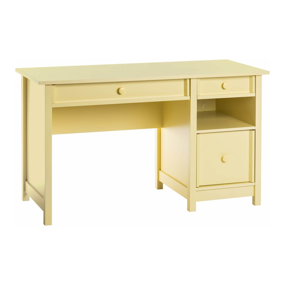
- Page 1 Teknik www.teknikoffice.co.uk Sit and surf. Computer Desk 5414142 Cobblestone Grey 5414141 Cottage Green 5414693 Sherbet Yellow NOTE: THIS INSTRUCTION BOOKLET CONTAINS IMPORTANT SAFETY INFORMATION. PLEASE READ AND KEEP FOR FUTURE REFERENCE.
- Page 2 Table of Contents Assembly Tools Required Part Identifi cation No. 2 Phillips Screwdriver Tip Shown Actual Size Hardware Identifi cation Assembly Steps 5-28 Hammer Not actual size Français 29-32 Español 33-36 Skip the power trip. Safety 37-38 This time. Warranty Part Identifi...
- Page 3 Now you know Part Identifi cation our ABCs. D113 D114 D713 D114 D113 D113 D116 D102 D112 D722 D116 D713 D102 D113 D112 Page 3...
- Page 4 Hardware Identifi cation å Screws are shown actual size. You may receive extra hardware with your unit. 40CA CABINET RIGHT - 2 40CB CABINET LEFT - 2 40CC DRAWER RIGHT - 2 40CD DRAWER LEFT - 2 (EXTENSION SET SHOWN SEPARATED) EXTENSION RAIL - 2 EXTENSION SLIDE - 2 FILE GLIDE - 2...
- Page 5 Step 1 Assemble your unit on a carpeted fl oor or on the empty carton to å avoid scratching your unit or the fl oor. Push thirty-six HIDDEN CAMS (1F) into the ENDS (A and B), å UPRIGHT (C), BOTTOMS (E), MODESTY PANEL (F) and SHELF (G).
- Page 6 Step 2 Turn eighteen CAM SCREWS (8F) into the LEGS (I and J). å Remember: Righty tighty. Lefty loosey. (18 used) Page 6...
- Page 7 Step 3 Fasten two LEFT FRONT LEGS (I) to the LEFT END (B) å and UPRIGHT (C). Tighten six HIDDEN CAMS. Fasten a RIGHT FRONT LEG (J) to the RIGHT END (A). å Tighten three HIDDEN CAMS. These edges should be even. These edges should be even.
- Page 8 Step 4 Flip the ENDS (A and B) and UPRIGHT (C) over onto their å opposite surface. Turn six BLACK 9/16" FLAT HEAD SCREWS (32S) into å the ENDS (A and B) and UPRIGHT (C) until the shoulders of the SCREWS rest on the surface of each one. Slide the LOWER END MOLDINGS (U) onto the ENDS and These edges å...
- Page 9 Step 5 Flip the ENDS (A and B) and UPRIGHT (C) over onto their å opposite surface. Fasten two RIGHT FRONT/LEFT BACK LEGS (J) to the LEFT å END (B) and UPRIGHT (C). Tighten six HIDDEN CAMS. Fasten a LEFT FRONT/RIGHT BACK LEG (I) to the RIGHT å...
- Page 10 Step 6 Separate the EXTENSION SLIDES (Z) from the EXTENSION RAILS (Y) å as shown in the upper diagram below. Be prepared, the parts are greasy. Fasten an EXTENSION RAIL (Y) to the RIGHT END (A) and UPRIGHT (C). å Use four GOLD 5/16"...
- Page 11 Step 7 Fasten a CABINET RIGHT (40CA) to the RIGHT END (A) å and a CABINET LEFT (40CB) to the UPRIGHT (C) and LEFT END (B). Use six GOLD 5/16" FLAT HEAD SCREWS (3S) through holes #1 and #3. Roller end Roller end GOLD 5/16"...
- Page 12 Step 8 Flip the UPRIGHT (C) over onto its opposite surface. å Fasten the EXTENSION BLOCK (X) to the UPRIGHT (C). å Use two BLACK 1-1/4" FLAT HEAD SCREWS (7S). Fasten the CABINET RIGHT (40CA) to the EXTENSION å BLOCK (X). Use two GOLD 5/16" FLAT HEAD SCREWS (3S) through holes #1 and #3.
- Page 13 Step 9 Fasten the MODESTY PANEL (F) to the LEFT END (B). å Tighten two HIDDEN CAMS. Now might be a good time to refresh your drink. Curved edge S u r f a c w i t h H I D D E N Caution Start...
- Page 14 Step 10 Fasten the MODESTY PANEL (F) and LEFT END (B) to the å TOP (D). Tighten four HIDDEN CAMS. Maximum Arrow 210 degrees Minimum Caution 190 degrees Do not stand the unit upright without the BACK fastened. The unit may collapse. Page 14...
- Page 15 Step 11 Fasten the UPRIGHT (C) to the TOP (D). Tighten two å HIDDEN CAMS. Maximum Arrow 210 degrees Fasten the UPRIGHT (C) to the MODESTY PANEL (F). Use å two BLACK 1-7/8" FLAT HEAD SCREWS (2S). Minimum 190 degrees BLACK 1-7/8"...
- Page 16 Step 12 Flip your unit onto its back edge with the roller end of the å CABINET RAILS up. Maximum Arrow 210 degrees Fasten the SHELF (G) to the UPRIGHT (C). Tighten two å HIDDEN CAMS. Minimum 190 degrees Roller end Finished edge S u r f a c...
- Page 17 Step 13 Insert four METAL PINS (1R) into the short edges of å the BOTTOMS (E). Maximum Arrow 210 degrees Fasten the BOTTOMS (E) to the UPRIGHT (C). Tighten å two HIDDEN CAMS. Minimum NOTE: Be sure the METAL PINS insert into the holes in 190 degrees å...
- Page 18 Step 14 Fasten the RIGHT END (A) to the TOP (D), SHELF (G), and å BOTTOMS (E). Tighten six HIDDEN CAMS. Maximum Arrow 210 degrees NOTE: Be sure the METAL PINS in the BOTTOMS insert å into the holes in the END. Minimum 190 degrees Page 18...
- Page 19 Step 15 Carefully turn your unit over onto its front edges. Lay the å Caution BACK (H) over your unit. Do not stand the unit upright without the Make equal margins along all four edges of the BACK (H). å BACK fastened.
- Page 20 Step 16 Fasten two LARGE METAL BRACKETS (19G) to the BOTTOM (E) å near the fl oor. Use two BLACK 9/16" LARGE HEAD SCREWS (1S). Don't worry. It isn't Rome. This can be built Fasten the SKIRT (T) to the LARGE METAL BRACKETS (19G). Use å...
- Page 21 Step 17 Fasten the PENCIL DRAWER MOLDING (V) to the å PENCIL DRAWER FRONT (Q). Use three BLACK 1-7/8" FLAT HEAD SCREWS (2S). Fasten the DRAWER MOLDING (W) to the SMALL å DRAWER FRONT (K). Use two BLACK 1-7/8" FLAT HEAD SCREWS (2S).
- Page 22 Step 18 1. Fasten two DRAWER SIDES (D113) to a PENCIL å DRAWER FRONT/BACK (D116). Use four BLACK 1-9/16" FLAT HEAD SCREWS (30S). 2. Slide the LARGE DRAWER BOTTOM (D722) into å the grooves of the DRAWER SIDES (D113) and PENCIL DRAWER FRONT/BACK (D116).
- Page 23 Step 19 Fasten the PENCIL DRAWER FRONT (Q) to a PENCIL å DRAWER FRONT/BACK (D116). Use four BLACK 7/8" LARGE HEAD SCREWS (17S). Fasten the KNOB (63K) to the PENCIL DRAWER FRONT (Q). å Use a BLACK 1-5/8" PAN HEAD SCREW (27S). Fasten a DRAWER RIGHT (40CC) and DRAWER LEFT (40CD) å...
- Page 24 Step 20 1. Fasten two LARGE DRAWER SIDES (D102) to a LARGE å DRAWER FRONT/BACK (D112). Use four BLACK 1-9/16" FLAT HEAD SCREWS (30S). 2. Slide the DRAWER BOTTOM (D713) into the grooves of å the LARGE DRAWER SIDES (D102) and LARGE DRAWER FRONT/BACK (D112).
- Page 25 Step 21 Fasten the LARGE DRAWER FRONT (O) to a LARGE å DRAWER FRONT/BACK (D112). Use four BLACK 7/8" LARGE HEAD SCREWS (17S). Fasten the KNOB (63K) to the LARGE DRAWER FRONT (O). å Use a BLACK 1-5/8" PAN HEAD SCREW (27S). BLACK 1-5/8"...
- Page 26 Step 22 Fasten the EXTENSION SLIDES (Z) to the LARGE å DRAWER SIDES (D102). Use four GOLD 5/16" FLAT HEAD SCREWS (3S) through holes #1 and #3. Open end D102 D102 Open end GOLD 5/16" FLAT HEAD SCREW (4 used in this step) Page 26...
- Page 27 Step 23 Push the FILE GLIDES (3B) over the top edge of the å LARGE DRAWER SIDES (D102). D102 D102 Page 27...
- Page 28 Step 24 Carefully stand your unit upright. å Push a CAM COVER (33P) onto each visible HIDDEN CAM. å To insert the large drawer into your unit, line up the EXTENSION SLIDES on the drawer with the EXTENSION RAILS on the å...
- Page 29 WARNING Please use your furniture correctly and safely. Improper use can cause safety hazards, or damage to your furniture or household items. Carefully read the following chart. Look out for: What can happen: How to avoid the problem: • Overloaded shelves and drawers. •...
Need help?
Do you have a question about the 5414142 and is the answer not in the manual?
Questions and answers