
Related Manuals for TSI Instruments VelociCalc Plus 8384


Summary of Contents for TSI Instruments VelociCalc Plus 8384
- Page 1 Model 8384/8384A/8385/ 8385A/8386/8386A ® Plus ELOCI Air Velocity Meters Operation and Service Manual March 1998 P/N 1980321...
- Page 2 Model 8384/8384A/8385/ 8385A/8386/8386A ® Plus ELOCI Air Velocity Meters Operation and Service Manual March 1998 P/N 1980321 SHIP TO: MAIL TO: TSI Incorporated TSI Incorporated 500 Cardigan Road P.O. Box 64394 Shoreview, MN 55126-3996 St. Paul, MN 55164-0394 U.S. INTERNATIONAL Sales and Customer Service: Sales and Customer Service: (800) 777-8356 / (651) 490-2711...
- Page 3 © Copyright TSI Incorporated/March 1998/All rights reserved. Address TSI Incorporated/P.O. Box 64394/St. Paul, MN 55164/USA Fax No. (612) 490-2874 LIMITATION OF WARRANTY AND LIABILITY. Seller warrants that this product, under normal use and service as described in the operator's manual, shall be free from defects in workmanship and material for a period of twenty-four (24) months, or the length of time specified in operator's manual, from the date of shipment to the customer.
-
Page 4: Table Of Contents
CONTENTS Chapters 1. UNPACKING AND PARTS IDENTIFICATION ......1 Parts Identification............... 2 2. SETTING-UP ................3 Supplying Power to the V plus ........3 ELOCI Installing the Batteries ............3 Using the Optional AC Adapter..........3 Selecting the Display Units ............3 Using The Telescoping Probe............ - Page 5 Downloading Data to a Computer ..........15 Data Acquisition (Polling) ............16 4. MAINTENANCE ................ 17 Recalibration ................17 Cases ..................17 Storage ..................17 5. TROUBLESHOOTING.............. 19 Appendices A. SPECIFICATIONS..............21 B. DIP SWITCH SETTINGS............25...
-
Page 6: Chapters
Chapter 1 Unpacking and Parts Identification Carefully unpack the instrument and accessories from the shipping container. Check the individual parts against the list of components in Table 1-1. If anything is missing or damaged, notify TSI immediately. Table 1-1: List of Components Item Description Part / Model... -
Page 7: Parts Identification
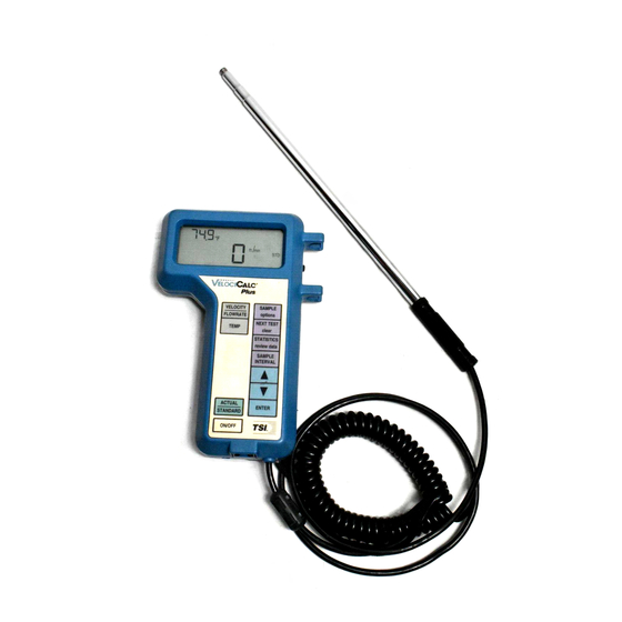
Parts Identification Figure 1-1: V Plus ELOCI 1. Backlight Switch 5. Pressure Measurement Ports 2. Display 6. Battery Access Cover 3. Keypad 7. AC Adapter port 4. Probe Mounting Clips 8. Printer Output / Communications Port Chapter 1... -
Page 8: Setting-Up
Chapter 2 Setting-up Supplying Power to the V Plus ELOCI The V Plus can be powered in one of two ways: four size AA ELOCI batteries or the optional AC adapter. Installing the Batteries Insert four AA batteries as indicated by the diagram located on the inside of the battery compartment. -
Page 9: Extending The Probe
Extending The Probe To extend the probe, hold the handle in one hand while pulling on the probe tip with the other hand. Do not hold the cable while extending the probe as this prevents the probe from moving. Retracting The Probe To retract the probe, hold the handle in one hand while pushing on the probe tip with the other hand. -
Page 10: Connecting The Optional Model 8925 Portable Printer
Connecting the Optional Model 8925 Portable Printer To connect the Model 8925 printer to the V Plus, locate the ELOCI Printer Interface Cable (supplied with the optional printer) and connect the 9-pin end labeled “PRINTER” to the printer and the other end to the data port of the V Plus. -
Page 11: Operation
Chapter 3 Operation Keypad Functions When pressing the keys on the front panel, the V Plus will beep ELOCI to confirm the function. If you press a key and the V Plus does ELOCI not beep, then the V Plus does not allow that function during the ELOCI selected mode. -
Page 12: Arrow ( ) Keys
Arrow ( ) Keys Press to scroll through choices while setting a parameter. To set the date and time, press and hold both arrow keys during the initial power up sequence when time is displayed. See Setting the Real Time Clock section in Chapter 2 for more details. -
Page 13: Pressure (Zero) Key (Models 8385/8385A/8386/8386A Only)
size of the duct, then press ENTER to accept the choice and return to measuring. • If horn is chosen: to scroll through horn numbers shown on the display (100, symbol, then press ENTER to accept the choice. 300, 600, 1200) and K NOTE: The horn numbers are the models of the horns. -
Page 14: Temperature Key
TEMPERATURE Key Press and release to display temperature on the large digits instead of showing it on the small digits. Temperature is usually displayed on the small digits when other measurement types are on the large digits. HUMIDITY Key (Model 8386/8386A Only) Press to toggle between displaying % relative humidity, dew point temperature, and wet bulb temperature on the large digits. -
Page 15: Sample (Options) Key
ENTER to accept choice and return to measuring mode. If a logging interval is chosen that is shorter than the time constant, the time constant will be shortened to be equal to the logging interval. To operate the instrument in discrete data logging (or single point) mode, the logging interval must be set to OFF. - Page 16 measurement type will automatically log if it is needed to calculate the measurement type on the large digits when the SAMPLE key is pressed. For example, if dew point is being displayed on the large display digits and SAMPLE is pressed, then dew point, humidity, and temperature will all be stored automatically because dew point is calculated using humidity and temperature.
-
Page 17: Next Test (Clear) Key
NEXT TEST (clear) Key Press to advance to the next test ID. If the current test ID does not have anything stored, it will not advance to the next test ID. To clear the last sample, press and hold the key and the display will begin a countdown from 5 to 0. -
Page 18: Heat Flow Key (Model 8386/8386A Only)
HEAT FLOW Key (Model 8386/8386A Only) In order for the V Plus to calculate heat flow, the flow rate, ELOCI temperature, and humidity need to be recorded at one location before the heating (or cooling) source and one location after the source. The data at these locations must be stored in two sequential test IDs. -
Page 19: Printing Data Using The Portable Printer
To record readings of heat flow over time, proceed as above with steps 1-12 and then follow the steps below. 1. Change from discrete to continuous data logging (See SAMPLE INTERVAL Key and SAMPLE (options) Key sections for details on how to change to continuous sampling mode). -
Page 20: Data Acquisition (Polling)
Data Acquisition (Polling) The V Plus is designed to allow the user to perform polling ELOCI through the use of a computer. To do this the user’s computer must be hooked up and in terminal mode and the baud rate for the computer and the Plus must be set to the same value. -
Page 21: Maintenance
Chapter 4 Maintenance The V Plus requires very little maintenance to keep it ELOCI performing well. Recalibration To maintain a high degree of accuracy in your measurements, we recommend that you return your V Plus to TSI for annual ELOCI recalibration. -
Page 22: Troubleshooting
Chapter 5 Troubleshooting Table 5-1 lists the symptoms, possible causes, and recommended solutions for common problems encountered with the V Plus. If your ELOCI symptom is not listed, or if none of the solutions solves your problem, please contact TSI. Table 5-1: Troubleshooting the V Plus ELOCI... - Page 23 Symptom Possible Causes Corrective Action Zero velocity is Pressure tubing is Switch the pressure hoses displayed while connected backwards on the V Plus ELOCI flow from pressure and see if problem mode has been persists selected and there Pressure sensor is broken Return to TSI for service is flow present “nO rEF”...
-
Page 24: Specifications
Appendix A Specifications Specifications are subject to change without notice. Velocity From Thermal Sensor (all models): Range: 0 to 9999 ft/min (0 to 50 m/s) 1&2 Accuracy ±3% of reading or ±3 ft/min (±0.015 m/s), whichever is greater Resolution: 1 ft/min (0.01 m/s) Velocity From a Pitot Tube (Models 8385/8385A/8386/8386A): Range 250 to 15500 ft/min (1.27 to 78.7 m/s) - Page 25 Relative Humidity (Models 8386/8386A): Range: 0 to 95%rh Accuracy : ±3% rh Resolution: 0.1% rh Wet Bulb Temperature (Models 8386/8386A) Range: 40 to 140°F (5 to 60°C) Resolution: 0.1°F (0.1°C) Dew point (Model 8386/8386A): Range: 5 to 120°F (-15 to 49°C) Resolution: 0.1°F (0.1°C) Heat Flow (Models 8386/8386A): Range:...
- Page 26 Response Time (all models): Velocity: 200 msec Temperature: 2 minutes (to 66% of final value) Pressure: 0.1 msec Humidity: < 1 minute (to 66% of final value) External Meter Dimensions (all models): 4.2 in. x 7.2 in. x 1.5 in. (10.7 cm x 18.3 cm x 3.8 cm) Meter Probe Dimensions (all models): Probe Length: 40 inches (101.6 cm)
-
Page 27: Dip Switch Settings
Appendix B DIP Switch Settings To access the DIP switched, remove the batteries from the battery compartment. On the inside of the battery compartment, there is a window with eight DIP switches (see Fig. B-1). The table below shows the functions for each switch. - Page 28 DIP SWITCH Figure B-1: DIP Switch Location Appendix B...
Need help?
Do you have a question about the VelociCalc Plus 8384 and is the answer not in the manual?
Questions and answers