
Related Manuals for TSI Instruments 9565 Series


Summary of Contents for TSI Instruments 9565 Series
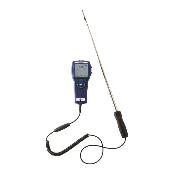
- Page 1 ENERGY AND COMFORT Ve n t ilat io n Te st in g ® ELOCI Air Velocity Meter Model 9565 Series Operation and Service Manual...
- Page 2 Copyright TSI Incorporated / 2011 / All rights reserved. Address TSI Incorporated / 500 Cardigan Road / Shoreview, MN 55126 / USA Fax No. (651) 490-3824 LIMITATION OF WARRANTY AND LIABILITY (effective July 2000) Seller warrants the goods sold hereunder, under normal use and service as described in the operator's manual, shall be free from defects in workmanship and material for twenty-four (24) months, or the length of time specified in the operator's manual, from the date of shipment to the customer.
-
Page 3: Table Of Contents
CONTENTS CHAPTER 1 UNPACKING AND PARTS IDENTIFICATION ..... 1 CHAPTER 2 SETTING-UP ..............3 Supplying Power to the Model 9565 Series ........3 Installing the Batteries ............... 3 DIP Switch Settings ..............3 Do not attempt to charge alkaline batteries....... 4 Using the AC Adapter .............. - Page 4 Print Test .................. 26 Delete Data ................26 % Memory ................28 ZERO CO ..................28 APPLICATIONS ................. 29 CALIBRATION .................. 30 DISCOVER BLUETOOTH ..............30 Printing Data Using the Portable Printer ........31 ™ Data Analysis Software ..........31 LogDat2™...
-
Page 5: Chapter 1 Unpacking And Parts Identification
Chapter 1 Unpacking and Parts Identification Carefully unpack the instrument and accessories from the shipping container. Check the individual parts against the list of components below. If anything is missing or damaged, notify TSI immediately. 1. Carrying case 2. Instrument 3. - Page 6 (This page intentionally left blank) Chapter 1...
-
Page 7: Chapter 2 Setting-Up
Chapter 2 Setting-up Supplying Power to the Model 9565 Series ® The Model 9565 V Air Velocity Meter can be powered in one of ELOCI two ways: four size AA batteries or the AC adapter. Installing the Batteries Insert four AA batteries as indicated by the diagram located on the inside of the battery compartment. -
Page 8: Do Not Attempt To Charge Alkaline Batteries
Do not attempt to charge alkaline batteries. Using the AC Adapter The AC adapter can be used to power the instrument or to charge the NiMH batteries when the DIP switch in the battery compartment is set to NiMH. If the DIP switch is set to Alkaline, and the AC power adapter is connected, then the batteries will be bypassed and the meter will be powered by the AC adapter. -
Page 9: Using The Telescoping Thermoanemometer Probes
Using the Telescoping Thermoanemometer Probes The telescoping probe contains the velocity, temperature, and humidity sensors. When using the probe, make sure the sensor window is fully exposed and the orientation dimple is facing upstream. NOTE: For temperature and humidity measurements, make sure that at least 3 inches (7.5 cm) of the probe is in the flow to allow the temperature and humidity sensors to be in the air stream. -
Page 10: Connecting The Static Pressure Probe
Connecting the Static Pressure Probe The Static Pressure probe included with the 9565-P is connected to the + port on the 9565-P using the included tubing. The Static Pressure probe is used to measure the duct static pressure and features a magnet which holds the probe to the ductwork. -
Page 11: Do Not Use The Instrument Or Probes Near Hazardous Voltage Sources Since Serious Injury Could Result
Total pressure hole Static pressure holes Static pressure port (to – input on manometer) Total pressure port (to + input on manometer) Do not use the instrument or probes near hazardous voltage sources since serious injury could result. Setting-up... -
Page 12: Thermocouple Ports
Thermocouple Ports The 9565 series includes two thermocouple ports at the base of the meter. Any K-Alloy thermocouple with mini-connector can be attached. See Display Setup for setting the thermocouple temperature readings to be displayed as TC1, TC2, or TC1-TC2. -
Page 13: Connecting The Optional Bluetooth Portable Printer Device
® Connecting the Optional Bluetooth Portable Printer Device To connect the Bluetooth printer to the Model 9565, power on the unit and the printer. Then press the MENU soft key. From the Menu use the keys to highlight Discover Bluetooth and press the key. - Page 14 (This page intentionally left blank) Chapter 2...
-
Page 15: Chapter 3 Operation
Chapter 3 Operation Battery Indicator Pressure Ports Activity Area Additional Messages Primary Soft Key Indicators Parameter Secondary Parameters Soft Keys Keypad Functions Press the ON/OFF key to turn the Model 9565 on ON/OFF ( ) Key and off. During the power up sequence the display will show the following: Model Number, Serial Number, and Software Revision. -
Page 16: Common Terms
Arrow (or ) and Press arrow keys to change choices while setting a Menu Soft Keys parameter. Press the Menu soft key to select the Menu selections, which are Pressure Zero, Display Setup, Settings, Flow Setup, VOC Setup, Actual/Std Setup, Data Logging, Zero CO, Applications, Calibration, and Discover Bluetooth. -
Page 17: Menus
Menus The menu structure is organized to allow easy navigation and instrument setup utilizing the arrow keys and button. To exit a menu or menu item, press the ESC key. To access the Menu items, press the Menu soft key. •... -
Page 18: Settings
MENU DISPLAY SETUP Zero Press Velocity Display Setup Flow Settings Pitot Velocity Flow Setup Pressure VOC Setup Temperature Actual/Std Setup Baro Press Data Logging AFProbe Velocity ON Zero CO Applications Calibration Discover Bluetooth PRIMARY NOTE: Pitot Velocity and AFProbe Velocity cannot both be ON at the same time, nor can one be set to PRIMARY and the other to ON. -
Page 19: Voc Setup
NOTE: Press/Kfact allows for calculating flow rate from diffusers or flow stations with pressure taps using the instruments pressure ports and Kfactors. The Kfactors are obtained from the diffuser or flow station manufacturer. For more information, refer to Application Note TSI-114. -
Page 20: Actual/Standard Setup
MENU VOC SETUP Zero Press Response Factor 1.00 Display Setup Mole Weight 56.11 Settings Reset Isobutylene Flow Setup RESET ISOBUTYLENE VOC Setup Actual/Std Setup Data Logging Reset Isobutylene Zero CO Applications Calibration Discover Bluetooth ACTUAL/STANDARD SETUP Choose Actual/Standard measurements and parameters in the Act/Std Setup menu. -
Page 21: Data Logging
DATA LOGGING Measurements Measurements to be logged to memory are independent of measurements on the display, and must therefore be selected under DATA LOGGING Measurements. When set to ON, measurement will be logged to memory. • When set to DISPLAY, measurement will be logged to memory if it •... - Page 22 Manual Logging Manual mode does not automatically save data, but instead prompts the user to SAVE a sample or ESC to not save. To start logging, press the key. NOTE: To adjust the averaging period for a sample, change the Time Constant (increase or decrease in seconds) which is located in the Settings Menu.
- Page 23 When set to Auto-save, the Sample Time can be adjusted. Sample Time is the time period over which the Sample will be averaged. DATA LOGGING SAMPLE TIME Measurements Log Mode Auto-save Log Settings 00:05 Choose Test Test 001 Min:Sec Name Test View Data Delete Data % Memory...
- Page 24 When set to Cont. key, the log interval can be adjusted. DATA LOGGING LOG SETTINGS Measurements LOG INTERVAL Log Mode Cont.-key Log Interval 00:01 Log Settings 00:05 Min:Sec Choose Test Test 001 Name Test View Data Delete Data % Memory ...
- Page 25 When set to Cont.-time, the log interval and test length can be adjusted. DATA LOGGING LOG SETTINGS LOG INTERVAL Measurements Log Mode Cont.-time Log Interval 00:01 Log Settings 00:05 Test Length 00:00:01 Min:Sec Choose Test Test 001 Name Test View Data TEST LENGTH Delete Data % Memory...
-
Page 26: Choose Test
For more information, refer to the T Data Analysis Software User’s Guide which can be found on the T software CD which is included with the 9565. Choose Test Test ID’s consist of a group of Samples that are used to determine statistics (average, minimum, and maximum) of a measurement application. -
Page 27: Name Test
DATA LOGGING CHOOSE TEST Measurements Test 001 9 Samples Log Mode Cont.-time Test 002 7 Samples Log Settings Test 003 0 Samples Choose Test Test 001 Test 004 0 Samples Name Test Test 005 0 Samples View Data Test 006 0 Samples Delete Data Test 007... -
Page 28: View Data
View Data Choose Test To view stored data, first select the Test ID that contains the data to be recalled. This is accomplished in the “Choose Test” menu. DATA LOGGING VIEW DATA Measurements CHOOSE TEST Choose Test Test 001 Log Mode Auto-save Test 001 9 Samples... -
Page 29: View Samples
TEST 001 TEST 001 TEST 001 Pressure Temperature 1.739 in. H2O 78.2 ˚F 12.2 %RH 1.665 in. H2O 78.1 ˚F 11.1 %RH 1.812 in. H2O 78.3 ˚F 12.9 %RH # Samples # Samples # Samples 10/31/08 07:01:39 AM 10/31/08 07:01:39 AM 10/31/08 07:01:39 AM PRINT PRINT... -
Page 30: Print Test
TEST 001 TEST 001 TEST 001 Velocity Temperature Sample 1 218 ft/min Sample 1 73.5 ˚F Sample 1 15.1%rh Sample 2 280 ft/min Sample 2 73.7 ˚F Sample 2 14.2%rh Sample 3 316 ft/min Sample 3 73.8 ˚F Sample 3 13.8%rh Sample 4 399 ft/min... - Page 31 DATA LOGGING DELETE DATA Measurements Delete All Log Mode Cont.-time Delete Test Log Settings Delete Sample Choose Test Test 001 Name Test View Data Delete Data % Memory Delete All will clear stored data in all Test ID’s. DELETE DATA DELETE ALL Delete All Delete Test...
-
Page 32: Zero Co
DELETE DATA DELETE SAMPLE Delete All Test 001 14 Samples Delete Test Test 002 10 Samples Delete Sample Test 003 12 Samples Test 004 8 Samples Test 005 7 Samples Test 006 15 Samples Test 007 0 Samples Test 008 0 Samples Test 009 0 Samples... -
Page 33: Applications
MENU ZERO CO Zero Press Display Setup Settings Flow Setup 0.0 ppm VOC Setup Actual/Std Setup Data Logging Zero CO Applications Calibration Discover Bluetooth NOTE: The Zero CO function should be performed in an area where no combustion is taking place which may affect zeroing of the sensor. APPLICATIONS This menu option includes specialized measurement protocols used to perform various tests or investigations. -
Page 34: Calibration
CALIBRATION The Calibration Menu lists measurement parameters that can be adjusted in the field. The appropriate detachable probes must be attached to the 9565 before field calibration can be undertaken except for pressure and barometric pressure calibration. For more information on performing field calibrations, refer to TSI Applications Note TSI-146. -
Page 35: Printing Data Using The Portable Printer
Printing Data Using the Portable Printer To print logged data, first enter the DATALOGGING menu. Then, use the CHOOSE TEST item to select the data to be printed. After the test is selected, use the VIEW STATS and VIEW SAMPLES items to select statistics or individual data points to view and print. - Page 36 (This page intentionally left blank) Chapter 3...
-
Page 37: Chapter 4 Maintenance
Chapter 4 Maintenance The Model 9565 requires very little maintenance to keep it performing well. Recalibration To maintain a high degree of accuracy in your measurements, we recommend that you return your Model 9565 to TSI for annual recalibration. Please contact one of TSI’s offices or your local distributor to make service arrangements and to receive a Return Material Authorization (RMA) number. - Page 38 (This page intentionally left blank) Chapter 4...
-
Page 39: Chapter 5 Troubleshooting
Chapter 5 Troubleshooting Table 5-1 lists the symptoms, possible causes, and recommended solutions for common problems encountered with the Model 9565. If your symptom is not listed, or if none of the solutions solves your problem, please contact TSI. Table 5-1: Troubleshooting the Model 9565 Symptom Possible Causes Corrective Action... - Page 40 (This page intentionally left blank) Chapter 5...
-
Page 41: Appendix A Specifications
Appendix A Specifications Specifications are subject to change without notice. Velocity (TA Probe): Range: 0 to 9999 ft/min (0 to 50 m/s) 1&2 Accuracy ±3% of reading or ±3 ft/min (±0.015 m/s), whichever is greater Resolution: 1 ft/min (0.01 m/s) Velocity (Pitot Tube): Range 250 to 15500 ft/min (1.27 to 78.7 m/s) - Page 42 Static / Differential Pressure: Range -15 to +15 in. H O (-28.0 to +28.0 mm Hg, -3735 to +3735 Pa) Accuracy: ±1% of reading ±0.005 in. H O (±1 Pa, ±0.01 mm Hg) Resolution: 0.001 in. H O (0.1 Pa, 0.01 mm Hg) Barometric Pressure: Range: 20.36 to 36.648 in.
-
Page 43: Power Requirements
Power Requirements: Four AA-size batteries (included) or AC Adapter p/n 801761 Input: 90 to 240 VAC, 50 to 60 Hz Output: 9 VDC, 2A Temperature compensated over an air temperature range of 40 to 150°F (5 to 65°C). The accuracy statement of ±3.0% of reading or ±3 ft/min (±0.015 m/s), whichever is greater, begins at 30 ft/min through 9999 ft/min (0.15 m/s through 50 m/s). - Page 44 (This page intentionally left blank) Appendix A...
-
Page 45: Appendix B Optional Plug-In Probes
Appendix B Optional Plug-in Probes Thermoanemometer Probes Model Description Air Velocity and Temperature, Straight Probe Air Velocity and Temperature, Articulating Probe Air Velocity, Temperature, and Humidity, Straight Probe Air Velocity, Temperature, and Humidity, Articulating Probe Rotating Vane Anemometer Probes Model Description 4 in. - Page 46 Pitot Probes Model Description 634634000 Pitot Probe 12" (30 cm) - 5/16" (8 mm) diameter 634634001 Pitot Probe 18" (46 cm) - 5/16" (8 mm) diameter 634634002 Pitot Probe 24" (61 cm) - 5/16" (8 mm) diameter 634634003 Pitot Probe 36" (91 cm) - 5/16" (8 mm) diameter 634634005 Pitot Probe 60"...
- Page 47 TSI Incorporated – 500 Cardigan Road, Shoreview, MN 55126 U.S.A Tel: +1 800 874 2811 E-mail: info@tsi.com Website: www.tsi.com Tel: +44 149 4 459200 E-mail: Website: tsiuk@tsi.com www.tsiinc.co.uk France Tel: +33 491 11 87 64 E-mail: tsifrance@tsi.com Website: www.tsiinc.fr Germany Tel: +49 241 523030 E-mail: tsigmbh@tsi.com Website:...
Need help?
Do you have a question about the 9565 Series and is the answer not in the manual?
Questions and answers