
Related Manuals for TSI Instruments Q-TRAK 7575


Summary of Contents for TSI Instruments Q-TRAK 7575
- Page 1 Q-TRAK™ INDOOR AIR QUALITY MONITOR MODEL 7575 OPERATION AND SERVICE MANUAL P/N 6004850, REVISION G JUNE 2018...
- Page 3 Copyright TSI Incorporated / 2011-2018 / All rights reserved. Address TSI Incorporated / 500 Cardigan Road / Shoreview, MN 55126 / USA Fax No. (651) 490-3824 Limitation Of Warranty And Liability (effective February 2016) (For country-specific terms and conditions outside of the USA, please visit www.tsi.com.) Seller warrants the goods, excluding software, sold hereunder, under normal use and service as described in the operator's manual, to be free from defects in workmanship and material for 24 months, or if less, the length of time specified in the operator's...
- Page 4 INJURIES, OR DAMAGES CONCERNING THE GOODS (INCLUDING CLAIMS BASED ON CONTRACT, NEGLIGENCE, TORT, STRICT LIABILITY OR OTHERWISE) SHALL BE THE RETURN OF GOODS TO SELLER AND THE REFUND OF THE PURCHASE PRICE, OR, AT THE OPTION OF SELLER, THE REPAIR OR REPLACEMENT OF THE GOODS. IN THE CASE OF SOFTWARE, SELLER WILL REPAIR OR REPLACE DEFECTIVE SOFTWARE OR IF UNABLE TO DO SO, WILL REFUND THE PURCHASE PRICE OF THE SOFTWARE.
-
Page 5: Table Of Contents
CONTENTS CHAPTER 1 UNPACKING AND PARTS IDENTIFICATION ..... 1 CHAPTER 2 SETTING-UP ..............3 Supplying Power to the Model 7575 Q-Trak IAQ Monitor ....3 Installing the Batteries ............... 3 DIP Switch Settings ..............3 Using the AC Adapter ..............4 Connecting IAQ or Ventilation Probes .......... - Page 6 BLUETOOTH FUNCTIONS ..............32 Discover Devices ..............33 Discoverability ................33 PINcode ................... 33 # AutoConnects ............... 33 Printing Data Using the Portable Printer ........33 TrakPro™ Data Analysis Software ..........34 CHAPTER 4 MAINTENANCE ............35 Recalibration ................. 35 Cases ....................
-
Page 7: Chapter 1 Unpacking And Parts Identification
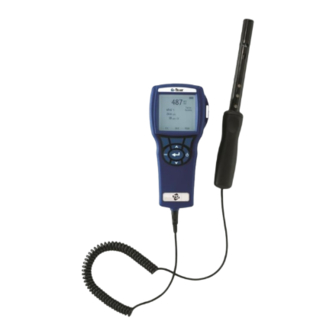
Chapter 1 Unpacking and Parts Identification Carefully unpack the instrument and accessories from the shipping container. Check the individual parts against the list of components below. If anything is missing or damaged, notify TSI immediately. 1. Carrying case 2. Instrument (7575-X or 7575-X-NB) 3. - Page 8 NO T E This equipment has been tested and found to comply with the limits for a Class B digital device, pursuant to part 15 of the FCC Rules (FCC ID: PI4411B). These limits are designed to provide reasonable protection against harmful interference in a residential installation.
-
Page 9: Chapter 2 Setting-Up
Chapter 2 Setting-up ™ Supplying Power to the Model 7575 Q-Trak IAQ Monitor The Model 7575 Q-Trak Indoor Air Quality (IAQ) Monitor can be powered in one of two ways: four size AA batteries or the AC adapter. Installing the Batteries Insert four AA batteries as indicated by the diagram located on the inside of the battery compartment. -
Page 10: Using The Ac Adapter
DO NOT attempt to charge alkaline batteries. Using the AC Adapter The AC adapter can be used to power the instrument or to charge the NiMH batteries when the DIP switch in the battery compartment is set to NiMH. If the DIP switch is set to Alkaline, and the AC power adapter is connected, then the batteries will be bypassed and the monitor will be powered by the AC adapter. -
Page 11: Using Optional Telescoping Thermoanemometer Probes
“D” Shaped mini-DIN connector Using Optional Telescoping Thermoanemometer Probes The telescoping probe contains the velocity, temperature, and humidity sensors. When using the probe, make sure the sensor window is fully exposed and the orientation dimple is facing upstream. N O T E For temperature and humidity measurements, make sure that at least 3 inches (7.5 cm) of the probe is in the flow to allow the temperature and humidity sensors to be in the air stream. -
Page 12: Connecting The Thermocouples
Connecting the Thermocouples The K-Alloy thermocouple with mini-connector has one terminal wider than the other. The wider terminal will be inserted into the bottom of the TC1 or TC2 connector port. K-alloy Thermocouple Thermocouples from an alternate TSI supplier must have the metal sheath electrically isolated from the wires inside. -
Page 13: Connecting The Optional Bluetooth Portable Printer Device
® Connecting the Optional Bluetooth Portable Printer Device (Model 7575-X only) To connect the Bluetooth printer to the Model 7575, power on the unit and the printer. Then press the MENU soft key. From the Menu use keys to highlight Bluetooth Functions and press the ... - Page 14 (This page intentionally left blank) Chapter 2...
-
Page 15: Chapter 3 Operation
Chapter 3 Operation Keypad Functions Press the ON/OFF key to turn the Model 7575 on ON/OFF ( ) Key and off. During the power up sequence the display will show the following: Model Number, Serial Number, and Software Revision. To turn the instrument off, press and hold the ON/OFF Key for 3 seconds. -
Page 16: Common Terms
Arrow (or ) and Press arrow keys to change choices while setting a Menu Soft Keys parameter. Press the Menu soft key to select the Menu selections, which are Display Setup, Settings, Flow Setup, VOC Setup, Actual/Std Setup, Data Logging, Zero CO, Applications, Calibration, and Bluetooth Functions. -
Page 17: Menus
Menus The menu structure is organized to allow easy navigation and instrument setup utilizing the arrow keys and button. To exit a menu or menu item, press the ESC key. To access the Menu items, press the Menu soft key. ... -
Page 18: Display Setup
DISPLAY SETUP Display Setup menu is where you will setup the desired parameters to be displayed on the instrument screen. With a parameter highlighted you can then use the ON soft key to have it show up on the instrument screen or select the OFF soft key to turn off the parameter. -
Page 19: Settings
SETTINGS Settings menu is where you can set the general settings. These include Language, Beeper, Select Units, Time Constant, Contrast, Set Time, Set Date, Time Format, Date Format, Number Format, Backlight, and Auto Off. Use the or keys to select an option, and the ... - Page 20 Round duct, Rect duct and Duct area are used to perform a duct traverse using a thermoanemometer probe. For more information on how to perform a duct traverse, refer to Application Note TSI-106. Up to 5 rectangular ducts, 5 round ducts, and 5 duct areas can be pre-programed for quick use on a jobsite: When Flow is set as the Primary measurement in the Display Setup menu, the duct dimensions will also be displayed:...
-
Page 21: Voc Setup
Make adjustments with the or arrow keys and press accept, or enter the Select Duct menu to choose a different pre- programmed dimension. N O T E S The horn numbers are the models of the horns. For example, 100 refers to a horn model number AM 100. -
Page 22: Actual/Standard Setup
ACTUAL/STANDARD SETUP Choose Actual/Standard measurements and parameters in the Act/Std Setup menu. The Model 7575 measures the actual barometric pressure using an internal sensor. The temperature source can be entered manually or taken from a probe that measures temperature (plug in probe or thermocouple). For more information on Actual and Standard conditions, refer to Application Note TSI-109. -
Page 23: Data Logging
DATA LOGGING Measurements Measurements to be logged to memory are independent of measurements on the display, and must therefore be selected under DATA LOGGING Measurements. When set to ON, measurement will be logged to memory. When set to DISPLAY, measurement will be logged to memory if it is visible on the main running screen. -
Page 24: Log Mode
Manual Logging Manual mode does not automatically save data, but instead prompts the user to SAVE a sample or ESC to not save. To start logging, press the key. N O T E To adjust the averaging period for a sample when using Manual logging, change the Time Constant (increase or decrease in seconds) which is located in the Settings Menu. -
Page 25: Sample Time
When set to Auto-save, the Sample Time can be adjusted. Sample Time is the time period over which the Sample will be averaged. DATA LOGGING SAMPLE TIME Measurements Log Mode Auto-save Log Settings 00:05 Choose Test Test 001 Min:Sec Name Test View Data Delete Data % Memory... -
Page 26: Log Settings
When set to Cont. key, the log interval can be adjusted. DATA LOGGING LOG SETTINGS Measurements LOG INTERVAL Log Mode Cont.-key Log Interval 00:01 Log Settings 00:05 Min:Sec Choose Test Test 001 Name Test View Data Delete Data % Memory N O T E Pressing the ... - Page 27 When set to Cont.-time, the log interval and test length can be adjusted. DATA LOGGING LOG SETTINGS LOG INTERVAL Measurements Log Mode Cont.-time Log Interval 00:01 Log Settings 00:05 Test Length 00:00:01 Min:Sec Choose Test Test 001 Name Test View Data TEST LENGTH Delete Data % Memory...
- Page 28 For more information, refer to the TrakPro Data Analysis Software User’s Guide which can be found on the TrakPro software CD which is included with the 7575. Chapter 3...
-
Page 29: Choose Test
Choose Test Test IDs consist of a group of Samples that are used to determine statistics (average, minimum, and maximum) of a measurement application. The 7575 can store 26,500+ samples and 100 test IDs (one sample can contain fourteen measurement types). Example: Each duct traverse will have its own Test ID consisting of several Samples. -
Page 30: View Data
View Data Choose Test To view stored data, first select the Test ID that contains the data to be recalled. This is accomplished in the “Choose Test” menu. DATA LOGGING VIEW DATA Measurements CHOOSE TEST Choose Test Test 001 Log Mode Auto-save View Stats Test 001... - Page 31 Use the arrow keys to view statistics of all the measurement parameters stored in a Test ID. TEST 001 TEST 001 TEST 001 Temperature 750 ppm 78.2 F 12.2 %RH 747 ppm 78.1 F 11.1 %RH 752 ppm 78.3 F 12.9 %RH # Samples...
-
Page 32: View Samples
View Samples VIEW DATA Choose Test Test 001 View Stats View Samples Print Test Use the arrow keys to view samples of all the measurement parameters stored in a Test ID. TEST 001 TEST 001 TEST 001 Velocity Temperature Sample 1 218 ft/min... -
Page 33: Print Test
Print Test Press to print all statistics and samples for the selected Test ID. VIEW DATA Choose Test Test 001 View Stats View Samples Print Test The 7575-X can send this data to the optional Model 8934 wireless printer or PC capable of Bluetooth communications. To use the PRINT command, Bluetooth communications must be established between the 7575-X and the Model 8934 wireless printer or PC set up with Bluetooth communications. -
Page 34: Delete Data
Delete Data Use this to delete all data, delete test or delete sample. DATA LOGGING DELETE DATA Measurements Delete All Log Mode Cont.-time Delete Test Log Settings Delete Sample Choose Test Test 001 Name Test View Data Delete Data % Memory Delete All will clear stored data in all Test ID’s. -
Page 35: Memory
Delete Sample will clear the last sample in an individual Test ID selected by the user. DELETE DATA DELETE SAMPLE Delete All Test 001 14 Samples Delete Test Test 002 10 Samples Delete Sample Test 003 12 Samples Test 004 8 Samples Test 005 7 Samples... -
Page 36: Zero Co
ZERO CO This menu item applies to TSI probe Model 982 which can measure carbon monoxide (CO). Turn the instrument on for a minimum of five minutes to let it warm up before zeroing the CO sensor. Zero CO will zero the CO sensor readings that may have drifted. -
Page 37: Applications
APPLICATIONS This menu option includes specialized measurement protocols used to perform various tests or investigations. You can choose Draft Rate, Heat flow, Turbulence, and % Outside Air in the Applications menu. For more information on these applications, refer to the following information: ... -
Page 38: Calibration
CALIBRATION The Calibration Menu lists measurement parameters that can be adjusted in the field. The appropriate detachable probes must be attached to the 7575 before field calibration can be undertaken except for pressure and barometric pressure calibration. For more information on performing field calibrations, refer to TSI Applications Note TSI-146. -
Page 39: Discover Devices
Discover Devices Start the Bluetooth process of finding other devices from the Q-Trak Model 7575-X. Discoverability Describes whether another device can discover the Q-Trak Model 7575-X. Options include: The instrument is not discoverable by other Disable devices. Allows the instrument to be discoverable until Temporary another device pairs with it or until the instrument power is turned off and back on. -
Page 40: Trakpro™ Data Analysis Software
TrakPro™ Data Analysis Software The Q-Trak Model 7575 comes with special software called T Data Analysis Software, which is designed to provide you with maximum flexibility and power. Follow the instructions on the label of the TrakPro software to install the software on your computer. -
Page 41: Chapter 4 Maintenance
Chapter 4 Maintenance The Model 7575 and probe accessories require very little maintenance to keep it performing well. Recalibration To maintain a high degree of accuracy in your measurements, we recommend that you return your Model 7575, 960 series thermoanemometer probes, IAQ and VOC probes to TSI for annual recalibration. - Page 42 (This page intentionally left blank) Chapter 4...
-
Page 43: Chapter 5 Troubleshooting
Chapter 5 Troubleshooting Table 5-1 lists the symptoms, possible causes, and recommended solutions for common problems encountered with the Model 7575. If your symptom is not listed, or if none of the solutions solves your problem, please contact TSI. Table 5-1: Troubleshooting the Model 7575 Symptom Possible Causes Corrective Action... - Page 44 (This page intentionally left blank) Chapter 5...
-
Page 45: Appendix A Specifications
Appendix A Specifications Specifications are subject to change without notice. Range: 0 to 5000 ppm Accuracy ±3% of reading or ±50 ppm, whichever is greater Resolution: 1 ppm Sensor type: Non-Dispersive Infrared (NDIR) Temperature: Range: 32 to 140F (0 to 60C) Accuracy: ±1.0F (±0.5C) Resolution:... - Page 46 Instrument Temperature Range: Operating (Electronics): 40 to 113°F (5 to 45°C) Storage: -4 to 146°F (-20 to 60°C) Instrument Operating Conditions: Altitude up to 4000 meters Relative humidity up to 80% RH, non-condensing Pollution degree 1 in accordance with IEC 664 Transient over voltage category II Data Storage Capabilities: Range:...
-
Page 47: Appendix B Optional Plug-In Probes
Appendix B Optional Plug-in Probes Thermoanemometer Probes Model Description Air Velocity and Temperature, Straight Probe Air Velocity and Temperature, Articulating Probe Air Velocity, Temperature, and Humidity, Straight Probe Air Velocity, Temperature, and Humidity, Articulating Probe Rotating Vane Anemometer Probes Model Description 4 in. - Page 48 (This page intentionally left blank) Appendix B...
- Page 49 TSI Incorporated – Visit our website www.tsi.com for more information. Tel: +1 800 874 2811 India Tel: +91 80 67877200 Tel: +44 149 4 459200 China Tel: +86 10 8219 7688 France Tel: +33 1 41 19 21 99 Singapore Tel: +65 6595 6388 Germany Tel: +49 241 523030 P/N 6004850 Rev G ©2018 TSI Incorporated...
Need help?
Do you have a question about the Q-TRAK 7575 and is the answer not in the manual?
Questions and answers