
Related Manuals for TSI Instruments P-TRAK Ultrafine


Summary of Contents for TSI Instruments P-TRAK Ultrafine
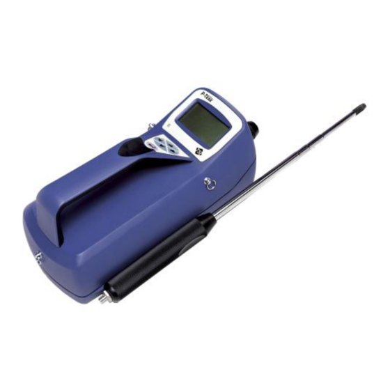
- Page 1 P-TRAK ULTRAFINE ® PARTICLE COUNTER MODEL 8525 OPERATION AND SERVICE MANUAL (TRAKPRO™ DATA ANALYSIS SOFTWARE ENCLOSED) P/N 1980380, REVISION M JULY 2013...
- Page 2 P-TRAK ULTRAFINE ® PARTICLE COUNTER MODEL 8525 OPERATION AND SERVICE MANUAL (TRAKPRO™ DATA ANALYSIS SOFTWARE ENCLOSED) P/N 1980380, REVISION M JULY 2013 SHIP TO/MAIL TO: E-mail address: TSI Incorporated answers@tsi.com 500 Cardigan Road Shoreview, MN 55126-3996 Website: http://www.tsi.com U.S. INTERNATIONAL Technical Support: Technical Support: (800) 874-2811/(651) 490-2811...
- Page 3 Copyright © TSI Incorporated / 1999–2013 / All rights reserved. Address TSI Incorporated / 500 Cardigan Road / Shoreview, MN 55126 / USA Fax No. (651) 490-3824 LIMITATION OF WARRANTY AND LIABILITY (effective June 2011) (For country-specific terms and conditions outside of the USA, please visit www.tsi.com.) Seller warrants the goods sold hereunder, under normal use and service as described in the operator's manual, shall be free from defects in workmanship and material for 24 months, or if less, the length of time specified in the operator's manual, from the date of...
- Page 4 Buyer and all users are deemed to have accepted this LIMITATION OF WARRANTY AND LIABILITY, which contains the complete and exclusive limited warranty of Seller. This LIMITATION OF WARRANTY AND LIABILITY may not be amended, modified or its terms waived, except by writing signed by an Officer of Seller. Service Policy Knowing that inoperative or defective instruments are as detrimental to TSI as they are to our customers, our service policy is designed to give prompt attention to any...
- Page 5 (This page intentionally left blank)
-
Page 6: Table Of Contents
CONTENTS SAFETY INFORMATION ..............VII UNPACKING AND PARTS IDENTIFICATION ......1 ® Unpacking the P-Trak Ultrafine Particle Counter ......1 Optional Accessories ..............4 Spare/Replacement Parts ............. 5 SETTING UP ................. 7 ® Supplying Power to the P-Trak Particle Counter ......7 Installing the Batteries .............. - Page 7 LOG MODE ................31 Log Mode 2 and 3 ................ 32 Sample Protocol for Log Mode 2 or 3 .......... 35 Memory Considerations ............... 38 Particle Sampling Configurations ..........38 Sampling Through Inlet Screen, Tube, and Probe Assembly .. 39 Sampling Through Inlet Screen and Sample Tube ....
-
Page 8: Safety Information
Safety Information When operated according to the manufacturer’s instruction, this device is a Class I laser product as defined by U.S. Department of Health and Human Services standards under the Radiation Control for Health and Safety Act of 1968. A certification and identification label like the one shown below is affixed to each instrument. - Page 9 (This page intentionally left blank) viii Safety Information...
-
Page 10: Unpacking And Parts Identification
Use the tables and illustrations below to make certain that there are no missing components. Contact TSI immediately if anything is missing or damaged. Table 1-1 Model 8525 P-Trak Ultrafine Particle Counter With Inlet Probe Assembly, Battery Pack, and Batteries Qty. Item Description... - Page 11 Table 1-2 Alcohol Fill Capsule with Storage Cap, Alcohol Cartridge, Alcohol Bottles and Shoulder Strap Qty. Item Description Part/Model Reference Alcohol fill capsule and 1083070 storage cap. Alcohol cartridge 801624 30 ml alcohol bottles 2918011 (1 shown) Chapter 1...
- Page 12 Table 1-3 Mesh Storage Bag with Spare Wicks, Computer Cable, Zero Filters, and DB9/DB25 Adapter Qty. Item Description Part/Model Reference Mesh bag Spare wick kit Computer cable, 800563 RJ45/DB9 HEPA zero filter, 801625 with adapter USB to RS-232 1102138 Converter Unpacking and Parts Identification...
-
Page 13: Optional Accessories
Table 1-4 Calibration Certificate, Operation and Service Manual, TrakPro Software Qty. Item Description Part/Model Reference Calibration Certificate Operation and Service 1980380 Manual TrakPro Software 1090014 Optional Accessories The following table lists optional accessories available for the P-Trak Ultrafine Particle Counter. Quantity Item Description AC adapter for P-Trak particle counter... -
Page 14: Spare/Replacement Parts
Spare/Replacement Parts The following items may be purchased as spare or replacement parts. Item Description Part Number Alcohol wicks with screens (Pkg. of 10) 8023 Tubing, sample, 4’ x ”, Tygon 801615 Inlet screen assembly 801616 Alcohol, 16 qty., 30 ml bottles 2918011 Unpacking and Parts Identification... - Page 15 (This page intentionally left blank) Chapter 1...
-
Page 16: Setting Up
Supplying Power to the P-Trak Particle Counter The Model 8525 P-Trak Ultrafine Particle Counter may be powered in one of two ways. The standard configuration instrument is sold with a battery holder containing 6, AA alkaline batteries. An optional AC adapter may also be used to power the instrument when operating in a fixed location. -
Page 17: Using The Ac Adapter
Figure 2-2: The Back of the Instrument 1. On/Off switch 4. AC Adapter socket 2. Inlet quick-connect fitting 5. Headphone jack 3. Communications port 6. Alcohol cartridge Using the AC Adapter The AC adapter allows you to power the P-Trak particle counter from an AC wall outlet. -
Page 18: Charging And Installing The Alcohol Wick
The CO sensor in some models of TSI IAQ monitors may be adversely affected when exposed to isopropyl alcohol vapors released from TSI instruments utilizing condensation particle counting (CPC) technology. For maximum performance, keep CO sensors away from CPC-based instruments utilizing isopropyl alcohol. -
Page 19: Locating And Identifying Components
Locating and Identifying Components To add alcohol to the P-Trak particle counter, first identify and locate the alcohol related components and accessories that are included with the instrument (refer to Table 1-2, for more information). You will need the following items: ... - Page 20 3. Open a bottle of alcohol. Invert the bottle and insert the nozzle end into the alcohol fill capsule as far as possible to make certain that you cannot inadvertently spray alcohol anywhere except down into the capsule. Fill Line Figure 2-4: Alcohol Fill Capsule 4.
-
Page 21: Installing The Cartridge Into The P-Trak Particle Counter
6. Set the alcohol fill capsule down and wait a few minutes while the wick inside the cartridge soaks up alcohol. Installing the Cartridge into the P-Trak Particle Counter 1. Remove the alcohol cartridge from the fill capsule and gently shake it to allow excess alcohol to drain back into the capsule. -
Page 22: Cleaning Up And Final Cautions
Attaching the Inlet Screen Assembly, Sample Tube, and Telescoping Probe to the Instrument The normal sampling configuration for the P-Trak Ultrafine Particle Counter consists of the inlet screen assembly, sample tube, and telescoping probe (see Chapter 3, “Operation,” for information on other sampling options). - Page 23 2. Insert the inlet screen assembly into the fitting and press it firmly until it snaps into place (see Figure 2-7). It may help to rotate the inlet screen while inserting. 3. Attach one end of the sample tube to the inlet screen assembly barbed fitting.
-
Page 24: Instrument Software And Communications Setup
Figure 2-8: Slide Telescoping Probe onto Instrument Case The P-Trak particle counter is now ready to operate. Refer to Chapter 3, “Operation,” for information on starting and operating the instrument. The remainder of this chapter contains information on optional setup routines. Instrument Software and Communications Setup The P-Trak particle counter comes with special software called TrakPro software, which is designed to provide you with maximum... -
Page 25: Connecting The P-Trak Particle Counter To The Computer
Connecting the P-Trak Particle Counter to the Computer Each P-Trak particle counter comes equipped with an RS-232 cable and a 25-pin to 9-pin serial cable adapter. One end of the cable is a 25-pin D subminiature connector labeled COMPUTER; the other end is an RJ-45 modular connector that connects with the P-Trak communications port. -
Page 26: Connecting The Optional Portable Printer
4. Select the correct serial port (such as, COM1); then select Test. The software will verify that you have set up the communications port correctly and that it is communicating with the P-Trak particle counter. The system displays an information message indicating whether it was able to establish communications. - Page 27 (This page intentionally left blank) Chapter 2...
-
Page 28: Operation
Chapter 3 Operation Overview The P-Trak particle counter has three main modes of operation, Survey, Sample, and Data Log. Survey mode: When the P-Trak particle counter is first turned on, it will be in Survey mode which is used to display real-time particle concentration readings, in particles per cubic centimeter (pt/cc). -
Page 29: Tilting The Instrument
Tilting the Instrument CAUTION To prevent false counts and/or a temporary loss of counting efficiency, the P-Trak particle counter must be held in a substantially level position during operation. Prolonged operation while tilted can cause alcohol within the instrument to flood the optics. This may result in the need for factory cleaning and servicing. -
Page 30: Daily Zero Check
Daily Zero Check Before beginning to sample with the P-Trak particle counter, it is important to verify that the instrument is operating normally. This Daily Zero Check should be performed at least once a day. 1. Turn on the instrument and let it warm up (approximately 60 seconds). -
Page 31: Main Menu
Main Menu After the instrument has completed its warm-up countdown, the P-Trak particle counter will automatically go into the Survey mode and the Main Menu will be displayed. 3670 SAMPLE SETUP LOG MODE 1 Figure 3-2: Main Menu Screen (sample) Description Particle concentration, in units of particles per cubic centimeter. -
Page 32: Recording And Saving A Single Data Point
Recording and Saving a Single Data Point When you press “ ”, with the Sample mode highlighted, the P-Trak particle counter begins a countdown. During these 10 seconds, it is taking an average reading of the particle concentration. At the end of the averaging period, the following sample screen is displayed: 3678 RECORD VALUE IN MEMORY? -
Page 33: Changing The Location Label
Changing the Location Label Once you choose to save the data point in memory, the P-Trak particle counter displays the EDIT LOCATION screen. The instrument gives the data point a default name, starting with “LOCATION 01.” The following screen is displayed. -EDIT LOCATION- LOCATION 01 PRESS ... -
Page 34: Logged Test Statistics
Logged Test Statistics The Logged Test Statistics screen allows you to review a statistical summary of each data logged test. When the screen is first displayed, it will show the statistics for the most recent test. You may page through and review the statistics for each test in memory. -
Page 35: Single Point Statistics
Single Point Statistics The Single Point Statistics screen allows you to review a statistical summary of each recorded single data point. When the screen is first displayed, it will show the information for the most recent single data point. You may page through and review the information for each recorded point. -
Page 36: Audio
The log interval options for LOG MODE 1 may also be programmed using TrakPro software. Select Instrument Setup, Parameters, then Logging Intervals, from the TrakPro software menu. The current settings in the P-Trak particle counter will be retrieved and displayed in the dialog box. -
Page 37: Time/Date
To adjust the reference value manually, move the selection highlight to SET REFERENCE. Then, use the right arrow key to move the highlight to the reference value. Use the up/down arrow to adjust the reference values in increments of 100. When satisfied with the new reference value, use the left arrow key to return to SET REFERENCE. -
Page 38: Programming Time/Date Using Trakpro Software
Programming Time/Date Using TrakPro Software The time and date may also be adjusted using TrakPro software. To program the P-Trak particle counter date and time: 1. Make sure the P-Trak particle counter is connected to the computer and turned on. 2. -
Page 39: Clear Memory
-BACKLIGHT DELAY- 5 SECONDS Figure 3-12: Backlight Delay Note: Prolonged use of the backlight may severely reduce the overall battery life. To edit the backlight delay using TrakPro software, select Instrument Setup, Parameters, and Other. Follow the onscreen prompts or open the Help Function (F1) for more information. -
Page 40: Log Mode 1
The highlighted default selection is Single Point Memory. If you press “” at this point, the Single Point Memory will be erased (the Logged Test Memory will be unaffected). Logged Test Memory is cleared in the same manner. LOG MODE The third selection on the Main menu allows you to select which data logging mode to use and then to initiate a data logging session. -
Page 41: Log Mode 2 And 3
Log Mode 2 and 3 The P-Trak particle counter may be programmed for more sophisticated data logging modes, using TrakPro software and Log Modes 2 and 3. With Log Modes 2 and 3, you can set the start date, start time, test length, logging interval, number of tests, and the time delay between tests. - Page 42 The following table summarizes the information displayed in the P-Trak particle counter Logging Protocol dialog box. Item Description Serial Number Displays the serial number of the P-Trak particle counter. Number of tests Displays the number of tests currently logged logged and stored in the logging instrument.
- Page 43 To program the P-Trak particle counter for Log Mode 2 or 3, do the following: Item Description Channels Select the channels for which you want to log data. In the case of the P-Trak particle counter, there is only one channel to select: particle concentration.
-
Page 44: Sample Protocol For Log Mode 2 Or 3
The settings for each separate Log mode must not require more than 100% of the logger memory. Note: If the percent memory required is greater than the available memory, TrakPro software will not allow you to program the Log Mode 2 or 3. It will only accept a protocol which is feasible. - Page 45 Figure 3-16: P-Trak Particle Counter Logging Example To program this logging example, do the following: 1. Make sure the P-Trak particle counter is connected to the computer and turned on. 2. Select Logging Setup from the Instrument Setup menu. TrakPro software retrieves the current settings for Log Modes 2 and 3 from the P-Trak particle counter and displays them (as shown in the previous dialog).
- Page 46 5. Note that the LOG 2 test requires 1% of the available memory and LOG 3 requires 1% of the memory. A total of 100% of the memory is available for use. 6. You can now disconnect your P-Trak particle counter from the computer.
-
Page 47: Memory Considerations
The logging interval and the available memory determine the maximum possible duration of a data logging session. Particle Sampling Configurations The P-Trak Ultrafine Particle Counter can be operated in three sampling configurations: Sampling through the inlet screen, sample tube, and telescoping probe assembly (standard configuration) ... -
Page 48: Sampling Through Inlet Screen, Tube, And Probe Assembly
Each of these sampling configurations have specific applications, advantages, and disadvantages. Sampling Through Inlet Screen, Tube, and Probe Assembly The standard sampling configuration for the P-Trak particle counter makes use of the inlet screen, sample tube, and telescoping probe. This configuration is the easiest to use and is suitable for a wide range of applications. -
Page 49: Sampling Through Inlet Screen Assembly Only
Sampling Through Inlet Screen Assembly Only The P-Trak particle counter must always be operated with the inlet screen assembly in place. This mesh screen prevents large particles and fibers from clogging the sensitive internal components in the instrument. If desired, you may operate the P-Trak particle counter with only the inlet screen and no sampling tubing. -
Page 50: Maintenance
Maintenance Schedule Your Model 8525 P-Trak Ultrafine Particle Counter needs very little required maintenance. The few items that are suggested, however, should be done regularly, to ensure reliable operation. Table 4–1 lists the factory recommended maintenance schedule. -
Page 51: Daily Zero Check
Daily Zero Check The Daily Zero Check ensures that the instrument and alcohol cartridge are properly assembled and free from leaks. Please see the beginning of Chapter 3, “Operation,” for detailed instructions on performing the Daily Zero Check. Recharging the Alcohol Wick The alcohol wick should be recharged with alcohol at least once a day (depending upon usage). -
Page 52: Removing The Wick From The Cartridge
When moisture accumulation occurs, the alcohol wick can be removed, allowed to dry, and then re-installed into the alcohol cartridge. If the alcohol wick or screen is contaminated, it should be discarded and replaced with a new one (if it is not contaminated, it may be reused). -
Page 53: Re-Assembling The Alcohol Cartridge
After separating the two halves, push the alcohol wick and screen out of the wick retainer cap from the opposite end with the wick removal tool (wood dowel) provided with each new alcohol wick. Do not use a pencil point because bits of lead could break off. Allow the small, circular, fine-mesh screen to fall out on the table. -
Page 54: Cleaning Inlet Screen Assembly
Drop a clean screen into the wick retainer cap and make sure it lies flat on the bottom. Examine both ends of the wick. You will notice that one end is smoother than the other. Slide the smooth end of the wick into the wick retainer cap and push firmly until the wick hits bottom. - Page 55 4. Reassemble the inlet screen assembly, taking note of the screen orientation. See Figure 4.4. Screw the two halves securely together (finger-tight only). Failure to properly tighten the inlet fitting halves may result in a particle leak and the inability to “zero check”...
-
Page 56: Troubleshooting
Chapter 5 Troubleshooting The table below lists the symptoms, possible causes and recommended solutions for common problems encountered with the P-Trak particle counter. Symptom Possible Cause Corrective Action Unable to Optics are flooded with Let instrument run overnight obtain zero alcohol (caused by (using AC adapter) with storage count (using... - Page 57 Symptom Possible Cause Corrective Action Counts seem Low on alcohol. Replenish alcohol in wick. too low (below Particle count in area expected really is low. values). Moisture buildup inside Change alcohol wick inside alcohol cartridge. alcohol cartridge. Plugged sample tube. Straighten tube;...
- Page 58 Symptom Possible Cause Corrective Action “TILTED” Instrument has been tilted Hold instrument level during message during operation. operation! Condition will normally correct itself. Tilt condition may cause data logging or Sample Mode problems. “PUMP Sample tube inlet is Remove obstruction. Press BLOCKED”...
- Page 59 (This page intentionally left blank) Chapter 5...
-
Page 60: Contacting Customer Service
52068 Aachen GERMANY Telephone: +49 241-52303-0 Fax: +49 241-52303-49 E-mail: tsigmbh@tsi.com Web: www.tsiinc.de TSI Instruments Ltd. Stirling Road Cressex Business Park High Wycombe, Bucks HP12 3ST UNITED KINGDOM Telephone: +44 (0) 149 4 459200 Fax: +44 (0) 149 4 459700 E-mail: tsiuk@tsi.com... -
Page 61: Returning The Model 8525 P-Trak Particle Counter For Service
Returning the Model 8525 P-Trak Particle Counter for Service Before returning the P-Trak Particle Counter to TSI for service, visit our website at http://service.tsi.com or call TSI at 1-800-874-2811 (USA) or (651) 490-2811 for specific return instructions. Customer Service will need this information when you call: ... -
Page 62: Specifications
Appendix A Specifications Specifications are subject to change without notice. 0 to 5 x 10 particles/cm Concentration Range 0.02 to 1 micrometer Particle Size Range Temperature Range Operation 32 to 100°F (0 to 38°C) –40 to 160°F (–40 to 70°C) Storage Flow Rate Sample... - Page 63 Two years on workmanship and Warranty material ® PC with Microsoft Windows Computer Requirements ® (32-bit only) or Windows 7 (32- or 64-bit) operating systems; Windows- compatible printer; 5 MB hard disk space; and available RS-232 serial port or USB port (for downloading) Appendix A...
-
Page 64: Material Safety Data Sheet: Isopropyl Alcohol
Appendix B Material Safety Data Sheet: Isopropyl Alcohol 1 - PRODUCT IDENTIFICATION Product Name ....Isopropyl Alcohol Formula ......CH3CHOHCH3 Formula Wt ...... 60.10 CAS No......67-63-0 NIOSH/RTECS No... NT805000 Common Synonyms ..2-Propanol; Isopropanol; SEC-Propyl Alcohol; IPA; Dimethylcarbinol Product Codes .... - Page 65 2 - HAZARDOUS COMPONENTS Component CAS No. Isopropyl Alcohol 99.5 67-63-0 3 - PHYSICAL DATA Boiling Point ....82°C (180°F) Vapor Pressure (mm hg) .. 33 Melting Point..... –89°C (–128°F) Vapor Density (air=1) ..2.1 Specific Gravity: ....0.79 Evaporation Rate 2.83 (Butyl Acetate=1) Solubility (H O) ....
- Page 66 5 - HEALTH HAZARD DATA Threshold Limit Value (TLV/TWA) ..980 mg/m3(400 ppm) Short-Term Exposure Limit (STEL) ..1225 mg/m3(500 ppm) Permissible Exposure Limit (PEL) ..980 mg/m3 (400 ppm) Toxicity: LD50 (oral-rat) (mg/kg) ..5045 LD50 (IPR-mouse) (mg/kg) LD50 (SKN-rabbit) (g/kg) . 13 LD50 (IV-mouse) (mg/kg) .
- Page 67 6 - REACTIVITY DATA Stability ......Stable, hazardous. Polymerization ....Will not occur. Conditions to Avoid ..Heat, flame, other sources of ignition. Incompatibles ....Strong oxidizing agents, aluminum, nitric acid, sulfuric acid, amines and ammonia, halogen acids and halogen compounds. Decomposition products ..
- Page 68 9 - STORAGE AND HANDLING PRECAUTIONS SAF-T-DATA Storage Color Code: red (flammable) Special Precautions: Bond and ground containers when transferring liquid. Keep container tightly closed. Store in a cool, dry, well-ventilated, flammable liquid storage area. 10 - TRANSPORTATION DATA AND ADDITIONAL INFORMATION Domestic (D.O.T.): Proper Shipping Name..
- Page 69 (This page intentionally left blank) Appendix B...
- Page 70 Thank you for reading this data sheet. For pricing or for further information, please contact us at our UK Office, using the details below. UK Office Keison Products, P.O. Box 2124, Chelmsford, Essex, CM1 3UP, England. Tel: +44 (0)330 088 0560 Fax: +44 (0)1245 808399 Email: sales@keison.co.uk...
Need help?
Do you have a question about the P-TRAK Ultrafine and is the answer not in the manual?
Questions and answers