Table of Contents
Advertisement
Quick Links
Advertisement
Table of Contents

Subscribe to Our Youtube Channel
Related Manuals for OBO Bettermann MKS 310 FS


Summary of Contents for OBO Bettermann MKS 310 FS
- Page 1 Mounting instructions Screw-on cable tray systems...
- Page 2 Screw-on cable tray systems Mounting instructions © 2021 OBO Bettermann Holding GmbH & Co. KG...
-
Page 3: Table Of Contents
Table of contents Table of contents About these instructions Target group ........... .5 Relevance of these instructions . - Page 4 Table of contents Maintaining the system Dismantling the system Disposing of the system Technical data 4 | EN OBO Bettermann...
-
Page 5: About These Instructions
About these instructions About these instructions Target group These mounting instructions are intended for the following target group: – Engineers and architects charged with the planning of cable support systems with cable trays. – Electrically trained specialists charged with installing cable support systems and cable trays. -
Page 6: Basic Standards And Regulations
– Only have electrical work carried out by specialist personnel with elec- trical training. – Risk of cutting from plate edges. Wear protective gloves. – Design the screw-on cable tray systems according to the loads to be expected. 6 | EN OBO Bettermann... -
Page 7: Personal Protective Equipment
Safety Personal protective equipment List of personal protective equipment to be used: Use hand protection Wear eye protection Personal tools List of required tools: – Angle grinder – Drill/battery-operated screwdriver – Torque spanner – Screwdriver – Hammer Screw-on cable tray systems 7 | EN... -
Page 8: System Overview
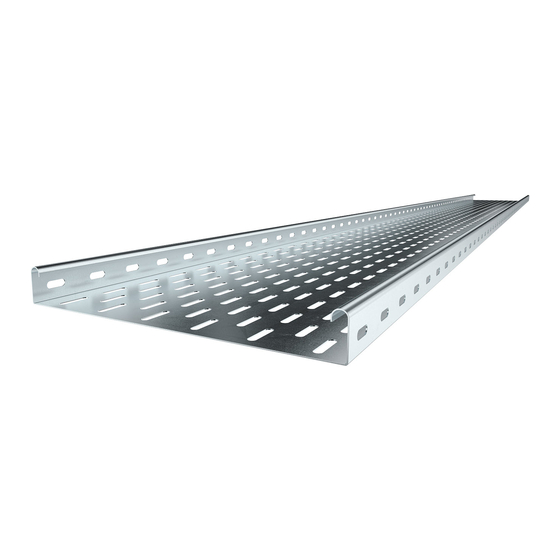
“1.6 Applicable docu- ments” on page 6. 4 1 1 Cable trays Fig 1: Unperforated and perforated tray Unperforated cable tray (MKSU, SKSU) Perforated cable tray (MKS, SKS, DKS, EKS, IKS) 8 | EN OBO Bettermann... -
Page 9: Connectors
System overview Cable tray rail with rounded rail edge Cable tray base Connector perforation 4 1 2 Connectors The following parts can be interconnected using connectors: – Cable tray with cable tray – Cable tray with fitting Fig 2: Connector Designation /type Function Application... -
Page 10: Fittings
RB 90 90° bend, Creation of 90° bend, hori- 400–600 mm radius 150 mm zontal tray width Connector perforation Fastening material retainer 400–600 mm tray width Tab 2: Overview of 90° bends 10 | EN OBO Bettermann... - Page 11 System overview 45° bends Fig 4: 45° bends Designation /type Function Application RB 45 45° bend, Creation of 45° bend, hori- 100–300 mm radius 50 mm zontal tray width Fastening material, FRS Fastening to cable tray 100–600 mm truss-head bolt with combi- tray width nation nut RB 45 45°...
- Page 12 Connector perforation Fastening material retainer 400–600 mm tray width Fastening material, FRS Fastening on cable trays 100–600 mm truss-head bolt with com- tray width bination nut Tab 4: Overview of add-on tees 12 | EN OBO Bettermann...
- Page 13 System overview T branch pieces Fig 6: T branch pieces Designation /type Function Application RT T branch piece incl. Creation of 90° branch 100–300 mm fastening material tray width Fastening material, FRS Fastening to cable tray 100–600 mm truss-head bolt with com- tray width bination nut RT T branch piece with...
- Page 14 RK cross-over with Creation of 90° branch 400–600 mm connector perforation tray width Connector perforation Acceptance of fastening 400–600 mm material tray width Tab 6: Overview of cross-overs 14 | EN OBO Bettermann...
- Page 15 System overview Vertical bend, rising/vertical bend, falling Fig 8: Vertical bend, rising/falling Designation /type Function Application Vertical bend, rising Creation of 90° vertical 100–600 mm radius 180 mm bend, rising vertically tray width Vertical bend, falling Creation of 90° bend, 100–600 mm radius 120 mm falling vertically...
- Page 16 Connection of adjustable 100–600 mm bend element with cable tray width tray Curved slot Variable angle adjustment Securing screw Angle fixing SKS hinge screw Fastening of adjustable M8x16 bend element Tab 8: Overview of adjustable bend elements 16 | EN OBO Bettermann...
-
Page 17: Cover For Cable Trays
System overview 4 1 4 Cover for cable trays Covers for cable trays are available without fastening material or with pre-mounted turn buckles. Fig 10: Covers with fastening material for cable trays Designation /type Function Application Cover with pre-mounted Protection against weath- 100–600 mm turn buckles ering and dirt... -
Page 18: Cover For Fittings
Turn buckle, pre-assem- Cover fastening Perforated and bled unperforated covers DFB cover Protection against wea- ≥ 300 mm tray 45° bend thering and dirt width Tab 10: Overview, 45° covers for fittings 18 | EN OBO Bettermann... -
Page 19: Accessories
System overview 4 1 6 Accessories Fig 12: Accessories Designation /type Function Application Bottom end plate Creation of cable exit All tray types TSG barrier strip Separation of cables of All tray types different voltages or functions Edge protection strip Cover of cut cable tray All tray types edges, protection against... -
Page 20: Mounting
If unperforated cable trays are cut, then the connector perforation must be re-drilled. When mounting the FRS truss-head bolts and SKS hinge screws made of steel or stainless steel from OBO Bettermann, the following tightening torque must be applied: Thread... -
Page 21: Cutting The Cable Tray
Mounting Cutting the cable tray Cut the cable ladders according to the local circumstances. Risk of cutting! CAUTION During cutting work, metal chips or sharp cut edges can cause injuries to eyes and hands! - Wear protective glasses and gloves. - Deburr cut edges. -
Page 22: Mounting The Joint Plate
Fig 14: Applying the edge protection strip 1. Cut the edge protection strip to size. 2. Clamp the edge protection strip to the edge of the cable tray. 22 | EN OBO Bettermann... -
Page 23: Connecting Cable Trays
Mounting Connecting cable trays Cable trays are connected in a straight or angled direction using various connectors. Straight connectors connect cable trays according to their length. Angle connectors can be used to route trays horizontally at angles of different sizes or to create corners. Adjustable connectors create rises or drops. - Page 24 The RLVK straight connector is used with the cable tray heights 35 and 60 mm. The connector is fastened with FRS M6 truss-head bolts and combination nuts. Fig 17: Inserting RLVK straight connectors 1. Insert the straight connectors on the inner side of the rail. 24 | EN OBO Bettermann...
- Page 25 Mounting Fig 18: Screw on the RLVK straight connector 2. Screw on the straight connector. Screw-on cable tray systems 25 | EN...
- Page 26 Fig 19: Inserting RLVL straight connectors 1. Insert the straight connectors on the inner side of the rail. Fig 20: Screwing on the RLVL straight connector 2. Screw on the straight connector. 26 | EN OBO Bettermann...
- Page 27 Mounting RWVL straight and angle connector The RWVL straight and angle connector is used with the cable tray heights 35 and 60 mm. The connector is screwed on with FRS M6 truss- head bolts and combination nuts. Fig 21: Inserting RWVL straight and angle connectors 1.
-
Page 28: Creating An Angled Connection
1. Measure the angle and draw it onto the cable trays accordingly. 2. Cut the cable trays with an angle grinder. Fig 24: Bend the RWVL straight and angle connector 3. Bend the angle connector to the desired angle. 28 | EN OBO Bettermann... - Page 29 Mounting Fig 25: Screwing on the RWVL straight and angle connector 1. Insert the angle connector on the inner sides of the rail. 2. Screw on the angle connector. Screw-on cable tray systems 29 | EN...
- Page 30 2. Notch out the second cable tray rail on both sides by 50 mm. Fig 27: Mounting WKV angle connectors 3. Insert the straps of the angle connector in the inner sides of the rail. 4. Screw on the angle connector. 30 | EN OBO Bettermann...
- Page 31 Mounting 90° internal corner with REV corner connector The REV corner connector is mounted to create 90° internal corners with a large radius, allowing the maintenance of the minimum cable bend radii. The REV corner connector is used with the cable tray heights 35, 60 and 110 mm.
-
Page 32: Creating A Vertical Connection
Securing screw Fig 31: Screwing on the floor end plates 1. Pre-drill unperforated cable trays for the mounting of the floor end plates. 2. Screw the floor end plates to the ends of the cable trays. 32 | EN OBO Bettermann... - Page 33 Mounting Fig 32: Screwing on the RGV adjustable connector to the cable tray 3. Insert the adjustable connector in the inner sides of the rail. 4. Screw on the adjustable connectors. Fig 33: Tightening the hinge screw 5. Adjust the angle on the adjustable connectors and fix with a hinge screw.
- Page 34 Mounting Fig 34: Tighten the securing screw 7. Screw on the adjustable connectors. 8. Screw on the locking screw in the slot or other available drill hole. 34 | EN OBO Bettermann...
-
Page 35: Mounting Fittings
Mounting Mounting fittings Vertical and horizontal changes of direction are created with fittings. Normally, fittings of up to 300 mm width are mounted on cable trays with the WKV angle connectors supplied. Fittings with a width of 400 mm or more have a connector perforation and are mounted on cable trays with FRS M6 truss-head bolts and combination nuts. - Page 36 0 – Fig 36: Example of 90° bend fitting support 1. Support the fitting with a support structure at a distance of 250–300 mm from the edge. 2. Mount an additional support element under the fitting. 36 | EN OBO Bettermann...
-
Page 37: Mounting Wkv Angle Connections On A Fitting
Mounting 5 5 2 Mounting WKV angle connections on a fitting The supplied angle connectors must first be mounted on the fitting with the supplied FRS M6 truss-head bolts and combination nuts. The WKV angle connector is mounted in the same way on all fittings with a width of 100–300 mm. -
Page 38: Mounting The 45°/90° Bend
3. Push the 90° bend onto cable trays. In so doing, the external cable tray rail is located within the fitting and the internal rail outside the fitting. Fig 40: Screwing on a 90° bend 4. Screw the 90° bend to cable trays. 38 | EN OBO Bettermann... - Page 39 Mounting Without connector, 400–600 mm cable tray width Bends with a width of 400 mm or more have connector perforation. Bends with a side height of 35 or 60 mm are mounted with RLVK 35/60 straight connectors and a joint plate. Bends with a side height of 85 or 110 mm are mounted with RLVL 85/110 straight connectors and a joint plate.
-
Page 40: Mounting A Falling/Rising Vertical Bend
2. Screw the vertical bend to the first cable tray. 3. Push the second cable tray into the vertical bend. 4. Screw the vertical bend to the second cable tray. 40 | EN OBO Bettermann... -
Page 41: Mounting An Add-On Tee
Mounting 5 5 5 Mounting an add-on tee Add-on tees are mounted to create T branches with small bend radii. Depending on their width, add-on tees are available with or without WKV angle connectors. With connector, 100–300 mm cable tray width 1. - Page 42 Mounting Fig 47: Screwing the branching cable tray to the add-on tee 6. Push the branching cable tray onto the straps of the angle connector. 7. Screw on the cable tray. 42 | EN OBO Bettermann...
- Page 43 Mounting Without connector, 400–600 mm cable tray width Add-on tees with a width of 400 mm or more have connector perforation. Add-on tees with a side height of 35 or 60 mm are mounted with RLVK 35/60 straight and angle connectors. Add-on tees with a side height of 85 or 110 mm are mounted with RLVL 85/110 straight and angle connec- tors.
- Page 44 8. Push the RLVK or RLVL straight and angle connector of the branching cable tray into the add-on tee. 9. Screw the RLVK or RLVL straight and angle connector to the add-on tee. 10. Screw the joint plate to the add-on tee. 44 | EN OBO Bettermann...
-
Page 45: Mounting The T Branch Piece
Mounting 5 5 6 Mounting the T branch piece T branch pieces are mounted to create T branches with large bend radii. Depending on their width, T branch pieces are available with or without WKV angle connectors. With connector, 100–300 mm cable tray width 1. - Page 46 Mounting Fig 53: Screwing on the T branch piece 3. Screw the cable trays to the T branch piece. 46 | EN OBO Bettermann...
- Page 47 Mounting Without connector, 400–600 mm cable tray width T branch pieces with a width of 400 mm or more have connector perfora- tion. T branch pieces with a side height of 35 or 60 mm are mounted with RLVK 35/60 straight and angle connectors. T branch pieces with a side height of 85 or 110 mm are mounted with RLVL 85/110 straight and angle connectors.
-
Page 48: Mounting A Cross-Over
Fig 56: Cross-over with WKV angle connectors Fig 57: Pushing cable trays onto the cross-over 2. Push the cable trays onto the cross-over. The straps of the WKV angle connector are on the inner side of the cable tray rails. 48 | EN OBO Bettermann... - Page 49 Mounting Fig 58: Screwing on a cross-over 3. Screw the cable trays to the cross-over. Screw-on cable tray systems 49 | EN...
- Page 50 The straight and angle connectors are screwed on with FRS M6 truss-head bolts and combination nuts. Fig 59: Cross-over with RLVL straight and angle connectors and joint plates Fig 60: Mounting a cross-over with RLVL straight and angle connectors 50 | EN OBO Bettermann...
-
Page 51: Mounting Adjustable Bend Elements
Mounting 5 5 8 Mounting adjustable bend elements Adjustable bend elements are used to create height offsets with flexible bends. Adjustable bend elements are mounted on the cable tray with a half adjustable connector and FRS M6 truss-head bolts and combin- ation nuts. - Page 52 4. Fasten adjustable bend elements to adjustable connectors with SKS M8x16 hinge screws. 5. Adjust the angle. 6. Screw on the locking screws in the slot or other available drill hole. 7. Mount other adjustable bend elements with hinge screws and locking screws. 52 | EN OBO Bettermann...
-
Page 53: Mounting A Reducer Profile/End Closure
Mounting 5 5 9 Mounting a reducer profile/end closure Reducer profiles/end closures are used to reduce tray widths or to close them off completely. Reducer profiles/end closures have connector per- foration and are screwed on with FRS M6 truss-head bolts and combina- tion nuts. - Page 54 Mounting Fig 67: Screwing on the joint plate and RWVL straight and angle connector 5. Screw on the joint plate. 54 | EN OBO Bettermann...
- Page 55 Mounting Mounting an end closure 1. With unperforated, cut cable trays, pre-drill mounting perforations. Fig 68: Bending straps 2. Bend the straps on the end closure inwards by 90°. Fig 69: Mounting an end closure 3. Push the end closure into the cable tray. In so doing, the straps touch the inner edge of the rail and the cable tray base.
-
Page 56: Mounting Barrier Strips
1. Drill a hole in the cable tray rail, if it does not yet exist. 2. Screw the earthing terminal on the cable tray rail with an FRSB 6x12 screw. 3. Electrically connect the earthing terminal to the overall equipotential bonding. 56 | EN OBO Bettermann... -
Page 57: Mounting The Cover
Mounting Mounting the cover Covers can be mounted as follows: – With cover clamps – With turn buckles mounted at a later date – With pre-mounted turn buckles 5 8 1 Mounting the cover with cover clamp Fig 72: Clamping the cover clamp to the cover 1. - Page 58 Mounting Fig 74: Snap on the cover. 3. Snap the cover onto cable tray rails using cover clamps. 58 | EN OBO Bettermann...
-
Page 59: Mounting The Cover With Turn Buckle
Mounting 5 8 2 Mounting the cover with turn buckle Turn buckles are either pre-mounted at the factory or can be mounted at a later date in the case of unperforated covers. Depending on the type, the turn buckle is screwed or riveted to the cover. In both cases, the holes must be pre-drilled in the cover. -
Page 60: Mounting A Fitting Cover
Mounting a fitting cover The fittings are supplied with pre-mounted turn buckles. The mounting is the same as the mounting of the cable tray cover, see “5.8.2 Mounting the cover with turn buckle” on page 59. 60 | EN OBO Bettermann... - Page 61 Maintaining the system Maintaining the system The stability and function of the screw-on cable tray systems can be im- paired by external influences, such as damage or machine vibrations. Loose connection elements must be retightened and damaged parts replaced. The connection to the overall equipotential bonding must be continually intact and thus checked regularly.
- Page 62 A4 = Stainless steel Cable trays, length 3,000 mm Designation Type Side height Width mm Surface Item no MKS cable tray MKS 310 FS 6053548 MKS cable tray MKS 315 FS 6053572 MKS cable tray MKS 320 FS 6053599 MKS cable tray...
- Page 63 Technical data Designation Type Side height Width mm Surface Item no MKS cable tray MKS 860 FS 6057535 MKS cable tray MKS 110 FS 6060102 MKS cable tray MKS 120 FS 6060196 MKS cable tray MKS 130 FS 6060307 MKS cable tray MKS 140 FS 6060404 MKS cable tray...
- Page 64 SKSU cable tray SKSU 110 FS 6063403 SKSU cable tray SKSU 120 FS 6063438 SKSU cable tray SKSU 130 FS 6063454 SKSU cable tray SKSU 140 FS 6063470 SKSU cable tray SKSU 150 FS 6063497 64 | EN OBO Bettermann...
- Page 65 Technical data Designation Type Side height Width mm Surface Item no SKSU cable tray SKSU 155 FS 6063500 SKSU cable tray SKSU 110 FT 6064795 SKSU cable tray SKSU 120 FT 6064833 SKSU cable tray SKSU 130 FT 6064884 SKSU cable tray SKSU 140 FT 6064922 SKSU cable tray...
- Page 66 Corner connector 60 REV 60 FS 6067972 Corner connector 60 REV 60 DD 6069410 Corner connector 60 REV 60 A2 6068022 Corner connector 60 REV 60 A4 6068054 Corner connector 85 REV 85 FS 6067980 66 | EN OBO Bettermann...
- Page 67 Technical data Designation Type Side height mm Surface Item no Corner connector 85 REV 85 DD 6069320 Corner connector 110 REV 110 FS 6067999 Corner connector 110 REV 110 DD 6069339 Corner connector 110 REV 110 A2 6068049 Fittings Designation Type Side Width mm...
- Page 68 RB 90 630 FS 6043232 90° bend 60 RB 90 610 FT 7125100 90° bend 60 RB 90 615 FT 7125189 90° bend 60 RB 90 620 FT 7125220 90° bend 60 RB 90 630 FT 7125305 68 | EN OBO Bettermann...
- Page 69 Technical data Designation Type Side Width mm Surface Item no height mm 90° bend 60 RB 90 610 A2 7134122 90° bend 60 RB 90 620 A2 7134130 90° bend 60 RB 90 630 A2 7134138 90° bend 60 RB 90 610 A4 7134286 90°...
- Page 70 Add-on tee 60 RAA 650 A4 7136252 Add-on tee 60 RAA 660 A4 7136271 Add-on tee 85 RAA 810 FS 7002475 Add-on tee 85 RAA 820 FS 7002491 Add-on tee 85 RAA 830 FS 7002513 70 | EN OBO Bettermann...
- Page 71 Technical data Designation Type Side Width mm Surface Item no height mm Add-on tee 85 RAA 810 FT 7122109 Add-on tee 85 RAA 820 FT 7122213 Add-on tee 85 RAA 830 FT 7122310 Add-on tee 85 RAA 840 FS 7002521 Add-on tee 85 RAA 850 FS 7002556...
- Page 72 RBV 615 S FS 7007009 90° vertical bend, rising, 60 RBV 620 S FS 7007013 90° vertical bend, rising, 60 RBV 630 S FS 7007017 90° vertical bend, rising, 60 RBV 640 S FS 7007021 72 | EN OBO Bettermann...
- Page 73 Technical data Designation Type Side Width mm Surface Item no height mm 90° vertical bend, rising, 60 RBV 650 S FS 7007025 90° vertical bend, rising, 60 RBV 660 S FS 7007029 90° vertical bend, rising, 60 RBV 610 S FT 7007006 90°...
- Page 74 RBV 150 F FS 7007366 90° vertical bend, falling, 110 RBV 160 F FS 7007373 90° vertical bend, falling, 110 RBV 110 F FT 7007468 90° vertical bend, falling, 110 RBV 115 F FT 7007353 74 | EN OBO Bettermann...
- Page 75 Technical data Designation Type Side Width mm Surface Item no height mm 90° vertical bend, falling, 110 RBV 120 F FT 7007470 90° vertical bend, falling, 110 RBV 130 F FT 7007359 90° vertical bend, falling, 110 RBV 140 F FT 7007474 90°...
- Page 76 DRL 400 FT 6051413 Cover with turn buckle DRL 500 FT 6051448 Cover with turn buckle DRL 600 FT 6051472 Cover with turn buckle DRL 100 DD 6052703 Cover with turn buckle DRL 150 DD 6052706 76 | EN OBO Bettermann...
- Page 77 Technical data Cover with turn buckle DRL 200 DD 6052709 Cover with turn buckle DRL 300 DD 6052712 Cover with turn buckle DRL 400 DD 6052715 Cover with turn buckle DRL 500 DD 6052718 Cover with turn buckle DRL 550 DD 6052721 Cover with turn buckle DRL 600 DD...
- Page 78 Cover for 45° bend DFB 45 600 FS 7128924 Cover for 45° bend DFB 45 400 DD 7131879 Cover for 45° bend DFB 45 500 DD 7131887 Cover for 45° bend DFB 45 550 DD 7131895 78 | EN OBO Bettermann...
- Page 79 Technical data Designation Type Width mm Surface Item no Cover for 45° bend DFB 45 600 DD 7131909 Cover for 45° bend DFB 45 100 A2 7133901 Cover for 45° bend DFB 45 200 A2 7133928 Cover for 45° bend DFB 45 300 A2 7133936 Cover for 45°...
- Page 80 Cover for T branch piece DFT 600 FS 7128320 Cover for T branch piece DFT 400 DD 7129386 Cover for T branch piece DFT 500 DD 7129408 Cover for T branch piece DFT 600 DD 7129424 80 | EN OBO Bettermann...
- Page 81 Technical data Designation Type Width mm Surface Item no Cover, cross-over, with turn buckles, for DFK 100 FS 7128614 RK 100 Cover, cross-over, with turn buckles, for DFK 150 FS 7128622 RK 150 Cover, cross-over, with turn buckles, for DFK 200 FS 7128630 RK 200 Cover, cross-over, with turn buckles, for...
- Page 82 7131680 height 85 Cover for 90° vertical bend, falling, side DBV 85 400 F DD 400 7131684 height 85 Cover for 90° vertical bend, falling, side DBV 85 500 F DD 500 7131688 height 85 82 | EN OBO Bettermann...
- Page 83 Technical data Designation Type Width mm Surface Item no Cover for 90° vertical bend, falling, side DBV 85 600 F DD 600 7131692 height 85 Cover for 90° vertical bend, falling, side DBV 110 100 F 7131030 height 110 Cover for 90° vertical bend, falling, side DBV 110 150 F 7131032 height 110...
- Page 84 Barrier strip TSG 85 DD 3,000 6062331 Barrier strip TSG 85 A2 3,000 6062173 Barrier strip TSG 110 FS 3,000 6062122 Barrier strip TSG 110 DD 3,000 6062335 Barrier strip TSG 110 A2 3,000 6062255 84 | EN OBO Bettermann...
- Page 85 Technical data Joint plates Designation Type Width Surface Item no Joint plate SSLB 100 FS 7070205 Joint plate SSLB 150 FS 7070209 Joint plate SSLB 200 FS 7070213 Joint plate SSLB 300 FS 7070217 Joint plate SSLB 400 FS 7070221 Joint plate SSLB 500 FS 7070225...
- Page 86 RWEB 110 DD 110 7107455 Reducer profile/end closure RWEB 120 DD 110 7107471 Reducer profile/end closure RWEB 130 DD 110 7107501 Reducer profile/end closure RWEB 140 DD 110 7107536 Reducer profile/end closure RWEB 150 DD 110 7107552 86 | EN OBO Bettermann...
- Page 87 Technical data Designation Type Side height Width Surface Item no Reducer profile/end closure RWEB 160 DD 110 7107562 Reducer profile/end closure RWEB 155 DD 110 7107560 Miscellaneous Designation Type For plate Dimension h Surface Item no thickness Edge protection strip KSB 2 PVC 0.75–2 6072909...
- Page 88 OBO Bettermann Holding GmbH & Co. KG P.O. Box 1120 58694 Menden GERMANY Customer Service Germany Tel.: +49 (0)2373 89-1700 Fax: +49 (0)2373 89-1238 E-mail: export@obo.de www.obo.global...
Need help?
Do you have a question about the MKS 310 FS and is the answer not in the manual?
Questions and answers