
Related Manuals for OBO Bettermann GR-Magic


Summary of Contents for OBO Bettermann GR-Magic
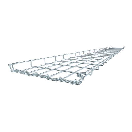
- Page 1 Magic mesh cable tray system ® Brief system instructions for GR-Magic ® Building Connections 06/2017 EN...
-
Page 2: Table Of Contents
Cables can be damaged on bending. When inserting the cables, ensure that the minimum bending radius, prescribed by the cable manufacturer, is observed. © 2013 OBO BETTERMANN GmbH & Co. KG Reprinting, even of extracts, as well as photographic or electronic reproduction are prohibited. -
Page 3: Straight Connection Of Mesh Cable Trays
Straight connection of mesh cable trays The GR-Magic mesh cable tray system with shaped connector for screwless quick mounting ® guarantees the shortest possible installation times, even for complex mounting operations. Connection of lengths stock lengths Fig 2 1 1 Connect the mesh cable trays, as shown. -
Page 4: Connection Of Cut Mesh Cable Trays
Fig 2 2 3 Use of the quick connector type GRS 3.9 or GRS 4.8 ana- logue to the mesh cable tray wire thickness. For use with mesh cable trays up to a width of 150 mm. 4 | DE OBO Bettermann... - Page 5 Connection of cut mesh cable trays Fig 2 2 4 Use of the quick connector type GRV 245. DE | 5 Brief system instructions, Magic mesh cable tray systems ®...
-
Page 6: Use Of Fittings
1x GEV 36 Mesh cable tray bends created on-site with small radius Below, you will find the cutting templates/samples of the mesh cable bends to be created with a small radius. 1x GSV 34 1x GSV 34 6 | DE OBO Bettermann... - Page 7 Mesh cable tray bends created on-site with small radius 1x GSV 34 1x GSV 34 2x GSV 34 DE | 7 Brief system instructions, Magic mesh cable tray systems ®...
- Page 8 Mesh cable tray bends created on-site with small radius 2x GSV 34 2x GSV 34 8 | DE OBO Bettermann...
-
Page 9: Mesh Cable Tray Bends Created On-Site With Large Radius
Mesh cable tray bends created on-site with large radius Below, you will find the cutting templates/samples of the mesh cable bends to be created with a large radius. 1x GEV 36 1x GSV 34 3x GEV 36 4x GEV 36 5x GEV 36 DE | 9 Brief system instructions, Magic... - Page 10 Mesh cable tray bends created on-site with large radius 1,195 7x GEV 36 1,577 1,035 9x GEV 36 1,832 1,190 11x GEV 36 10 | DE OBO Bettermann...
- Page 11 Reduction created on-site, asymmetrical A reduction of the mesh cable tray width by 100 mm can be created. GSV 34 joint connector Please refer to Fig. 2.2.2 for the required number minus one connector being replaced by the GEV 36. GSV 34 joint connector GEV 36 corner connector Fig 3 4 1...
- Page 12 When using the GEV 36 corner connector, the same number of GSV 34 joint connectors can be left out. GSV 34 joint connector GEV 36 corner con- nector Fig 3 4 3 Fig 3 4 4 Fig 3 4 5 12 | DE OBO Bettermann...
- Page 13 Earthing connection Integration of the mesh cable trays into the equipotential bonding. Please refer to the installation regulations valid for you for the number of connections. Joint connector, GSV 34 Earthing screw, EKL Fig 3 5 1 Integration of a cut mesh cable tray Connection and earthing terminal, VEK-GRM Earthing screw, EKL...
- Page 14 Negative height offset created on-site Positive height offset created on-site 14 | DE OBO Bettermann...
- Page 15 Falling mesh cable tray bends created on-site Rising mesh cable tray bends created on-site DE | 15 Brief system instructions, Magic mesh cable tray systems ®...
- Page 16 4 for the number of type GSV 34 mesh cable tray connectors in the base. If the GEV 36 corner connector is used, the same num- ber of GSV 36 joint connectors can GSV 34 be left out. 16 | DE OBO Bettermann...
- Page 17 Vertical branch created on-site Fig 4 1 1 Side view of the vertical branch after completion. Fig 4 1 2 Notching out of the wires in the base of the horizontally routed mesh cable tray. Fig 4 1 3 Notching out of the side grids of the vertically routed mesh cable tray.
- Page 18 OBO Bettermann GmbH & Co. KG P.O. Box 1120 58694 Menden GERMANY Customer Service Germany Tel. +49 (0)2373 89-1700 Fax +49 (0)2373 89-1238 export@obo.de Building Connections...
Need help?
Do you have a question about the GR-Magic and is the answer not in the manual?
Questions and answers