
Related Manuals for Zodiac Z550iQ


Summary of Contents for Zodiac Z550iQ
- Page 1 Z550iQ Instructions for installation and use - English Heat pump Translation of the original instructions in French More documents on: www.zodiac.com H0673700_REVA - 2020/10...
- Page 2 WARNINGS Carefully read the instructions in this manual before using the unit. • Before handling the appliance, it is vital that you read this installation and user manual, as well as the "Warranties" booklet delivered with the appliance. Failure to do so may result in material damage or serious or fatal injury and will void the warranty.
- Page 3 vicinity of the moving parts when the appliance is in operation. Moving parts can cause serious injury or even death. WARNINGS ASSOCIATED WITH ELECTRICAL APPLIANCES • The power supply to the appliance must be protected by a dedicated 30 mA Residual Current Device (RCD), complying with the standards and regulations in force in the country in which it is installed.
- Page 4 • During the appliance's annual sealing test in accordance with applicable legislation, the high and low pressure switches must be checked to ensure that they are securely fastened to the cooling circuit and that they cut off the electrical circuit when tripped.
-
Page 5: Table Of Contents
CONTENTS ❶ Installation 1.1 I Selecting the location 1.2 I Hydraulic connections 1.3 I Electricity supply connections 1.4 I Option connections ❷ Use 2.1 I Operating principle 2.2 I User interface presentation 2.3 I Operation 2.4 I User functions 2.5 I Connecting to the iAquaLink™ app ❸... -
Page 6: ❶ Installation
❶ Installation 1.1 I Selecting the location • When the appliance is installed and protected by a residual current device (RCD) with a maximum amperage of 30 mA, it should be installed at a distance of at least 2 metres from the edge of the pool. -
Page 7: I Hydraulic Connections
1.2 I Hydraulic connections • The device will be connected with a Ø50 PVC pipe, using the half union connectors supplied (see § “5.1 I Description”), to the pool's filtration circuit, after the filter and before the water treatment. • Respect the direction of hydraulic connection. •... -
Page 8: I Electricity Supply Connections
1.3 I Electricity supply connections • Before any work inside the appliance, you must cut the electricity supply as there is a risk of electric shock which may cause material damage, serious injury or even death. • Only a qualified and experienced technician is authorised to carry out cabling work within the appliance or to replace the power cord. -
Page 9: I Option Connections
1.3.1 Wiring on a spring-cage terminal block ❶ • Pull the lever up as far as it will go, then connect the cable (see figure ❷ • Return the lever back to its initial position (see image ❶ ❷ 1.4 I Option connections Connecting the "Heating priority"... - Page 10 1.4.2 "Remote "On/Off" control" option • This option allows the "remote On/Off" function to be enabled by way of a switch installed remotely. • To connect, couple the remote "On/Off" switch (not provided) to terminals 3 - 4 (dry contact). : heat pump terminal board : remote "on/off"...
-
Page 11: ❷ Use
❷ Use 2.1 I Operating principle The heat pump uses the calories (heat) in the air to heat up your pool's water. The process to heat your pool's water to the temperature you want may take a few days as it depends on the weather conditions, the heat pump's power and the difference between the water temperature and the temperature you want. - Page 12 2.2.2 LED strip The LED strip on the front of the appliance gives you a rapid overview of the heat pump's operating status. The following table explains the meaning of the different strip lights. LED 5 HIGH LED 4 LED 3 LED 2 LED 1 Colour...
-
Page 13: I Operation
2.3 I Operation • Check that there are no tools or other foreign objects in the machine. • The panel that provides access to the technical section must be put in place. • Set the valves as follows: valve B wide open, valves A, C, D and E closed : Water inlet valve : By-pass valve : Water outlet valve... -
Page 14: I User Functions
2.4 I User functions 2.4.1 "Automatic keypad lock" function The "automatic keypad lock" function allows the keypad to be disabled when inactive for at least 30 seconds (default value) to prevent mishandling. Locking/unlocking the keypad: • Press simultaneously for 3 seconds. The indicator appears (= locked) or disappears (= unlocked) depending on the keypad's state. - Page 15 2.4.3 Activating/deactivating the "Cooling" mode Information: "Cooling" function • Activating the "Cooling" mode allows the machine's cycle to be automatically reversed to cool the pool water. • When the "Cooling" function is activated, as soon as the water temperature exceeds the setpoint temperature by more than 2°C (see following diagram), the heat pump automatically activates the "Cooling"...
- Page 16 2.4.4 Using and selecting the different active operating modes In "Heating" mode, the heat pump has 3 active operating modes for adjusting its operating speed to the power that is required and the mode that is selected. Depending on the selected operating mode ("BOOST", "SMART" or "ECOSILENCE"), the power delivered by the heat pump can vary over a predefined range (depending on the speed of its compressor and fan).
-
Page 17: I Connecting To The Iaqualink™ App
Mobile device Home Wi-Fi network Heat pump The Z550iQ heat pump can be remotely controlled from a smartphone or tablet, via the iAquaLink™ app available for iOS and Android systems. Before connecting to the iAquaLink™ app, ensure that you: • Use a Wi-Fi-enabled smartphone or tablet. -
Page 18: ❸ Maintenance
❸ Maintenance 3.1 I Winterising • Winterising is vital to prevent the condenser breaking due to freezing. This is not covered by the warranty. • To avoid damaging the appliance with condensation, do not fully cover it; a winterising cover is provided. -
Page 19: ❹ Troubleshooting
❹ Troubleshooting • Before you contact the retailer, carry out these few simple checks using the following tables if a problem occurs. • If the problem is not resolved, contact your retailer. • : Actions to be performed by a qualified technician only 4.1 I Appliance behaviour •... -
Page 20: I Error Code Display
4.2 I Error code display Display Possible causes Solutions Resetting Pressure fault in the low • LED "steady red" pressure circuit (if problem Call a qualified technician = automatic persists after resetting) Low pressure fault on • LED "flashing red" cooling circuit = press Exchanger clogged with dirt Clean the water exchanger... -
Page 21: I Lighting Of Leds On The Printed Circuit Board
Display Possible causes Solutions Resetting Check the fan motor • LED "steady red" connector. If the problem Fan motor disconnected = automatic E16 / E17 persists, call a qualified • LED "flashing red" Error on the fan motor technician = press Fan motor damaged Replace the fan motor Check the electrical... -
Page 22: I Wiring Diagrams
4.4 I Wiring diagrams 4.4.1 Z550iQ MD4 - MD5 - MD8... - Page 23 4.4.2 Z550iQ TD5 - TD8...
- Page 24 Symbol Description Electronic regulation board Display board (HMI) Fan board Compressor electronic board Splitter board LED board Filter board Fan filter board Black Blue Brown Fan condenser Second speed condenser Compressor condenser Compressor EXP VALVE Electronic expansion valve F1 - F2 Fuse Fan motor FAN HEATER Conveyor resistor...
-
Page 25: ❺ Characteristics
❺ Characteristics 5.1 I Description Z550iQ Ø50 connector to be glued (x2) Condensate drainage kit (Ø18) Winterising cap (x2) Winterising cover Heating priority Technical room kit Condensation tray PAC NET (cleaning product) : Included : Available as an accessory... -
Page 26: I Technical Data
5.2 I Technical data Z550iQ Performances: air at 28°C / water at 28°C / humidity at 80 % Power output (max-min speed) 12.5 - 7.9 15 - 7.6 15.5 - 7.1 20 - 10.8 20 - 11.2 Power consumed (max-min speed) 2 - 1.05... -
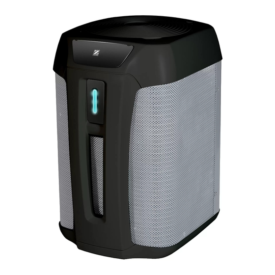
Page 27: I Dimensions And Marking
5.3 I Dimensions and marking Bottom Front Rear Grid LED strip User interface Technical access door Pool water inlet Pool water outlet Evaporator Condensates drain... - Page 28 Pour plus d’informations, enregistrement produit et support client : For more information, product registration and customer support: www.zodiac.com ©2020 Zodiac Pool Systems LLC. All rights reserved. ZODIAC® is a registered trademark of Zodiac International, S.A.S.U., used under license. All other trademarks are the property of their respective owners.
Need help?
Do you have a question about the Z550iQ and is the answer not in the manual?
Questions and answers