Zodiac Z300 Series Instructions For Installation And Use Manual
Hide thumbs
Also See for Z300 Series:
- Instructions for installation and use manual (22 pages) ,
- Instructions for installation and use manual (96 pages) ,
- Instruction manual (3 pages)

Related Manuals for Zodiac Z300 Series


Summary of Contents for Zodiac Z300 Series
- Page 1 Instructions for installation and use English More documents on: www.zodiac-poolcare.com H0439100.B - 2014/09...
- Page 2 • Read this notice carefully before installing, maintaining or repairing this appliance! • The symbol indicates important information that you must take into account to avoid the risk of damage to persons or the appliance. • The symbol indicates useful information as an indication. Warning •...
-
Page 3: Table Of Contents
Contents 1. Information before installing ........................3 1.1 General delivery terms and conditions ...................... 3 1.2 Content ................................3 1.3 Technical specifications ..........................3 2. Installation ............................... 3 2.1 Selecting an installation site ........................3 2.2 Installing the appliance ..........................4 2.3 Hydraulic connections .......................... -
Page 4: Information Before Installing
1. Information before installing 1.1 General delivery terms and conditions All equipment, even postage and packing paid, travels at the risks and perils of the recipient. The latter must make written reserves on the transporter’s delivery documents if damage during transport is discovered (confirmed by registered letter to the transporter within 48 hours). -
Page 5: Installing The Appliance
2.2 Installing the appliance • Install on a stable, solid surface (concrete slab for example) which is level, • Protect from risks of flooding due to condensates from the appliance when it is running (see §2.3). Fixing holes The anti-vibration blocs are fitted under the base of the heat pump. The heat pump can be fixed to the ground using the brackets at the base of the unit (attachments not included). - Page 6 • Electrical conduits must be secured, • Tolerance for voltage variation: ± 6% (during operation), • Use cable suitable for outdoor use, type RO2V or equivalent in countries outside of the European community, with an outer diameter between 9 and 18 mm, •...
-
Page 7: Use
• Remote on/off control - Function: connect a remote «on/off» button - Thanks to a zero-potential free contact, without 230 V - 50 Hz polarity, connect the cable to the busbar between terminals 7-8, - Activate the command by pressing for 5 seconds when regulation is not on standby: then , then press 3 seconds on... -
Page 8: Starting Up The Appliance
3.1.1 Reading and changing parameters 3.1.2 Locking and releasing the key pad Press for 3 seconds: 3.2 Starting up the appliance • Check that no tools or other objects have been left inside the device. • The access door for technical components must be fitted. •... -
Page 9: Checks To Perform After Start-Up
• Set the required water temperature: - press to increase temperature, - press to decrease temperature, When the pool reaches the required temperature, the heat pump will automatically stop. • Set the water flow-rate using the menu , when the indicator is steady: press to display the water flow-rate status:... -
Page 10: Additional Recommendations
4.2 Additional recommendations Relative to pressurised appliances (PED-97/23/EC) 4.2.1 Installation and maintenance • It is prohibited to install the appliance close to combustible materials or close to the air intake on an adjacent building. • For some appliances it is imperative to use the protection grate accessory if the installation is located in an unregulated access area. - Page 11 Display Designation Cause Solution Reset Phase order • Wiring incorrect on the • Reverse the phases on Switch the power defect (only on supply terminal board the supply terminal board supply off or press three-phased of the device, (without power to the models) •...
-
Page 12: Appliance Malfunctions
5.2 Appliance malfunctions Malfunction Possible causes Solutions The device is not • No display • Check the supply voltage and the fuse F1 operational • The pool temperature is above the set- • Increase the set-point temperature point temperature • Check the meaning of message §5.1 •... -
Page 13: Registering The Product
• Note: your device can produce several litres of water per day. 6. Registering the product Register your product on our website: be the first to be informed of new Zodiac® products and special offers, help us to constantly improve our product quality. Europe & Rest of the World www.zodiac-poolcare.com... - Page 14 Electric diagram Z300 M4-M5-M7 H0439100.B - EN - 2014-09...
- Page 15 Z300 T5 H0439100.B - EN - 2014-09...
- Page 16 Z300 MD5 H0439100.B - EN - 2014-09...
- Page 17 Z300 MD8 H0439100.B - EN - 2014-09...
- Page 18 Z300 TD5-TD8 H0439100.B - EN - 2014-09...
- Page 19 L-N-PE Power supply (230V/1N/50 Hz) L1-L2-L3-N-PE Power supply (400V/3N/50 Hz) Earth Pump control (max. 8A contact) Electrical heating control (max. 2A contact) Alarm control(max. 2A contact) Remote control 4-way valve coil Electronic board for regulation Electronic board for display Fan capacitor Compressor capacitor Filter Progressive starter...
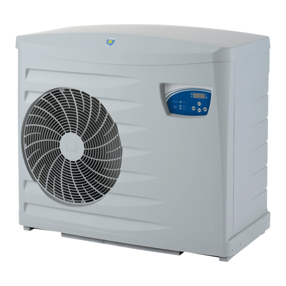
- Page 20 Dimensions et description Base Front pannel cowl Technical door Back pannel Post Grid Regulator Ø1” ½ water pool inlet Ø1” ½ water pool outlet Evaporator Stuffing box Z300 Weight (Kg) M5 - T5 - MD5 - TD5 MD8 - TD8 H0439100.B - EN - 2014-09...
- Page 22 Votre revendeur / your retailer Pour plus de renseignements, merci de contacter votre revendeur. For further information, please contact your retailer. ZODIAC® is a registered trademark of Zodiac International, S.A.S.U., used under license.
Need help?
Do you have a question about the Z300 Series and is the answer not in the manual?
Questions and answers