
Related Manuals for Elite Models Acrocub


Summary of Contents for Elite Models Acrocub
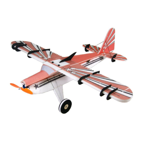
- Page 1 43in EPP Acrocub Instruction Manual Specifications Wingspan: 43.3 in (1100mm) Length: 41.3 in (1050mm) Flying Weight: Approx. 1.5lb (670g)
- Page 2 Dear Customer, Congratulations on your purchase of 43in EPP Acrocub Kit from Value Hobby. We thank you for your generous support, and hope you enjoy your new airplane. At Value Hobby, we hope to offer competitive prices, good performance, and products that you can setup and use with ease.
- Page 3 Before Starting Assembly Unpack your airplane and examine the components. Check for damage of any kind. If you see any damage, please contact Value Hobby immediately. Airframe Parts...
-
Page 4: Recommended Equipment
RECOMMENDED EQUIPMENT Product Quantity FrSky Taranis Q X7 Transmitter and Receiver Set FRY-RC-5938 Towerpro MG90s TWP-SV-0358 GForce E400 2212-1250KV Brushless Motor VHB-MT-5336 GForce 30A Brushless ESC HWG-SC-0238 GForce Elite Series 1600mAh 3S LiPO FLM-LP-5577 Gemfan 10*4.5 Prop GFH-MP-2665 Foam Safe Glue VHB-AC-2511 Hot Melt Glue VHB-AC-2988... -
Page 5: Section 1 Wing Assembly
Section 1 Wing Assembly 1 x Left wing First, apply foam glue to join the parts of the wing. 1 x Right wing 1 x Central wing 2 x Leading edge flap (White EPP foam) 6 x Side force generators (SFG) 1 x Heat shrink tubing (150mm) 2 x Aileron control horn (White PVC plastic) 2 x Aileron arm... - Page 6 Apply foam glue to the pre-cut slot on the leading Leading edge flap Installation edge of the upper and lower surface of the wing. Locate 2 white flap foams, 2 white PVC control horns, Wait for 4-5 minute. Then slide the carbon fiber rod 2 white PVC fixed arms.
- Page 7 Glue the end with control horn to the left side of right Apply foam glue to four pre-cut slots on the leading leading edge flap and to the right side of left leading edge of the wing. Wait for 4-5 minute. Slide two edge flap.
- Page 8 Slide the servo into the servo mounting plate. Then put the servo into the slot and secure the servo. You will need four 9g servos. They are not included. Must be purchased separately. Use the blade to cut the slot of servo extension. The Repeat the same steps for the other 3 servos.
- Page 9 Tighten servo arm to aileron arm using four 2*6mm Slide aileron carbon fiber pushrod and Z-bend screws. into the heat-shrink tubing. Heat the heat- shrink tubing to tighten aileron carbon fiber pushrod and Z-bend together. Fix the aileron arm to the aileron servo. The ruler should perpendicular to the top of servo Slide completed pushrod into the hole of control horn arm.
- Page 10 Glue the six SFG to the wing. There are pre-printed lines at the 1/4 of the leading edge. Apply foam glue to there. Locate the aileron SFG, shown below. Locate the central SFG as shown below. Apply foam glue to the inside of the side force generator (SFG).
-
Page 11: Section 2 Fuselage Assembly
Section 2 Fuselage Assembly Apply foam glue to the pre-cut slot of the fuselage. Slide landing gear reinforced rod into the slot. Locate the left and right fuselage, four landing gear reinforced rods (1*10*206mm x 2, 1*10*305mm x 2), two landing gear cover and one motor mount. Apply foam glue to the pre-cut slot at the bottom of the fuselage. - Page 12 Locate the motor mount. Apply foam glue to the inter-locking joining areas of the left fuselage upper part. Apply glue to the pre-cut slot of the right fuselage. After that, slide the right fuselage into the slot of the left fuselage upper part. Wait for at least 3-5 minute until the glue has cured.
- Page 13 Wing-Fuselage Support Frame Assembly Find the following parts for the wing-fuselage support frame. Assemble the center support bridge first using the three wood pieces as shown below. Be careful when applying not to leave glue on the metal nuts. Glue the center support bridge as well as leading and trailing support piece to the left and right side of the frame.
- Page 14 Draw line along the edge of the support frame with a pen to mark where to apply the glue. Then apply the glue to the marked area. You can also apply glue to the support frame. Test fit the assembled wing-fuselage support frame with the fuselage.
- Page 15 Battery plate installation Locate the wood parts for the battery plate as below. Use the blade to cut a hole on the fuselage. This hole will be used for threading the battery wire through the fuselage. Apply glue to the pre-cut slot at the bottom of the fuselage.
- Page 16 Assembly of fuselage front cover and canopy Apply glue on the fuselage where the front cover meets the canopy. The triangle foam support piece needs to be positioned so it can secure both the front cover piece and the canopy piece. Apply glue to the top of the fuselage head.
- Page 17 Secure the radial motor mount to the wood motor mount. Connect the power to check whether the rotation direction of the motor is correct. If it is reverse rotation, two power cables of the motor and the ESC should be swapped. Connect the motor to the ESC.
- Page 18 Apply glue to the foam cover. Apply the glue to the foam canopy. Secure the fuselage foam cover. Secure the canopy to the fuselage. Now we secure the foam canopy to the fuselage. Apply glue to the left and right edge of the fuselage.
- Page 19 Tail installation Locate a horizontal tail, a vertical tail, two elevator SFG, two foam triangular rods, two elevator carbon fiber rods (1*6*200mm x 1, 1*6*230mm x 1). Apply the glue to the pre-cut slot of the elevator control horn. Apply the glue to the elevator carbon fiber rods. Slide the control horn into the slot.
- Page 20 The control horn should be on the left side of the Secure the 2 3/4in long foam triangle stock to the rudder, as shown below. base of the horizontal tail on the fuselage using the glue. Secure the 10in long foam triangle stock to the bottom of the fuselage using the glue.
- Page 21 Apply glue to the pre-cut slot of the horizontal tail Join the horizontal and vertical tail onto the fuselage. front and back sides. Then secure them with glue. Apply glue to the inter-locking joining area of the vertical tail. Secure the fuselage cover plate onto the fuselage Apply glue to the foam triangular stock.
- Page 22 Slide carbon fiber rod and Z-bend into the heat- shrink tubing. Heat the heat-shrink tubing to tighten carbon fiber rod and Z-bend together. Then secure them with glue. Locate two carbon fiber rods (one 2mm*185mm and one 2mm*285mm), two servo mounting bracket, four Z-bend, four heat-shrink tubing, two long fiberglass servo arms and mounting screws.
- Page 23 Tighten the long fiberglass servo arms to the servo Locate another z-bend. Connect this Z-bend to the arms that came with your servo. rudder control horn. Then join this Z-bend and the 285mm pushrod using heat-shrink tubing. Secure the completed arm to the servo. The rudder and the vertical tail should be aligned.
- Page 24 Connect the elevator servo to the 185mm pushrod, Align the hole of the wood wheel core to the hole of and then to the elevator control horn. The process is the white EPP foam wheel. Then secure them the same as on the rudder. The elevator and the together using glue.
- Page 25 Glue them together. Install the wheel support pieces between the landing gear carbon fiber rods. Use glue to secure them. Locate the 60mm carbon fiber rods. Locate the wheel axle holders. Insert the carbon fiber rod into the landing gear support piece.
- Page 26 After the rod has been securely fastened to the wood Locate the wheel block. support, use some CA to secure the string. Install the wheel block. Secure it with the glue. Secure the wheel axel holder at the end of the landing gear support piece.
- Page 27 Apply the hot melt glue to secure the wheel Glue the other end of the support rod on the vertical tail. Repeat the same steps for both wheels. The CG should be 83mm (3.26in) from leading edge of Locate the two vertical tail support rods the wing.
Need help?
Do you have a question about the Acrocub and is the answer not in the manual?
Questions and answers