Table of Contents
Advertisement
Quick Links
Advertisement
Table of Contents

Related Manuals for INOXPA DIN-FOOD


Summary of Contents for INOXPA DIN-FOOD
- Page 1 INSTALLATION, SERVICE AND MAINTENANCE INSTRUCTIONS DIN-FOOD INOXPA, S.A. c/Telers, 54 Aptdo. 174 E-17820 Banyoles Girona (Spain) Tel. : (34) 972 - 57 52 00 Fax. : (34) 972 - 57 55 02 Email: inoxpa@inoxpa.com www.inoxpa.com Original Manual 01.110.30.00EN 2021/11...
-
Page 4: Safety
FOOD pump. The information published in the instruction manual is based on updated information. INOXPA reserves the right to modify this instruction manual without prior notice. 1.2. START-UP INSTRUCTIONS This Instructions Manual contains essential and useful information for properly operating and maintaining your pump. - Page 5 • Will place the environment in danger due to the release of substances. 1.4.5. Guarantee Any warranty provided shall immediately be cancelled and void ipso jure, and INOXPA shall be compensated for any product liability claim from third parties, if: •...
-
Page 6: Table Of Contents
8.12. DIN-FOOD (close-coupled) parts list ................35 8.13. DIN-FOOD Flushed mechanical seal (bare shaft) ............36 8.14. DIN-FOOD flushed mechanical seal (close-coupled, size 160 and 180 motors) ....37 8.15. DIN-FOOD flushed mechanical seal (close-coupled, size 200 motors) ......38 8.16. -
Page 7: Información General
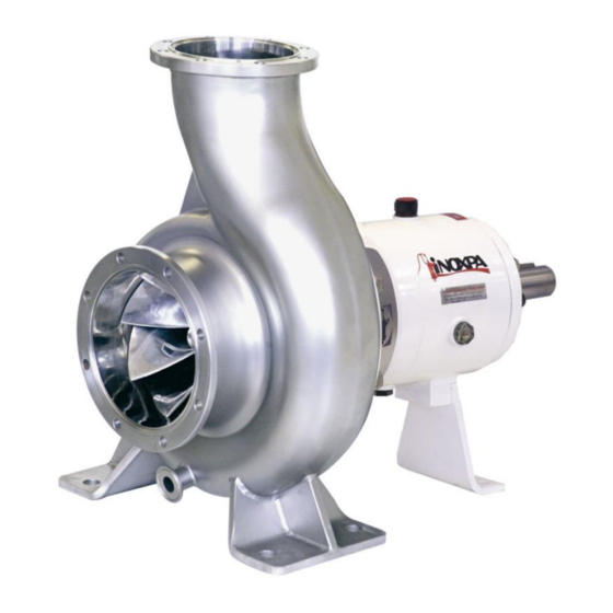
AISI 316L stainless steel, internal finish is n Ra 0.8. The DIN-FOOD centrifugal pump is built with a bare shaft or close-coupled construction with a shrouded motor, axial suction and radial discharge, connections with DIN-11864-2-B flanges. The impeller is of a half-open design with double curvature and manufactured in a single piece. - Page 8 Each pump has performance limits. The pump was selected for certain pumping conditions at the time the order was placed. INOXPA shall not be liable for any damage resulting from the incompleteness of the information provided by the purchaser (nature of the fluid, rpm, etc.).
-
Page 9: Installation
4. Installation 4.1. PUMP RECEPTION INOXPA cannot be held responsible for the damage sustained by the equipment during transport or unpacking. Visually check that the packaging is not damaged. The pump will be accompanied by the following documents: • Dispatch notes. -
Page 10: Location
4.3. LOCATION Place the pump as close as possible to the suction tank, and if possible below the product level. Technical Place the pump so as to allow sufficient space around it to access the pump and the motor. (See Chapter 8 Specifications for dimensions and weight). -
Page 11: Pipes
4.5. PIPES • As a general rule, the suction and delivery pipes should be fitted in straight sections, with the least possible number of bends and fittings, in order to minimise pressure loss caused by friction. • Ensure that pump inlet and outlet fittings are properly aligned with the piping and of a similar diameter to the pump connections. - Page 12 • Connect the motor following the manufacturer’s instructions. • Check the direction of rotation (see the label on the pump). Start up the pump motor briefly. Make sure, by looking at the pump from the rear, that the motor fan is rotating in a clockwise direction. ALWAYS check the direction of rotation of motor with fluid inside de pump.
-
Page 13: Start-Up
5.1. START-UP Technical Specification Read Chapter 8 thoroughly . INOXPA cannot be held responsible for the incorrect use of the equipment. NEVER touch the pump or the pipes when hot fluid is being pumped. 5.1.1. Checks before starting up the pump •... -
Page 14: Operating Problems
The following table provides solutions to problems that might arise during pump operation. The pump is assumed to have been properly installed and correctly selected for the application. Please contact INOXPA if technical assistance is required. Operating Problems Probable causes Motor overload 8, 9, 13, 14, 20, 21, 22, 23, 24. -
Page 15: Maintenance
7. Maintenance 7.1. GENERAL INFORMATION Like any other machine, this pump requires maintenance. The instructions contained in this manual cover the identification and replacement of spare parts. The instructions have been prepared for maintenance personnel and for those responsible for the supply of spare parts. -
Page 16: Cleaning
7.5. CLEANING The use of aggressive cleaning products such as caustic soda and nitric acid may cause burns to the skin. Use rubber gloves during the cleaning process. Always use protective goggles. 7.5.1. CIP process If the pump is installed in a system with a CIP process, it is not necessary to dismantle the pump. Assembly and Dismantling If there is no automatic cleaning process, dismantle the pump as indicated in the section. -
Page 17: Disassembly / Assembly Of The Pump
7.6. DISASSEMBLY / ASSEMBLY OF THE PUMP 7.6.1. Pump and impeller body Disassembly Remove the hexagonal screws (52) and washers (53) fixing the housing (01) to the lantern (04). Remove the blind nut (45) and O-ring (80D), then take out the impeller (02). Assembly Slide the impeller (02) over the shaft (05) until making contact with the spacer (17), attach the O-ring (80D) in the slot of the blind nut (45) and tighten the nut (45). - Page 18 7.6.2. Single mechanical seal Disassembly Remove the rotary part of the mechanical seal (08). Remove the screws (52E) fixing the cover (03) with the lantern (04). Remove the pump cover (03), the fixed part of the mechanical seal (08A) will remain housed inside the cap. Remove the fixed part of the mechanical seal (08).
- Page 19 7.6.3. Flushed mechanical seal (bare shaft) Disassembly Remove the rotary part of the mechanical seal (08). Remove the screws (52E) fixing the cover (03) with the lantern (04). Remove the pump cover (03) with the cap (10) and seal ring (30) still mounted. The fixed parts of the mechanical seals (08) and (08B) remain housed in the group.
- Page 20 7.6.4. Flushed mechanical seal (close-coupled, size 160 and 180 motors) Disassembly Remove the rotary part of the mechanical seal (08). Remove the screws (52E) fixing the cover (03) with the lantern (04). Remove the pump cover (03) with the cap (10) and seal ring (30) still mounted. The fixed parts of the mechanical seals (08) and (08B) remain housed in the group.
- Page 21 7.6.5. Flushed mechanical seal (close-coupled, size 200 motors) Disassembly Remove the rotary part of the mechanical seal (08). Remove the screws (52E) fixing the cover (03) with the lantern (04). Remove the pump cover (03) with the cap (10), back-cover (10A), and seal ring (30) still mounted. The fixed parts of the mechanical seals (08) and (08B) remain housed in the group.
- Page 22 7.6.6. Double mechanical seal (bare shaft) Disassembly Remove the spacer (17) together with the O-rings (80D). Remove the screws (52C) leaving the external cover loose (10B) with the fixed part of the external mechanical seal (08A) and the O-ring (80B). Remove the screws (52E) fixing the pump cover (03A) with the lantern (04).
- Page 23 7.6.7. Bearing support (bare shaft) Disassembly Remove the half coupling from the pump section and take out the key from the shaft end. Remove the rear foot (07) (if necessary) and the splash ring (82) from the pump side. Loosen the screws (52A) and the nuts (54) on the rear bearing cover (12) and uniformly tighten the cover extraction studs (55).
- Page 24 7.6.8. Adjusting the pump shaft Check that the shaft (05) assembly dimension in relation to the pump cover (03) is as indicated below: Pump type Ø D 315/400 315/400 If not, adjust the dimension until it is as indicated below. •...
-
Page 25: Technical Specifications
8. Technical Specifications 8.1. TECHNICAL SPECIFICATIONS 50Hz 60Hz Maximum flow ..............1000 m /h (4403 US GPM) 1000 m /h (4403 US GPM) Maximum differential head ............. 63 m (207 ft) 90 m (295 ft) Maximum working pressure ........... 10 bar (145 PSI) 10 bar (145 PSI) Operating temperature ............ -
Page 26: Din-Food Dimensions (Bare Shaft)
8.3. DIN-FOOD DIMENSIONS (BARE SHAFT) Flange dimensions DIN 11864-2-A -{}- PUMP TYPE 125-100-250 125-100-315 125-100-400 150-125-250 150-125-315 150-125-400 200-150-250 200-150-315 200-150-400 8.Maintenance 2021/11... -
Page 27: Din-Food Dimensions (Bare Shaft With Baseplate)
8.4. DIN-FOOD DIMENSIONS (BARE SHAFT WITH BASEPLATE) PUMP TYPE MOTOR DNa 1250 125-100-250 1290 1335 1330 1265 1305 150-125-250 1340 1345 1300 1020 1365 1330 1365 200-150-250 1335 1385 1405 1240 1280 125-100-315 1315 1385 1335 1355 1305 1350 1340... -
Page 28: Din-Food Dimensions (Close-Coupled)
8.5. DIN-FOOD DIMENSIONS (CLOSE-COUPLED) Flnge dimensions DIN 11864-2-A PUMP TYPE MOTOR DNa DNi m1 m2 125-100-250 125 100 121 160 120 360 260 440 350 415 470 150-125-250 150 125 128 200-150-250 200 150 142 1005 340 400 305 585 210 600 545 545 600 8.Maintenance... -
Page 29: Din-Food Dimensions (Shrouded Close-Coupled)
8.6. DIN-FOOD DIMENSIONS (SHROUDED CLOSE-COUPLED) Flange dimensions DIN 11864-2-A PUMP TYPE MOTOR DNa DNi 125-100-250 125 100 121 160 120 360 260 525 440 350 415 470 150-125-250 150 125 128 200-150-250 200 150 142 1105 340 400 305 690 210... -
Page 30: Din-Food Pump (Bare Shaft)
8.7. DIN-FOOD PUMP (BARE SHAFT) 8.Maintenance 2021/11... -
Page 31: Din-Food Pump (Close-Coupled)
8.8. DIN-FOOD PUMP (CLOSE-COUPLED) 2021/11 8.Maintenance... -
Page 32: Din-Food Pump (Bare Shaft) Cross-Section
8.9. DIN-FOOD PUMP (BARE SHAFT) CROSS-SECTION 8.Maintenance 2021/11... -
Page 33: Din-Food (Bare Shaft) Parts List
8.10. DIN-FOOD (BARE SHAFT) PARTS LIST Description Position Quantity Material Pump casing AISI 316L Impeller AISI 316L Pump cover AISI 316L Lantern GG-15 Shaft AISI 316L Bearings support GG-15 Rear leg GG-15 Mechanical seal Rear bearings cover F-114 Front bearings cover... -
Page 34: Din-Food Pump (Close-Coupled) Cross-Section
8.11. DIN-FOOD PUMP (CLOSE-COUPLED) CROSS-SECTION 8.Maintenance 2021/11... -
Page 35: Din-Food (Close-Coupled) Parts List
8.12. DIN-FOOD (CLOSE-COUPLED) PARTS LIST Description Position Quantity Material Casing AISI 316L Impeller AISI 316L Pump cover AISI 316L Lantern GG-15 Shaft AISI 316L Mechanical seal Bedplate AISI 304 Cap nut AISI 316L Lantern protector AISI 304 Screw Hexagonal screw... -
Page 36: Din-Food Flushed Mechanical Seal (Bare Shaft)
8.13. DIN-FOOD FLUSHED MECHANICAL SEAL (BARE SHAFT) Position Quantity Description Material Mechanical seal - rotary part - Mechanical seal - stationary part AISI 316L Cooled seal sleeve AISI 316L Cooled seal ring AISI 316L Hexagonal screw O-ring EPDM Connection elbow AISI 316 8.Maintenance... -
Page 37: Din-Food Flushed Mechanical Seal (Close-Coupled, Size 160 And 180 Motors)
8.14. DIN-FOOD FLUSHED MECHANICAL SEAL (CLOSE-COUPLED, SIZE 160 AND 180 MOTORS) Position Quantity Description Material Shaft AISI 316L Mechanical seal - rotary part - Mechanical seal – stationary part AISI 316L Cooled seal ring AISI 316L Hexagonal screw O-ring EPDM... -
Page 38: Din-Food Flushed Mechanical Seal (Close-Coupled, Size 200 Motors)
8.15. DIN-FOOD FLUSHED MECHANICAL SEAL (CLOSE-COUPLED, SIZE 200 MOTORS) Position Quantity Description Material Shaft AISI 316L Mechanical seal - rotary part - Mechanical seal – stationary part AISI 316L Cooled seal sleeve AISI 316L Cooled seal ring AISI 316L Allen screw... -
Page 39: Din-Food Double Mechanical Seal (Bare Shaft)
8.16. DIN-FOOD DOUBLE MECHANICAL SEAL (BARE SHAFT) Position Quantity Description Material Pump cover AISI 316L Shaft AISI 316L Internal mechanical seal External mechanical seal Double seal cap AISI 316L External cover AISI 316L Internal cover AISI 316L Spacer AISI 316L... - Page 40 Fax: 33 467 568 745 e-mail: frigail.fr@inoxpa.com npourtaud@inoxpa.com npourtaud.fr@inoxpa.com In addition to our branch offices, INOXPA operates with an independent distributor network which encompasses a total of more than 50 countries throughout the world. For more information consult our web page:...
Need help?
Do you have a question about the DIN-FOOD and is the answer not in the manual?
Questions and answers