sauter TU-US Instruction Manual
Ultrasonic material thickness gauge
Hide thumbs
Also See for TU-US:
- Instruction manual (12 pages) ,
- Operating instructions manual (35 pages)
Table of Contents
Advertisement
Quick Links
Advertisement
Table of Contents

Related Manuals for sauter TU-US


Summary of Contents for sauter TU-US
- Page 1 Sauter GmbH Ziegelei 1 Phone : +49-[0]7433- 9933-0 D-72336 Balingen Fax: +49-[0]7433-9933-149 e-mail: info@kern-sohn.com Internet: www.sauter.eu Instruction Manual Ultrasonic Material Thickness Gauge SAUTER TU-US Version 2.0 04/2020 PROFESSIONAL MEASURING TU_US-BA-e-2020...
-
Page 2: Table Of Contents
Gauge Congratulations on the purchase of an ultrasonic material thickness gauge from SAUTER. We hope you will enjoy your quality measuring device with its wide range of functions. Please do not hesitate to contact us if you have any questions, wishes or suggestions. - Page 3 Access to the main menu ...................... 19 Access to the submenu ......................19 Change the parameter......................19 Numerical digital input ......................19 Saving and exiting the menu ....................19 Deleting and exiting the menu ....................19 Maintenance ....................19 Transport and storage ................. 19 Annex ......................
-
Page 4: General Overview
1. General overview The model TU-US is a digital ultrasonic material thickness gauge. It is based on the same operating principles as SONAR. With the TU-US the material thickness of various materials can be measured with an accuracy of up to 0.01mm or 0.001 inch. It can be used for a variety of metallic and non-metallic materials. -
Page 5: Measuring Principle
1.3 Measuring principle The Ultrasonic Digital Material Thickness Gauge measures the thickness of a part or structure by accurately measuring the time taken for a short ultrasonic pulse to pass through the thickness of a material controlled by a probe, then reflected from the back or inner surface and returned to the probe. -
Page 6: Design Features
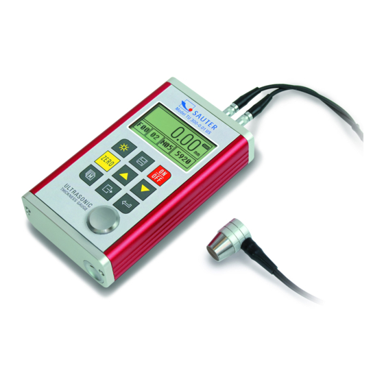
2. Design features 2.1 External device view 1= housing 2= measuring probe MT200 MiTec h 2.2 Parts of the main body 1 communication socket MT200 THICKNESS GAUGE 2 aluminium housing POWER: 2 X 1.5V OPERATION GUIDE 3 Belt mounting hole 1. -
Page 7: Description Of The Control Panel
• Pairing indicator: shows the pairing status; o This symbol must appear during measurements. If this is not the case, it is not possible to measure. • Operating display: shows whether the unit is switched on. • FIL: Group number •... -
Page 8: Preparation For Commissioning
4. Preparation for commissioning 4.1 Selection of the measuring probe With this device you can measure a wide range of materials, from various metals to glass and plastic. For different types of materials, different probes, i.e. US-measuring heads, are required. The correct probe is crucial for reliable measurement success. The following sections explain the important properties of the probe and what should be considered when selecting a probe for a specific work object. - Page 9 • The selection of the suitable measuring probe is often a compromise between different influences and properties. Sometimes it is necessary to try out several probes until the most suitable one is finally found for the respective test object. • The measuring probe is the "end piece '' of the measuring instrument. It transmits and receives ultrasonic waves, which the instrument uses to measure the thickness of the material to be examined.
-
Page 10: Conditions And Preparations For Surfaces
Model Freq Dia. Measuring range Lower limit Description ATU- For thick, highly 3.0mm~300.0mm(Stahl US01 damping ) highly scattering 40mm (cast iron) materials 1.2mm~230.0mm (steel) Φ20mm×3.0mm Normal ATU- US09 measurement Φ20mm×3.0mm Normal ATU- 1.2mm~230.0mm(Stahl US10 measurement ) /90° Φ15mm×2.0mm For ATU- thin 0.75mm~80.0mm US02... -
Page 11: Probe Selection
displayed before the measurement screen appears. The unit has a special memory in which all measurements are stored, even after the unit is switched off. 5.2 Probe selection The measuring probe must be "preset" before the measurement. This serves as an additional aid and enables the user to choose between the individual models the correct measuring probe for the measurement requirements (frequency and diameter dependent). -
Page 12: Speed Of Sound
Now the unit has detected the initial error factor and will use it to compare all subsequent measurements. When zeroing, the instrument will always use the sound velocity of the built-in zero plate, even if other values have been previously entered to make actual measurements. - Page 13 5.4.2 Calibration at known sound velocity Note: For this procedure, the sound velocity of the material to be measured must be known. A table of the most common materials can be found in Appendix A of this manual. 1. Press the key several times to move to the element "Speed of sound".
-
Page 14: Measurements Are Made
5.5 Measurements are made The meter always stores the last measured value until a new value is added. For the measuring probe to function properly, there must be no air bridges between its contact surface and the surface of the material to be measured. This is achieved with the ultrasonic gel, the "coupling agent". -
Page 15: Two-Point Calibration
5.6 Two-point calibration This procedure assumes that the user has two known material thickness points of the test material and that these are representative for the measuring range. 1. On the {Test Set} → {2- Point Cal} submenu, press the key to enable two- point calibration. -
Page 16: Resolution
1. In the {Test Set} → {Tolerance Limit} menu, press the key to activate the command. 2. Use the and keys to set the upper and lower limit value to the desired measured value. 3. The key is pressed again to confirm and enter the actual menu or the key is pressed to cancel the limit setting. -
Page 17: System Setup
5.11.2 Edit measured values Press the key repeatedly until the display shows {File name}. Use the and keys to change the group number. deletes the selected group deletes all groups marks the selected group to save to it Leave dialogue Press the key repeatedly until the display shows {Record count}. -
Page 18: System Information
5.13 System information This function gives the main information about the main body of the machine and the firmware. The design changes when the firmware changes. 5.14 Backlit display This allows it to be used in dark environments. The key is used to activate and deactivate the backlight once the meter has been switched on. -
Page 19: Connection To Pc
If the unit is not used for a long period of time, the batteries should be removed. It is recommended to replace the batteries already when the capacity is down to 10%. 5.18 Connection to PC The unit is equipped with USB 2.0 as standard. With the optional available cable the connection to the PC is possible. -
Page 20: Annex
9. Annex 9.1 Sound velocities Material Sound Velocity In/us Aluminum 0.250 6340-6400 0.233 Conventional. Steel 5920 0.226 Stainless steel 5740 Brass 0.173 4399 Copper 0.186 4720 Iron 0.233 5930 Cast Iron 0.173-0.229 4400-5820 Lead 0.094 2400 Nylon 0.105 2680 Silver 0.142 3607 Gold... -
Page 21: Remarks On Application
9.2 Remarks on application 9.2.1 Measuring tubes and hose material If a piece of pipe is measured to determine the thickness of the pipe wall, the positioning of the measuring probe is important. If the diameter of the pipe is larger than 4 inches, the position of the probe on the pipe should be such that the incision on the contact surface is perpendicular to the long axis of the pipe. -
Page 22: Measuring Coated Materials
9.4 Measuring coated materials Coated materials are special because their density (and therefore the speed of sound) can vary considerably from one piece to another. Even through a single surface, noticeable differences in the speed of sound can be detected. The only way to obtain an accurate measurement result is to first perform a calibration on a material sample of known material thickness.
Need help?
Do you have a question about the TU-US and is the answer not in the manual?
Questions and answers