sauter TU 80-0.01US Instruction Manual
Tu-us series digital ultrasonic thickness gauge
Hide thumbs
Also See for TU 80-0.01US:
- Instruction manual (22 pages) ,
- Operating instructions manual (35 pages)
Table of Contents
Advertisement
Quick Links
Advertisement
Table of Contents

Related Manuals for sauter TU 80-0.01US


Summary of Contents for sauter TU 80-0.01US
- Page 1 Sauter GmbH Ziegelei 1 Tel: +49-[0]7433- 9933-199 D-72336 Balingen Fax: +49-[0]7433-9933-149 E-Mail: info@sauter.eu Internet: www.sauter.eu Instruction Manual Digital Ultrasonic Thickness Gauge SAUTER TU-US Version 1.4 09/2017 PROFESSIONAL MEASURING TU_US-BA-e-1714...
-
Page 2: Table Of Contents
Instruction Manual Digital Ultrasonic Thickness Gauge Thank you for buying a digital SAUTER Material Thickness Gauge. We hope you are pleased with your high quality instrument and with its big functional range. If you have any queries, wishes or helpful suggestions, do not hesitate to call our service number. - Page 3 4.18 System reset ................Fehler! Textmarke nicht definiert. 4.19 Connection to PC ........................19 Menu operation .................... 19 Enter the main menu ......................19 Enter the Sub menu ........................ 19 Change the parameter......................19 Numeric digit input ......................... 19 Save and exit ........................... 20 Cancel and exit ........................
-
Page 4: Overview
1 Overview The Model TU-US is a digital ultrasonic thickness gauge. Based on the operating principles as SONAR, it is capable of measuring the thick- ness of various materials with an accuracy as high as 0.01 mm (or 0.001 inches). It is suitable for a variety of metallic and non-metallic materials. -
Page 5: Main Functions
1.2 Main functions Capable of performing measurements on a wide range of materials including met- als, plastic, ceramics, epoxies, glass and other ultrasonic wave well- conductive materials. Four transducer models are available for special applications included coarse grain material and high temperature applications. Zero adjustment function Sound velocity calibration function Two- point calibration function... -
Page 6: Configuration
1.4 Configuration Item Quan- Note tity Standard Main body Configuration Transducer ATU-US10 90° Couplant Instrument Case Operating Manual Screwdriver Alkaline battery AA size Optional Con-fig- Transducer: ATU-US01 See Table3-1 uration Transducer: ATU-US02 Transducer: ATB-US02 DataPro for Thickness For use on the Gauge Communication Cable 1.5 Operation conditions... -
Page 7: Parts Of The Main Body
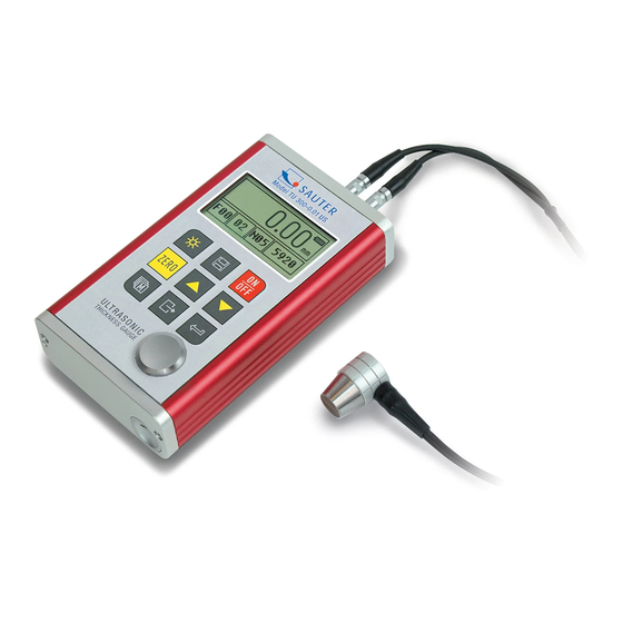
2.2 Parts of the main body 1 Communication Socket 2 Aluminium case MT200 THICKNESS GAUGE 3 Belt hole POWER: 2 X 1.5V OPERATION GUIDE 4 Battery cover 1. Plug in the transducer Power On/Off 5 Keypad Backlight On/Off Probe Zero 6 LCD Display Switch Selection Save/Delete... -
Page 8: Keypad Definitions
SCA: Indicates that the current thickness measurement Mode is Scan mode, not Single point mode. File name: current file name is shown Record No./ Count: The current record number is indicated while this item is highlighted or the total record counts while it isn’t highlighted. Transducer Model: Current transducer model setting in the instrument o ATU-US01: N02 o ATB-US06: N05... - Page 9 transducer for an operation is the one that sends sufficient ultrasonic energy into the material to be measured in the way that a strong, stable echo is to be received in the instrument. There are several factors that affect the strength of the traveling ultra- sound.
-
Page 10: Conditions And Preparation Of Surfaces
The upper figure is a bottom view of a typical transducer. The two semicircles are visibly separated in the middle of the surface. One of the semicircles is conducting the echoed sound back into the transducer. When the transducer is placed against the material being measured, this is the area directly beneath the centre of the measured surface. -
Page 11: Operation
The surface being measured should be clean and free of any small particulate matter, rust or scale. The transducer must be placed on a flat and even surface. To get it clean it might be helpful to use a wire brush or a scraper. In more extreme cases, rotary sanders or grinding wheels may be used. -
Page 12: Zero Adjustment
5.3 Zero adjustment key is used to „zero“ the instrument. It is just the same way as a mechanical micrometer is zeroed. If the instrument isn’t zeroed correctly, all the measurements taken may be in error by an initially incorrect value. When the instrument is zeroed, this fixed error value is measured and automatically corrected for all subsequent meas- urements. -
Page 13: Calibration To A Known Thickness
Note: One- and Two-point calibrations should only be performed on material where the paint or the coating is removed; if not, it will result in a multi material velocity cal- culation which is surely deviating from the actual velocity of the material intended to be measured. -
Page 14: How To Perform Measurements
2) The key has to be pressed multiple times to tab to the numeric digit to be changed. keys have to be used to increase/ decrease numeric values on the display until the sound velocity of the material being measured is matched. An auto repeat function is built in, so that when the key is held down, numeric values will increment/ decrement at an increasing rate. -
Page 15: Two-Point Calibration
In addition, measurements performed through very thick paint or coatings may result in the paint or coating being measured rather than the material intended. The responsibility for a proper use of the instrument, as well as the recognition of these types of phenomenon solely depends on the user of this instrument. -
Page 16: Limit Set
On the 【Test Set】->【Work mode】menu item the key has to be pressed to toggle between single point mode and scan mode. 5.8 Limit set With the Limit set feature the user is able to set an audible and visual parameter while taking measurements. -
Page 17: Memory Management
5.11 Memory management 5.11.1 Storing a reading There are 100 files (F00-F99) which can be used to store the measurement values inside the instrument. At most 100 records can be stored in each file. The following steps outline how to do this: 1) The key has to be pressed to activate the 【File Name】item on the main measurement screen. -
Page 18: System Set
5.12 System Set key has to be pressed on the 【System set 】menu item and enter this submenu from the main menu. 1) When 【Auto save 】is set to <On>, the measured data are automatically stored to the current file. 2) When 【Key sound 】is set to <On>, the buzzer will make a short hoot every time if any key is pressed. -
Page 19: Tu_Us-Ba-E
If battery capacity runs out, the battery symbol will be shown and it will begin to flash. In this case, the batteries should be replaced. If the instrument isn’t used for a longer period, the batteries have to be removed. Anode MT200 Procedure:... -
Page 20: Save And Exit
key has to be pressed multiple times to tab to the numeric digit to be changed; the numeric values on the display can be decreased/ increased with the key until the desired value is matched. 6.5 Save and exit key has to be pressed to confirm the modification and to return back to the previous screen. - Page 21 Appendix A Sound velocities Material Sound Velocity In/us Aluminum 0.250 6340-6400 0.233 Herkömml. Stahl 5920 0.226 Rostfreier Edelstahl 5740 Messing 0.173 4399 0.186 Kupfer 4720 Eisen 0.233 5930 Gusseisen 0.173-0.229 4400- 5820 0.094 Blei 2400 Nylon 0.105 2680 Silber 0.142 3607 Gold 0.128...
- Page 22 Measuring hot surfaces The sound velocity through a substance is dependent on its temperature. As materials heat up, the velocity of sound through them decreases. In most applications with sur- face temperatures of less than 100°C, no special procedures must be observed. At temperatures above that point, the change in sound velocity of the material being measured starts having a noticeable effect upon ultrasonic measurement.
- Page 23 Coupling medium Every ultrasonic application requires some medium to couple the sound from the trans- ducer to the tested material. Typically, a high viscosity liquid is used as the medium. The sound used in ultrasonic thickness measurement doesn’t travel through air effi- ciently.
Need help?
Do you have a question about the TU 80-0.01US and is the answer not in the manual?
Questions and answers