Table of Contents
Advertisement
Quick Links
Advertisement
Table of Contents

Related Manuals for sauter TE 1250-0.1F


Summary of Contents for sauter TE 1250-0.1F
- Page 1 Sauter GmbH Ziegelei 1 Phone : +49-[0]7433- 9933-0 D-72336 Balingen Fax: +49-[0]7433-9933-149 e-mail: info@kern-sohn.com Internet: www.sauter.eu Instruction Manual Digital Coating Thickness Gauge SAUTER TE Version 2.0 04/2020 PROFESSIONAL MEASURING TE-BA-e-2020...
-
Page 2: Table Of Contents
Instruction Manual Digital Coating Thickness Gauge Thank you for purchasing a digital coating thickness gauge from SAUTER. We hope you will be very satisfied with the high quality of this measuring device and its extensive functionality. For any questions, wishes and suggestions please do not hesitate to contact us. -
Page 3: Introduction
"The backlit display allows accurate reading " Can be connected to a PC for data transfer via RS 232 interface for statistical purposes. Cable and software are available as optional accessories (ATC-01). 3. Technical data TE 1250-0.1F TE 1250-0.1FN TE 1250-0.1N Display 4 digits, 10mm LCD display with backlight 0 to 1250 μm / 0 to 50 mil (standard) - Page 4 - 1 set of adjustment foils, available for each model - Zero plate (aluminium) for TE 1250-0.1N and TE 1250-0.1FN - Zero plate (iron) TE 1250-0.1F and for TE 1250- 0.1FN - Optional accessories: Software and cable RS- 232C: ATC-01, AFH 12 (RS 232 to USB adapter)
-
Page 5: Description Of The Control Panel
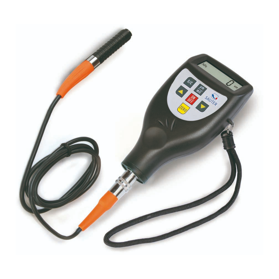
4. Description of the control panel 4-10 here: Model TE-1250-0.1FN 4- 1 Measuring probe 4- 2 Display 4- 3 Zero key 4- 4 Plus button 4- 5 Minus key 4- 6 On/off button (multifunctional) 4- 7 µm/ mil Changeover key (shortcut key) 4- 8 Battery compartment / rear cover 4- 9 Connector for RS-232C connection 4-10 S/C measuring mode button (single/continuous) -
Page 6: Adjustment
5.4 To take the next measurement, simply add more is raised by 1cm, the display shows "0" again and step 4.3 is repeated. 5.5 In case of possible inaccuracies in the measurement result, it is recommended to adjust the measuring instrument before the measurement as described in chapter 6. 5.6 The device can be switched off with the on/off button. -
Page 7: Battery Replacement
6.5 Step 6.4 is repeated until the desired measuring accuracy is achieved. 7. Battery replacement 7.1 When the battery symbol appears on the display, the batteries should be replaced. 7.2 The battery cover 4-8 is removed from the meter and the batteries are removed. 7.3 The batteries (4x1.5V AAA/UM-4) are inserted by observing the polarity when inserting them. -
Page 8: 10. General Notes
10. General notes 10.1 The measuring instrument should always be adjusted on the base material used for the actual measurement, instead of on the supplied zero plate. This ensures that the measuring accuracy is more accurate from the outset. 10.2 The measuring probe may wear out. The service life of the measuring probe usually depends on the number of measurements and the roughness of the layer to be measured. - Page 9 In general, the larger the LN value, the smaller the reading result for the same layer thickness. A small change in the LN value causes a large change in the reading result in the upper measuring range (at 500µm/ 20mil). The LN value must be corrected in this way: Pressing the on/off button: It takes about 11 seconds from the start of pressing this button.
Need help?
Do you have a question about the TE 1250-0.1F and is the answer not in the manual?
Questions and answers