Table of Contents
Advertisement
Quick Links
Sauter GmbH
Ziegelei 1
D-72336 Balingen
E-Mail: info@sauter.eu
Instruction Manual
Multi Mode
Ultrasonic Thickness Gauge
SAUTER TN-EE
Version 1.1
02/2014
GB
Tel: +49-[0]7433- 9933-199
Fax: +49-[0]7433-9933-149
Internet: www.sauter.eu
Importør:
Impex Produkter AS
Gamle Drammensvei 107
1363 HØVIK
Tel. 22 32 77 20
info@impex.no
www.impex.no
TN_EE -BA-e-1411
Advertisement
Table of Contents

Related Manuals for sauter TN-EE


Summary of Contents for sauter TN-EE
- Page 1 Tel: +49-[0]7433- 9933-199 D-72336 Balingen Fax: +49-[0]7433-9933-149 E-Mail: info@sauter.eu Internet: www.sauter.eu Instruction Manual Importør: Impex Produkter AS Multi Mode Gamle Drammensvei 107 Ultrasonic Thickness Gauge 1363 HØVIK Tel. 22 32 77 20 info@impex.no www.impex.no SAUTER TN-EE Version 1.1 02/2014 TN_EE -BA-e-1411...
-
Page 2: Table Of Contents
Version 1.1 02/2014 Instruction Manual Ultrasonic Thickness Gauge Thank you for buying a SAUTER Material Thickness Gauge. We hope you are pleased with your high quality instrument and with its big functional range. If you have any queries, wishes or helpful suggestions, do not hesitate to call our service number. -
Page 3: Overview
1 Overview The model TN-EE is a multi-mode ultrasonic thickness gauge. Based on the same operating principles as SONAR, the instrument is capable of measuring the thickness of various materials with accuracy as high as 0.1/0.01 millimeters. The multi-mode feature of the gauge allows the user to toggle between pulse-echo mode and echo-echo mode (eliminating paint or coating thickness). -
Page 4: Measuring Principle
1.3 Measuring Principle The digital ultrasonic thickness gauge determines the thickness of a part or structure by accurately measuring the time required for a short ultrasonic pulse generated by a transducer to travel through the thickness of the material, reflect from the back or in- side surface, and be returned to the transducer. -
Page 5: Keypad & Screen
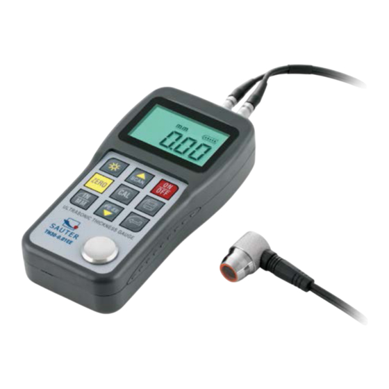
2 Keypad & Screen Explanation: 1 The main body 2 Keypad 3 LCD display 4 Pulse socket ULTRASONIC THICKNESS GAUGE 5 Receiver socket POWER: 2 X 1.5V 6 Sensor zero disc 1. 2.1 Main Screen 7 Communication port 8 Label 9 Battery cover 10 Measurement head Explanation:... -
Page 6: Preparation
Unit switch Minus; tween Metric and Switch between Imperial system pulse-echo and echo-echo mode Data Save or Da- ta Delete 3 Preparation 3.1 Transducer Selection The gauge is inherently capable of performing measurements on a wide range of ma- terials, from various metals to glass and plastics. Different types of material, however, will require the use of different transducers. -
Page 7: Condition And Preparation Of Surfaces
The transducer is the “business end” of the instrument. It transmits and receives ul- trasonic sound waves that the instrument uses to calculate the thickness of the mate- rial being measured. The transducer connects to the instrument via the attached ca- ble, and two coaxial connectors. -
Page 8: Operation
perpendicular to the material surface. In this case, it will be difficult to exactly locate tiny irregularities in the material being measured, as the focus of the sound beam no longer lies directly beneath the transducer. 4 Operation 4.1 Power On/Off The instrument is turned on by pressing the key. -
Page 9: Sound Velocity Calibration
3) Use the key and the key to scroll to the probe model currently being used. Be sure to set the right probe model to the instrument. Otherwise, there will be er- rors or deviations. 4) Apply a single droplet of ultrasonic couplant to the face of the metal probe disc. 5) Press the transducer against the probe disc, making sure that the transducer sits flat against the surface. -
Page 10: Calibration To A Known Velocity
7) Press the key again. The M/S (or IN/μS) symbols should begin flashing. The gauge is now displaying the sound velocity value it has calculated based on the thickness value that was entered. 8) Press the key once again to exit the calibration mode and return to the meas- urement mode. -
Page 11: Performing Measurements
4.5 Performing Measurements When the instrument is displaying thickness measurements, the display will hold the last value measured, until a new measurement is made. In order for the transducer to do its job, there must be no air gaps between the wear- face and the surface of the material being measured. -
Page 12: Changing Resolution
When the scan mode is turned off, the single point mode will be automatically turned on. Turn on/off the scan mode by the following steps: Press the key to switch the scan mode on and off. It will display the current condi- tion of the scan mode on the main screen. -
Page 13: El Backlight
3. Press the key to enter the selected file. It will display the current record num- ber (for example, L012) and the record content. 4. Use the key and the key to select the desired record. 5. Press the key on the desired record. It will automatically delete this record, and display “-DEL”. -
Page 14: Transport And Storage
6 Transport and Storage Keep it away from vibration, strong magnetic field, corrosive medium and dust. Storage in ordinary temperature. Appendix A: Applications Notes Measuring pipes and tubes When measuring a piece of pipe to determine the thickness of the pipe wall, orienta- tion of the transducers is important. - Page 15 these. In echo-echo mode, the paint/ coating thickness will be eliminated entirely and the steel will be the only material measured. Suitability of materials Ultrasonic thickness measurements rely on passing a sound wave through the mate- rial being measured. Not all materials are good at transmitting sound. Ultrasonic thickness measurement is practical in a wide variety of materials including metals, plastics, and glass.
-
Page 16: Declaration Of Conformity
EN 50082-2 2004 / 108 EC Datum 07.04.2009 Signatur Date Signature Ort der Ausstellung 72336 Balingen Albert Sauter Place of issue SAUTER GmbH Geschäftsführer Managing director SAUTER GmbH, Ziegelei 1, D-72336 Balingen, Tel. +49-[0]7433/9933-199 Fax +49-[0]7433/9933-149, E-Mail: info@sauter.eu, Internet: www.sauter.eu TN_EE-BA-e-1411...
Need help?
Do you have a question about the TN-EE and is the answer not in the manual?
Questions and answers