Table of Contents
Advertisement
Quick Links
Advertisement
Table of Contents

Related Manuals for SICK Mounting kit 2


Summary of Contents for SICK Mounting kit 2
- Page 1 M o u n t i n g k i t 2...
- Page 2 Mounting instructions Mounting kit 2 This document is protected by copyright. The SICK AG company retains this right. Reproducing this document in whole or part is only permissible within the limits of the statutory regulations of copyright law. Modifying or abridging the document is impermissible without the express written permission of from the SICK AG company.
-
Page 3: Table Of Contents
2.3.4 Mounting vertical adjusting arms in the cross adapter........9 2.3.5 Applying latching marks....................10 2.3.6 Mounting cables......................11 2.4 Mounting on the side of the press crosshead ..............13 8 011 148/14-04-05 • SICK AG • Industrial Safety Systems • Deutschland • All rights reserved... -
Page 4: Product Description
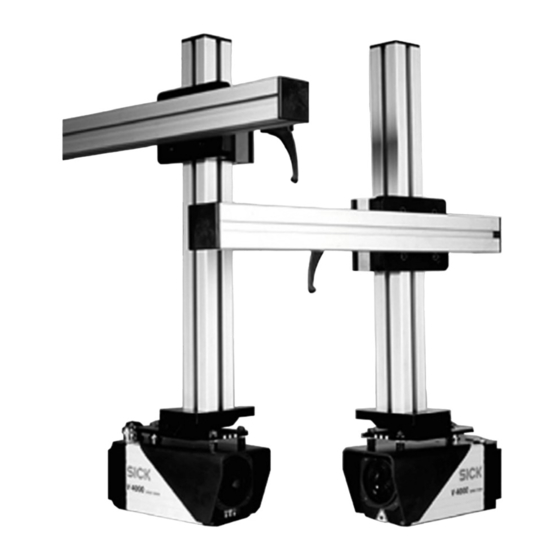
Mounting kit 2 Product description The retaining device for the V 4000 Press Brake sensor (SICK mounting kit 2) consists of a vertical adjusting arm, an adapter plate with groove for accommodating the sliding nut (SICK mounting kit 1) and a horizontal adjusting arm that is mounted to the press crosshead. -
Page 5: Mounting
If this alternative is used, approx. 0.5 m clearance is required at both sides of the press. Fig. 1: Mounting on the rear of the press crosshead 8 011 148/14-04-05 • SICK AG • Industrial Safety Systems • Deutschland • All rights reserved... - Page 6 This alternative requires little clearance in the width. Fig. 2: Mounting on the side of the press crosshead • SICK AG • Industrial Safety Systems • Deutschland • Al rights reserved 8 011 148/14-04-05...
-
Page 7: Mounting On The Rear Of The Press Crosshead
Premounting vertical adjusting arms on the left/right Notes The SICK mounting kit 2 is supplied in two packages. One package contains all the components required to mount the retaining device onto one side of the press crosshead. The vertical adjusting arm is premounted for the left-hand mounting side. For mounting on the right-hand side the adjusting arm has to be modified. -
Page 8: Premounting Horizontal Adjusting Arms On The Left/Right
25 mm in depth) from behind into the press crosshead (1). Cut a thread M12, min. 20 mm deep. Blow out the thread hole clean. • SICK AG • Industrial Safety Systems • Deutschland • Al rights reserved 8 011 148/14-04-05... -
Page 9: Mounting Vertical Adjusting Arms In The Cross Adapter
Pull the stop bolt and slide the vertical adjusting arm from below into the cross adapter. The groove of the adapter plate (2) points away from the press crosshead. 8 011 148/14-04-05 • SICK AG • Industrial Safety Systems • Deutschland • All rights reserved... -
Page 10: Applying Latching Marks
V 4000 Press Brake sensor rapidly in case of frequent tool changes. One grid hole (1) exists. Drill further holes (Ø 6.3 mm) in accordance with the tool lengths that are often used. • SICK AG • Industrial Safety Systems • Deutschland • Al rights reserved 8 011 148/14-04-05... -
Page 11: Mounting Cables
On the receiver end push the cable protection tube (3) from below over the cable (2) until the cable protection tube projects 7 cm into the adjusting arm (1). 8 011 148/14-04-05 • SICK AG • Industrial Safety Systems • Deutschland • All rights reserved... - Page 12 Insert the 3 missing screws at each of the adapter plates and tighten all the screws. Fastening the cable protection tube Fig. 12: Fastening the cable protection tube (view of receiver end) • SICK AG • Industrial Safety Systems • Deutschland • Al rights reserved 8 011 148/14-04-05...
-
Page 13: Mounting On The Side Of The Press Crosshead
Pull the stop bolt and slide the adjusting arm (6) into the cross adapter. Ensure that you use the adjusting arm that is suitable for the mounting side. Mount the cables (see Section 2.3.6 on Page 10). 8 011 148/14-04-05 • SICK AG • Industrial Safety Systems • Deutschland • All rights reserved... - Page 14 N e d e r l a n d s More representatives and agencies Phone +31 (0)30 229 25 44 in all major industrial nations at E-Mail info@sick.nl www.sick.com SICK AG • Industrial Safety Systems • Waldkirch • Germany • www.sick.com...
Need help?
Do you have a question about the Mounting kit 2 and is the answer not in the manual?
Questions and answers