Table of Contents
Advertisement
Quick Links
FLEX 32 Quick Start
● Fully Modular 32×32 signal architecture
● Mixed signal matrix switching
● Up to 32 mega pixels output splicing
● Auto switch input
● Load and save up to 256 presets
● Output resolution up to 2048x1152@60Hz / 2560x816@60Hz
● EDID management
● Remote control by XPOSE and RGBlink OpenAPI
Advertisement
Table of Contents

Related Manuals for RGBlink FLEX 32


Summary of Contents for RGBlink FLEX 32
- Page 1 ● Mixed signal matrix switching ● Up to 32 mega pixels output splicing ● Auto switch input ● Load and save up to 256 presets ● Output resolution up to 2048x1152@60Hz / 2560x816@60Hz ● EDID management ● Remote control by XPOSE and RGBlink OpenAPI...
-
Page 2: Table Of Contents
CONTENTS Product Introduction.............................. 3 Hardware Orientation............................5 Basic Front Panel............................5 Matrix Front Panel............................6 Rear Panel................................ 7 Matrix Front Panel Operation..........................9 MENU Operation............................9 Button Operation............................11 Software Operation.............................. 14 Install Software.............................14 Login to the Software...........................17 Connect to Software............................. 18 Output Setting...............................21 Output setting............................ -
Page 3: Product Introduction
Different devices can be connected in each output and input. It supports HDMI, DVI, SDI, USB and HDBaseT input and output signals, as well as DP output. FLEX 32 features in splitting mode for up to 2K1K, and simple managed by XPOSE software. - Page 4 In The Box AC Power Cable Ethernet Cable Note: AC Power Cable supplied as standard according to destination market. 4/30...
-
Page 5: Hardware Orientation
Hardware Orientation Basic Front Panel Basic front panel fit for FLEX series: Panel Instruction USB INTERFACE To POWER BUTTON upgrade the device Turn on/off button. Indicator lights when the device is powered up or in standby state. Power Indicator Lan Indicator Light up when device Lights up when LAN power on... -
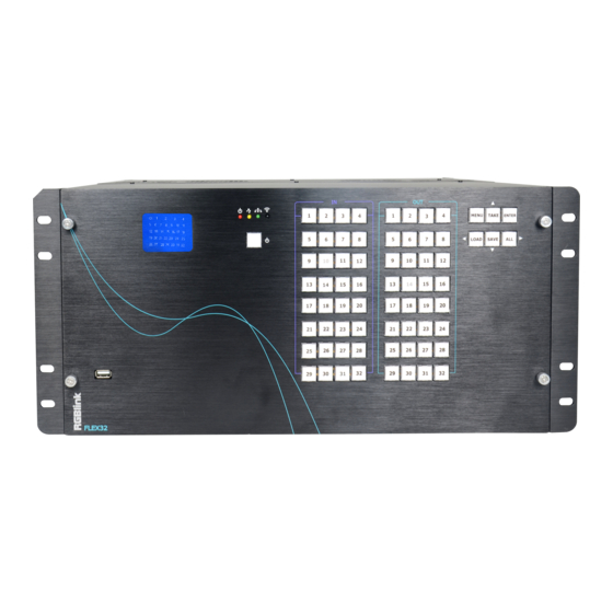
Page 6: Matrix Front Panel
Matrix Front Panel Matrix front panel fit for Flex series as an option. Panel Instruction USB INTERFACE To POWER BUTTON upgrade the device Turn on/off button. Indicator lights when the device is powered up or in standby state. Power Indicator Lan Indicator Light up when device Lights up when LAN... -
Page 7: Rear Panel
Save Button, to save Choose all inputs or all current settings to pages. outputs for matrix mode Input signal source Output signal selection selection button under button under matrix matrix mode mode LCD display Rear Panel Input Interface Input Card Slots Supports input signals including HDMI, DVI, SDI, USB and HDBaseT. - Page 8 Output Card Slots Supports output signals including HDMI, DVI, SDI, USB, HDBaseT and Control Interface Communication Ports RS232&LAN Connect to XPOSE software Power Connection Power Socket-IEC 8/30...
-
Page 9: Matrix Front Panel Operation
Matrix Front Panel Operation MENU Operation Menu Structure Basic Operation Press MENU button and enter the MENU item →STATUS 》 RESET 》 USE the buttons with arrows of up left right down direction to select. 3.Press ENTER to enter the selected menu item. STATUS Shows : the status of each input to output and the LCD screen shows the exact info, as following example In→Out,... - Page 10 RESET To go back to the beginning status, in the RESET item, LCD screens shows instruction as follow PRESSS ANY KEY PRESS MENU TO EXTIT LOGO Display logo ON/OFF LOGO DISP →ON LANGUAGE To switch language between Chinese and English LANGUAGE/语言...
-
Page 11: Button Operation
Button Operation Power Up After the device is connect to power, it will automatically boot up. After the device is powered up LCD shows the following: O:123456789ABCDEFG I : 123456789ABCDEFG Select output Press any button among 1-32 in OUT area, the corresponding output can be selected and the button light illuminates. - Page 12 Press button ALL and all buttons in OUT area light up, then press any button in IN area, all outputs display the one selected input. For example, after pressing button ALL and press button 6 in IN area, all the displays shows the image of input 6. The LCD on device shows the info below: O:123456789ABCDEFG I : 666666666666666666...
- Page 13 In stand by mode, press POWER for 3S, all buttons flashes one by one immediately and LCD shows RGBLINK FLEX 32 5S later, the device goes back to work and in the status before stand by. 13/30...
-
Page 14: Software Operation
Software Operation Install Software Minimum Requirements XPOSE Version 1.2.7.0 Windows Operation System Windows 7/8/10 Processor 1GHz/32 bit or 64 bit processor Memory Hard Disk 16Gb Graphics 128Mb/DirectX9 Display 1280X720 Operation System Mac OS Processor 1.0GHz+ Memory 512M+ Hard Disk 512M+ Graphics 512M+ Display... - Page 15 1. Double click icon , it will pop-up the Installer Language box, select the language, for example, select “English”, and click “OK” to confirm. It will pop-up the installer box, and click “Next” to install, as follows: 2. Select “Browse...” to select the XPOSE software install location and click install: 15/30...
- Page 16 3. User should get the rights in “Roles Management” when install the software to disk C if the system is Windows 7 or above. 4. Click “Finish” and is ready to run the XPOSE management software: 16/30...
-
Page 17: Login To The Software
The user name is Admin, and defaultly there is no password. Select “FLEX 16”, as there is no FLEX 32 in the drop down list, select language “English” and enter the software by clicking “Login”. -
Page 18: Connect To Software
XPOSE management software consists of Output Setting,Operation Mode, System Settings and Log out. In the following parts come with the detail. Connect to Software Connect the remote controller PC which runs XPOSE to FLEX 32 by the network cable In The Box or USB A-B cable. Click search... - Page 19 and get the device to XPOSE After Sync, enter the following interface. 19/30...
- Page 20 Close the current interface, just click the X on the right top corner and enter the main menu interface. 20/30...
-
Page 21: Output Setting
Output Setting Click Output setting and enter the interface as below: 21/30... -
Page 22: Output Setting
Output setting choose output resolution here There are 28 standard resolution format available and users can chose custom the output resolution by choose “Custom ” and type in the Custom Width. Height and Frequency. User can custom the resolution if no proper resolution in the list, SDI Output cannot display either USB input or DVI input (... -
Page 23: De Setting
EXT 4F-OM 2560×816@60Hz and 2048×1152@60Hz , not supported on DVI and HDMI output) Then click Setting to confirm. DE Setting Board Type: select EXT-6 (EXT4F-OS) or EXT-4 (EXT4F-OM) based on the real installation of the device. Out/In: Output setting or Input setting Port:Port1-Port 8 to choose Output Type:DVI or HDMI Color Range:Image or Video... -
Page 24: Operation Mode
Operation Mode There are 2 working modes, including the Matrix mode and Splitting Mode. Click the “Operation Mode”, and enter the interface as follows: Matrix Mode and Splitting Mode are included in operation mode, specific as follows: Matrix Mode Click the “Matrix Mode”, and enter to the interface as follows: In→Out 24/30... - Page 25 3. Click Take 4. The display will show the input source correspondingly as the following show: For FLEX 32 with matrix front panel, users can use XPOSE or front panel panel to control the device. For FLEX 32 with basic front panel, users can only use XPOSE to control.
- Page 26 Click Take All display will show the one chosen input source as the following show: SDI Output cannot display either USB input or DVI input ( including compatible YPbPr, CVBS,VGA ) when it is installed on EXT4F-OM Output Card Click each output port, users can set output resolution of each port 26/30...
-
Page 27: Splitting Mode
Choose Advance, scale and crop setting can be done. Splitting Mode Click the “Splitting Mode”, and pop-up window as follow: 27/30... - Page 28 To do quick splitting, users can choose signal from signal list and drag it to the window. Drag the border of the layer to cover all the monitors. For example, do splitting on 4 monitors, after setting the resolution of each output, drag the input source to the output window and cover up all outputs.
- Page 29 It displays the input module type, the quantity of inputs and input format. Click”... “afer the format of input for the following settings: For HDMI and SDI input there are settings as below: Change Name: Select “New Name”, and input the new name, click “OK” after setting. Set Input Property: Right click the input and select “Input Property”, it will enter to the interface as follows: Scale: Set the X, Y, width and height.
- Page 30 Crop: Crop the left, top, width and height. Display Mode: Select “Live” or “Freeze”. Mirror: Enable or disable the mirror function, default “OFF”. Bypass Mode: Enable or disable the bypass mode. When select “ON”, the output format will be the same with the input format. Alpha: Set the alpha, the adjustment range is 0~128.
- Page 31 USB picture player setting: Can select play in order, random, single cycle and all cycle, and switch to pre or next, pause or play. DVI module of FLEX 32 is compatible with VGA,CVBS, YPbPr signals via adapter , therefore for other signal such as VGA input, users need to choose VGA in DVI input...
- Page 32 Output Setting Click on shortcut , it will enter the interface as follows: Close monitor: Click the icon on the top right corner of the monitor to close one monitor, or click the shortcut on the right side of the interface to close all monitors.
- Page 33 Auto tile: User can enable or disable the auto tile function by clicking the auto tile shortcut on the right side of the interface. If select auto tile “ON’, the layer will automatically snap to the output grid when move the layer to the position within the threshold value.
- Page 34 Rotation: Select the monitor, and set the rotation as 0°, 90°, 180° and 270° in the bottom of the interface. Click “OK” to confirm. As shown in the figure below: Note: select any 1 out of the 4 outputs which are connected to the same EXT extension interface.
- Page 35 Set TP OK Adjust Layer: Two ways can change the size and location of the opened layer: a. Drag the opened layer by mouse. The details are: move the mouse to the brink of the opened layer, when the mouse shows”<—>”, press the left key of the mouse and drag the window to a suitable size and then release the mouse.
- Page 36 Close one layer or all layers: Click the icon on the top right corner of the layer to close one layer, or click the shortcut key “ ” to close all layers. Lock the layer: Click the icon on the top right corner of the layer to lock the layer, the layer can’t be moved or adjusted if be locked.
- Page 37 Bypass Mode: Enable or disable the bypass mode. When select “ON”, the output format will be the same with the input format. Alpha: Set the alpha, the adjustment range is 0~128. Sharpness: Set the sharpness, the adjustment range is 0~100. Brightness: Set the brightness, the adjustment range is 0~100.
- Page 38 Loop Click the loop shortcut “ ”, and pop-up window as follows: Timing Loop Slide the loop switch to enable or disable the timing loop function for the bank. If select “ON”, the exact time to play the bank can be set. Times Loop Slide the loop switch to enable or disable the times loop function for the bank.
- Page 39 Sync Click the sync shortcut “ ” to synchronize the current data. Load Script Click the load script shortcut “ ”, user can load the data from the computer. Save Script Click the save script shortcut “ ”, user can save the current data to local computer (Save Script) or chose Offline Saved to save saved bank to local computer Offline Saved as follows: Offline Saved...
- Page 40 Choose the bank to be save and click OK, bank will be saved to local computer. Factory Reset Click the factory reset shortcut “ ” to reset to factory settings. Factory reset is to go back to the factory initial setting of each IN-OUT. 40/30...
- Page 41 Page Set Click the page set shortcut “ ” to load and save pages. Save Page Grey page indicate this page has been used, a setting has been saved in this page. Load Page 41/30...
- Page 42 Green page indicated that there is a saved available to load. Shortcut Keys Click the shortcut “ ”, and pop-up window as follows: Use shortcut key to operate fast and easily. 42/30...
-
Page 43: System Settings
System Settings Click “System Settings” in the main interface: Connect Setting Click “Connect Setting”: Select ”COM Port” and “Baud Rate”, click the drop down arrow after them, and click “OK”. Setting the device connecting ways: Serial Connect, Ethernet Connect and Search by this configuration. -
Page 44: Ip Settings
After setting ”COM Port” and “Baud Rate”, pop-up window as follows: IP Settings Click the “IP Settings”, and pop-up window as follows: Default “Auto get IP address”. Users can also set IP address, Mask and GateWay manually. This is usually used if one computer control some devices or remote control. It takes effect after reboot the software if change IP through network. -
Page 45: System Information
System Information Click “System Information”, and pop-up window as follows: Display the device version information. Including Model Number, Serial Number, IP Address, firmware version, etc. Factory Reset Click “Factory Reset”, and pop-up window as follows: Click “OK” or “Cancel” to confirm the reset. 45/30... -
Page 46: Power On Setting Fan Control
Power On Setting Fan Control To enable Delay Power On Setting, slide OFF to ON, set Time-Lapse Power On in 0~255S. To disable Auto Fan cotrol setting, slide OFF to ON, Set Fan Speed at 0~100 Logout Click “Logout” to exit the XPOSE sorftware, and pop up window as follows: Click “cancel”... -
Page 47: Contact Information
Contact Information Head Office: S601 Weiye Building, Torch Hi-Technology Zone| Xiamen, Fujian, China 361006 +86-592-5771197 Fax: +86-592-5788216 E-mail: Support: support@rgblink.com Sales: sales@rgblink.com Web: Support: www.rgblink.com/support Contact: www.rgblink.com/contact-us 47/30...
Need help?
Do you have a question about the FLEX 32 and is the answer not in the manual?
Questions and answers