Table of Contents
Advertisement
Quick Links
Advertisement
Table of Contents

Related Manuals for RGBlink FLEX 32


Summary of Contents for RGBlink FLEX 32
- Page 1 FLEX 32 USER MANUAL Article No: RGB-RD-UM-FLEX 32 E001 Revision No: V1.0...
-
Page 2: Table Of Contents
Chapter 3 Use Your Product........................13 3.1 Matrix Panel Operation........................13 3.1.1 MENU Operation........................13 3.1.2 Button Operation........................15 3.2 XPOSE Control FLEX 32........................17 3.2.2 Install Software........................18 3.2.3 Login to the Software......................20 3.2.4 Search The Device.........................22 3.2.5 Output Setting........................24 3.2.6 Operation Mode........................ -
Page 3: Declarations
30 days after the transfer of risks. In the event of justified notice of compliant, RGBlink can repair the fault or provide a replacement at its own discretion within an appropriate period. If this measure proves to be impossible or unsuccessful, the purchaser can demand a reduction in the purchase price or cancellation of the contract. -
Page 4: Operators Safety Summary
Installation Safety Summary Safety Precautions For all FLEX 32 installation procedures, please observe the following important safety and handling rules to avoid damage to yourself and the equipment. To protect users from electric shock, ensure that the chassis connects to earth via the ground wire provided in the AC power Cord. - Page 5 Unpacking and Inspection Before opening FLEX 32 shipping box, inspect it for damage. If you find any damage, notify the shipping carrier immediately for all claims adjustments. As you open the box, compare its contents against the packing slip. If you find any shortages, contact your sales representative.
-
Page 6: Chapter 1 Your Product
Chapter 1 Your Product 1.1 In the Box AC Power HDMI-DVI Cable CAT5 Cable DVI To RCA Cord Connector Antistatic Bag DVI To VGA Connector Note: AC Power Cable supplied as standard according to destination market. User Manual FLEX 32... -
Page 7: Product Overview
1.2 Product Overview FLEX 32 is a matrix capable to distribute any input signal to any output signal through its consistent modular capability to control up to 32 different inputs and 32 different outputs independently. Different devices can be connected in each output and input. It supports HDMI, DVI, SDI, USB and HDBaseT input and output signals, as well as DP output. -
Page 8: Basic Front Panel
Power Indicator Lan Indicator Light up when device power on Lights up when LAN Keep lighting when device is communication occurs working Serial Port Indicator Infrared Indicator Lights up when serial communication occurs User Manual FLEX 32... -
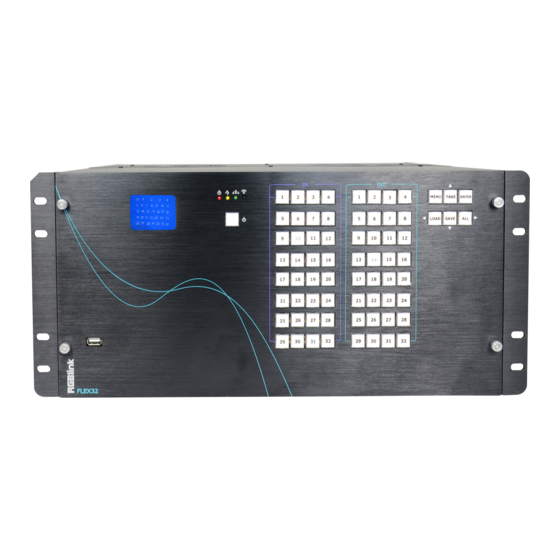
Page 9: Matrix Front Panel
Saved pages Save Button, to save current Choose all inputs or all settings to pages. outputs for matrix mode Input signal source selection Output signal selection button button under matrix mode under matrix mode User Manual FLEX 32... - Page 10 LCD display User Manual FLEX 32...
-
Page 11: Back Panel
Supports input signals including HDMI, DVI, SDI, USB and HDBaseT. Output Interface Output Card Slots Supports output signals including HDMI, DVI, SDI, USB, HDBaseT and DP. Control Interface Communication Ports RS232&LAN Connect to XPOSE software Power Connection Power Socket-IEC User Manual FLEX 32... -
Page 12: Dimension
1.2.4 Dimension Following is the dimension of FLEX 32for your reference: User Manual FLEX 32... -
Page 13: Chapter 2 Install Your Product
Connect USB-B port on the device to USB-A port on the computer by a USB A-B cable. 3. Connect to Power Connect IEC cable to device and plug into wall socket. Turn on power at wall socket. The power indicator on front panel lights. User Manual FLEX 32... -
Page 14: Chapter 3 Use Your Product
Shows : the status of each input to output and the LCD screen shows the exact info, as following example In→Out, 1→1 2→2 3→3 4→4 And the software version, serial number and IP address of the device. FLEX 32 User Manual... - Page 15 The LCD shows info as follow: FRONT PANEL LOCKED PRESS MENU 3S UNLOCK After front panel is unlocked, MENU button light goes out. WORK TIME Show the total boot times and working time up to now. BOOT TIMES: TOTAL TIME:650MIN FLEX 32 User Manual...
-
Page 16: Button Operation
I : 6 6 6 6 6 6 6 6 Press button ALL again, all lights go out except button 1 in OUT. SAVE If the IN→OUT (matrix) setting need to be saved, press button SAVE , LCD will show FLEX 32 User Manual... - Page 17 In stand by mode, press POWER for 3S, all buttons flashes one by one immediately and LCD shows RGBLINK FLEX 32 5S later, the device goes back to work and in the status before stand by. FLEX 32 User Manual...
-
Page 18: Xpose Control Flex 32
3.2 XPOSE Control FLEX 32 Minimum Requirements XPOSE Version 1.2.7.0 Windows Operation System Windows 7/8/10 Processor 1GHz/32 bit or 64 bit processor Memory Hard Disk 16Gb Graphics 128Mb/DirectX9 Display 1280×720 Operation System Mac OS Processor 1.0GHz+ Memory 512M+ Hard Disk... -
Page 19: Install Software
, it will pop-up the Installer Language box, select the language, for example, select “English”, and click “OK” to confirm. It will pop-up the installer box, and click “Next” to install, as follows: 2. Select “Browse...” to select the XPOSE software install location and click install: FLEX 32 User Manual... - Page 20 3. User should get the rights in “Roles Management” when install the software to disk C if the system is Windows 7 or above. 4. Click “Finish” and is ready to run the XPOSE management software: FLEX 32 User Manual...
-
Page 21: Login To The Software
2. If user wants to change the language to Chinese, click the drop down arrow after “Language” and select “中文”, then click “Login” to enter the software. 3. After entering the software, the main interface shows as follows: FLEX 32 User Manual... - Page 22 XPOSE management software consists of Output Setting,Operation Mode, System Settings and Log out. In the following parts come with the detail. FLEX 32 User Manual...
-
Page 23: Search The Device
Identify the device by the SN. Check the SN of the device and see if the searched one is the device you want to control. and get the device to XPOSE. FLEX 32 User Manual... - Page 24 After Sync, enter the following interface. Close the current interface, just click the X on the right top corner and enter the main menu interface. FLEX 32 User Manual...
-
Page 25: Output Setting
3.2.5 Output Setting Click Output setting and enter the interface as below: Output setting choose output resolution here FLEX 32 User Manual... - Page 26 2560×816@60Hz and 2048×1152@60Hz (not supported on DVI and HDMI output) . Then click Setting to confirm. DE Setting Board Type: select EXT-6 (EXT4F-OS) or EXT-4 (EXT4F-OM) based on the real installation of the device. Out/In: Output setting or Input setting FLEX 32 User Manual...
-
Page 27: Operation Mode
There are 2 working modes, including the Matrix mode and Splitting Mode. Click the “Operation Mode”, and enter the interface as follows: Matrix Mode and Splitting Mode are included in operation mode, specific as follows: Matrix Mode Click the “Matrix Mode”, and enter to the interface as follows: FLEX 32 User Manual... - Page 28 In→Out 1. Choose input source from the signal source list 2. Drag the signal souce to Signal 3. Click Take 4. The display will show the input source correspondingly as the following show: FLEX 32 User Manual...
- Page 29 For FLEX 32 with matrix front panel, users can use XPOSE or front panel panel to control the device. For FLEX 32 with basic front panel, users can only use XPOSE to control. 1 IN-All Out Choose one input source from the signal source list...
- Page 30 Output Card Click each output port, users can set output resolution of each port Choose Advance, scale and crop setting can be done. FLEX 32 User Manual...
- Page 31 Click the “Splitting Mode”, and pop-up window as follow: To do quick splitting, users can choose signal from signal list and drag it to the window. Drag the border of the layer to cover all the monitors. FLEX 32 User Manual...
- Page 32 Input Setting The signal list is shown as follows: It displays the input module type, the quantity of inputs and input format. Click”... “afer the format of input for the following settings: FLEX 32 User Manual...
- Page 33 Set Input Property: Right click the input and select “Input Property”, it will enter to the interface as follows: Scale: Set the X, Y, width and height. Crop: Crop the left, top, width and height. Display Mode: Select “Live” or “Freeze”. FLEX 32 User Manual...
- Page 34 Test Pattern: Slide the Test Pattern switch to enable or disable the function. For USB input setting there is USB player setting select “USB Player”, it will enter to the USB Player interface, including movie and picture, default play the USB picture. FLEX 32 User Manual...
- Page 35 USB picture player setting: Can select play in order, random, single cycle and all cycle, and switch to pre or next, pause or play. DVI module of FLEX 32 is compatible with VGA,CVBS, YPbPr signals via adapter , therefore for other signal such as VGA input, users need to choose VGA in DVI input...
- Page 36 Reset outputs: User can reset outputs by clicking the shortcut on the right side of the interface. Swap outputs: User can swap outputs by clicking the shortcut on the right side of the interface, as shown in the figure below. FLEX 32 User Manual...
- Page 37 1, and adjust the size. Click this monitor, then press button C and don’t let go, select the monitor that will set, the size of the selected monitor will be changed to the same size of monitor 1, as shown in the figure below: FLEX 32 User Manual...
- Page 38 1. Auto Adaptive 2. Adjust the proportion of output area on the interface window automatically. 3. Up Down Left Right Arrow to move the position 4. + - to adjust the size FLEX 32 User Manual...
- Page 39 Choose Board 1-4 Color Choose: Signal Souce, Color Bar, Pure Color Set TP OK Adjust Layer: Two ways can change the size and location of the opened layer: FLEX 32 User Manual...
- Page 40 Adaptive: If scale the output area to a large area, click the adaptive shortcut “ ” on the right side of the interface, the output area will be return to the best position. Layer Property Setting FLEX 32 User Manual...
- Page 41 Set the transition time, and the adjustment range is 0~10S. Slide the black out switch to enable or disable the black function. Auto take on is the default state. If select black out and auto take on, the preview image will black or FLEX 32 User Manual...
- Page 42 The special display project or LED display application would like to require special resolution settings to meet the requirement. Select the suitable input port to customize the EDID. As shown in the figure below: Loop Click the loop shortcut “ ”, and pop-up window as follows: Timing Loop FLEX 32 User Manual...
- Page 43 “ON”, the exact time to play the bank can be set. Times Loop Slide the loop switch to enable or disable the times loop function for the bank. If select “ON”, the exact length of time to play the bank can be set. FLEX 32 User Manual...
- Page 44 (Save Script) or chose Offline Saved to save saved bank to local computer Offline Saved as follows: Offline Saved Choose offline saved, it will pop window with saved banks. Choose the bank to be save and click OK, bank will be saved to local computer. FLEX 32 User Manual...
- Page 45 Click the factory reset shortcut “ ” to reset to factory settings. Factory reset is to go back to the factory initial setting of each IN-OUT. Page Set Click the page set shortcut “ ” to load and save pages. FLEX 32 User Manual...
- Page 46 Grey page indicate this page has been used, a setting has been saved in this page. Load Page Green page indicated that there is a saved available to load. Shortcut Keys Click the shortcut “ ”, and pop-up window as follows: FLEX 32 User Manual...
- Page 47 Use shortcut key to operate fast and easily. FLEX 32 User Manual...
-
Page 48: System Settings
Click “Connect Setting”: Select ”COM Port” and “Baud Rate”, click the drop down arrow after them, and click “OK”. Setting the device connecting ways: Serial Connect, Ethernet Connect and Search by this configuration. After setting ”COM Port” and “Baud Rate”, pop-up window as follows: FLEX 32 User Manual... - Page 49 This is usually used if one computer control some devices or remote control. It takes effect after reboot the software if change IP through network. System Information Click “System Information”, and pop-up window as follows: FLEX 32 User Manual...
- Page 50 Display the device version information. Including Model Number, Serial Number, IP Address, firmware version, etc. Factory Reset Click “Factory Reset”, and pop-up window as follows: Click “OK” or “Cancel” to confirm the reset. FLEX 32 User Manual...
-
Page 51: Logout
To disable Auto Fan cotrol setting, slide OFF to ON, Set Fan Speed at 0~100 3.2.8 Logout Click “Logout” to exit the XPOSE sorftware, and pop up window as follows: Click “cancel” or “OK” to confirm User also can be click the right corner red button to exit software directly FLEX 32 User Manual... -
Page 52: Chapter 4 Ordering Codes
Chapter 4 Ordering Codes Product 710-0032-01-0 FLEX 32 Modules 4.2.1 Input 190-0001-10-2 Single USB2.0 Input/Backup Input Module 190-0001-07-2 Single 3G SDI In/Loop Module 190-0001-13-2 Single HDMI Input Module 190-0001-04-2 Single DVI Input Module 190-0002-29-0 Single HDBaseT Input Module 980-0004-01-0 Single EXT4F-IM Input Interface 4.2.2 Output... -
Page 53: Chapter 5 Support
Chapter 5 Support Contact Us FLEX 32 User Manual... -
Page 54: Chapter 6 Appendix
800×600@60 | 1024×768@60 | 1280×720@50/59.94/60 | 1280×800@60 | 1280×960@60 | 1280×1024@60 | 1400×1050@60 | 1600×1200@60 | 1920×1080@23.98/24/25/29.97/30/50/59.94/60 DVI Composite Input Module Connector Appearance Numbers of Connectors Connectors DVI-I (Compatile with VGA,CVBS,YPbPr via Adapter) Supported Standard UXGA FLEX 32 User Manual... - Page 55 .DAT | .MPG 1920×1080@ 20Mbps | .MPEG MPEG2 .MPG 1920×1080@ 20Mbps MPEG4 .AVI | .MP4 DVIX | XVID 1920×1080@ 20Mbps | .3GP | .ASF RM | RMVB .RM | .RMVB RV8 | RV9 | 1280×720@3 10Mbps FLEX 32 User Manual...
- Page 56 Full Range DP Output Module Connector Appearance Numbers of Connectors Connectors DisplayPort Supported Standard DP1.1 SMPTE 720p@50/59.94/60 | 1080i@50/59.94/60 | Supported 1080p@50/59.94/60 Resolution VESA 800x600@60 | 1024x768@60 | 1280x720@50/59.94/60 | 1280x800@60 | 1280x960@60 | 1280x1024@60 | FLEX 32 User Manual...
- Page 57 1280×768@60 | 1280×800@60 |1280×1024@60/75/85 | 1360×768@60 | 1366×768@60 |1400×900@60 |1600×1050@60 | 1600×1200@60 |1680×1050@60 | 1920×1080@60 | 1920×1200@60 |2048×1152@60 | 2560 ×816@60 DVI Output Module Connector Appearance Numbers of Connectors Connectors DVI-I (Compatile with VGA,CVBS,YPbPr via Adapter) Supported Standard FLEX 32 User Manual...
- Page 58 Extras Communication LAN|UART 1×RJ45|1×RJ11 Power Supply AC 90-264V 50/60Hz 1.8A Max Max Power 400W °C-4 °C Working Environment Relativity Humidity 10% –85 % RH Weight 17kg Dimensions 484mm×458mm×221mm Product Warranty 3 years parts and labor warranty FLEX 32 User Manual...
-
Page 59: Terms & Definitions
● PAL: Phase Alternate Line. A television standard in which the phase of the colour carrier is alternated from line to line. It takes four full images (8 fields) for the colour-to-horizontalimages (8 fields) for the colour-to-horizontal phase relationship to return to the reference point. This FLEX 32 User Manual... - Page 60 TCP (UDP) Ethernet based networks. NDI is commonly found in broadcast applications. ● RTMP: Real-Time Messaging Protocol (RTMP) was initially a proprietary protocol developed by Macromedia (now Adobe) for streaming audio, video and data over the Internet, between a Flash FLEX 32 User Manual...
- Page 61 OSC protocol allows sharing data. OSC is transported via UDP packets between devices connected on an Ethernet. ● Brightness: Usually refers to the amount or intensity of video light produced on a screen without regard to colour. Sometimes called black level. FLEX 32 User Manual...
- Page 62 ● Scaling: A conversion of a video or computer graphic signal from a starting resolution to a new resolution. Scaling from one resolution to another is typically done to optimize the signal for input to an image processor, transmission path or to improve its quality when presented on a particular FLEX 32 User Manual...
- Page 63 ● EDID: Extended Display Identification Data. EDID is a data structure used to communicate video display information, including native resolution and vertical interval refresh rate requirements, to a source device. The source device will then output the provided EDID data, ensuring proper video image quality. FLEX 32 User Manual...
-
Page 64: Revision History
6.3 Revision History The table below lists the changes to the User Manual of FLEX 32. Format Time ECO# Description Personnel V1.0 2019-12-23 0000# Release Fanny FLEX 32 User Manual...
Need help?
Do you have a question about the FLEX 32 and is the answer not in the manual?
Questions and answers