
Related Manuals for NTI SPLITMUX-USBHD-4RT


Summary of Contents for NTI SPLITMUX-USBHD-4RT
- Page 1 ® SPLITMUX Series SPLITMUX-HD-4RT SPLITMUX-USBHD-4RT Quad Screen Video Splitter Installation and Operation Manual SPLITMUX-USBHD-4RT SPLITMUX-HD-4RT-R MAN225 Rev Date 9/19/16...
- Page 2 SPLITMUX Quad Screen Video Splitter TRADEMARK SPLITMUX is a registered trademark of Network Technologies Inc in the U.S. and other countries. COPYRIGHT Copyright © 2014-2016 by Network Technologies Inc. All rights reserved. No part of this publication may be reproduced, stored in a retrieval system, or transmitted, in any form or by any means, electronic, mechanical, photocopying, recording, or otherwise, without the prior written consent of Network Technologies Inc, 1275 Danner Drive, Aurora, Ohio 44202.
-
Page 3: Table Of Contents
SPLITMUX Quad Screen Video Splitter TABLE OF CONTENTS Introduction..................................1 Supported Web Browsers ............................... 2 Materials ..................................2 Connectors and LEDs ..............................3 Mounting..................................4 Single-SPLITMUX mounting............................5 Dual-SPLITMUX mounting ............................6 Reversible Mounting Assembly ..........................7 Installation ..................................8 Terminal Connection for RS232 .......................... - Page 4 SPLITMUX Quad Screen Video Splitter RS232 Command Protocol ............................. 38 Telnet Control ................................39 Using The Text Menu ..............................41 Text Menu Navigation............................41 Current Mode................................42 System Configuration ..............................43 Network Configuration ............................... 45 User Configuration..............................47 Input Configuration ..............................49 Output Configuration..............................
- Page 5 SPLITMUX Quad Screen Video Splitter Figure 8- Assembled SPLITMUX-HD-4RT-2R........................... 7 Figure 9- Video Source/Display Connections ............................ 8 Figure 10- Video Source\Display Connections- SPLITMUX-USBHD-4RT..................9 Figure 11- RS232 Terminal Connection............................10 Figure 12- Ethernet connection................................ 10 Figure 13- Direct Connect to PC..............................11 Figure 14- Front Panel Button Functions ............................
- Page 6 SPLITMUX Quad Screen Video Splitter Figure 62- Front Panel Button OSD Functions ..........................57 Figure 63- The OSD Menu................................57 Figure 64- OSD System Configuration............................. 59 Figure 65- OSD Network Configuration ............................60 Figure 66- OSD IP Settings ................................60 Figure 67- OSD Server Settings ..............................
-
Page 7: Introduction
SPLITMUX Quad Screen Video Splitter INTRODUCTION The SPLITMUX® HD Quad Screen Multiviewer allows you to simultaneously display video from four different computers or video sources on a single monitor providing resolutions up to 1920x1200 and 2048x1080. Optional USB KVM version includes a transparent USB switch with support for USB 2.0 low, full and high speed devices from connected computers. -
Page 8: Supported Web Browsers
CAT5/5e/6 unshielded twisted-pair cable(s) terminated with RJ45 connectors wired straight thru- pin 1 to pin 1, etc. for Ethernet connection Contact your nearest NTI distributor or NTI directly for all of your cable needs at 800-RGB-TECH (800-742-8324) in US & Canada or 330-562-7070 (Worldwide) or at our website at http://www.networktechinc.com... -
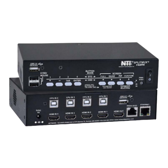
Page 9: Connectors And Leds
PCs USB Type A Female Transparent USB Hub ports for connecting USB devices (printer, flashdrive, camera, etc) to use with connected PCs (SPLITMUX-USBHD-4RT only) CPU IN 1-4 USB Type B Female For connecting USB device cables from connected PCs... -
Page 10: Mounting
SPLITMUX Quad Screen Video Splitter MOUNTING The SPLITMUX-HD-4RT can be purchased in a 1RU case with parts and hardware for mounting in a rack as a single unit (SPLITMUX-HD-4RT-R) or as a dual unit (SPLITMUX-HD-4RT-2R). Follow the instructions below for assembly and installation. Whether the SPLITMUX will be mounted as a single or a double, brackets will be attached to the case to enable mounting ears or a connector plate to be attached. -
Page 11: Single-Splitmux Mounting
SPLITMUX Quad Screen Video Splitter Single-SPLITMUX mounting 1. To mount a single SPLITMUX in a rack (SPLITMUX-HD-4RT-R), attach the rack mounting ears to the ear brackets using the #6-32 x 1/4” screws provided. Tighten all screws securely. Figure 3- Attach rack ears Figure 4- Assembled unit, ready to mount in rack 2. -
Page 12: Dual-Splitmux Mounting
SPLITMUX Quad Screen Video Splitter Dual-SPLITMUX mounting 1. To mount a dual SPLITMUX in a rack (SPLITMUX-HD-4RT-2R), attach the rack ears to the far left side of the left SPLITMUX and right side of the right SPLITMUX using the #6-32 x 1/4” screws provided. Then install a connector plate to join the two SPLITMUXs in the front. -
Page 13: Reversible Mounting Assembly
SPLITMUX Quad Screen Video Splitter Reversible Mounting Assembly If the SPLITMUXs will have the cable connections facing the front of the rack, then two more ear brackets will need to be installed to the rear corners of the cases that will be closest to each other. (Install these before attaching the connector plate to the front. -
Page 14: Installation
5. For keyboard control of the OSD menu of the SPLITMUX, connect a USB keyboard to the USB type A ports labeled “KYBD/MOUSE” on the SPLITMUX. On models supporting transparent USB device connection (SPLITMUX-USBHD-4RT), the keyboard and mouse (if connected) attached to these ports will also control the keyboard and mouse functions on any connected PC. -
Page 15: Figure 10- Video Source\Display Connections- Splitmux-Usbhd-4Rt
Figure 10- Video Source\Display Connections- SPLITMUX-USBHD-4RT 6. For SPLITMUX units supporting USB CPUs (SPLITMUX-USBHD-4RT), a USB2-AB-xM cable (where x = 0.5 meter, 3,6,10 or 15 feet)(sold separately) can be connected between a USB port on the CPU and a “CPU IN x” port corresponding with the “HDMI IN x”... -
Page 16: Terminal Connection For Rs232
SPLITMUX Quad Screen Video Splitter Terminal Connection for RS232 If control via serial connection is going to be used, serial control can be achieved by connecting a control terminal to the “RS232” port . To use the “RS232” port, connect one end of a CAT5 patch cable (supplied) to the port labeled “RS232” on the rear of the SPLITMUX. -
Page 17: Direct Connection To A Pc
SPLITMUX Quad Screen Video Splitter Direct Connection to a PC 1. Make a connection between an available RJ45 Ethernet port on a PC and the “ETHERNET” port on the SPLITMUX with a CAT5/5e/6 Ethernet cable with RJ45 male connectors on the ends, wired straight through (pin 1 to pin 1, pin 2 to pin 2, etc. Figure 13- Direct Connect to PC 2. -
Page 18: Power On
SPLITMUX Quad Screen Video Splitter POWER ON When you plug in the AC adapter between the SPLITMUX and your power supply, with the power switch OFF, the LED on the SPLITMUX will illuminate red after approximately 20 seconds. To use the SPLITMUX, press the power switch to ON. After 20 more seconds the LED will change from red (standby) to green (ON). - Page 19 SPLITMUX Quad Screen Video Splitter In QUAD screen mode, all four video sources share the screen equally. Each video source is displayed completely. In PIP mode (right) , either 2, 3 or all 4 video sources can be displayed, with the active source being displayed in its entirety on the full screen and the remaining selected images at a reduced resolution for simultaneous viewing.
-
Page 20: Osd Mode
SPLITMUX Quad Screen Video Splitter OSD Mode In OSD Mode, the buttons are used to navigate and control the SPLITMUX using the OSD menu. To bring up the OSD menu using the SPLITMUX buttons, press the FULL and QUAD buttons at the same time. To exit the OSD menu, press the FULL and QUAD buttons at the same time again. -
Page 21: Figure 15- Shake Mouse To Enter Command Mode
SPLITMUX Quad Screen Video Splitter To control the SPLITMUX using the mouse, move the mouse from side-to-side rapidly. This motion will place the SPLITMUX in Command Mode. While in Command Mode, all 3 status lights on the keyboard will illuminate to indicate that Command Mode is enabled. -
Page 22: Device Discovery Tool
DEVICE DISCOVERY TOOL In order to easily locate NTI Devices on a network, the NTI Device Discovery Tool may be used. A link to the Discovery Tool is provided on the web page that appears when you insert the instruction manual CD provided into your CD ROM drive. Either click on the link or browse the CD to locate the NTIDiscover.jar file. -
Page 23: Use And Operation Via Web Interface
IP address to enter when logging in to the SPLITMUX, or use the OSD menu to view the System Info page. Note: The computer using the Device Discovery Tool and the NTI Device must be connected to the same subnet in order for the Device Discovery Tool to work. -
Page 24: Figure 19- Initial Page- Administrator
SPLITMUX Quad Screen Video Splitter With a successful log in, a screen similar to the following will appear: Figure 19- Initial page- Administrator The initial page is the Mode page where the current operating mode of the SPLITMUX is selected and the input channel to be displayed in Full Screen mode is assigned. -
Page 25: Administration-System
SPLITMUX Quad Screen Video Splitter System Fields for applying unit settings (name and keypad PIN), Serial configuration settings, OSD screen position, and configuration backup and restore options Network Fields for providing all the network settings the SPLITMUX and access control settings Input Settings Display configuration settings for each input channel... - Page 26 SPLITMUX Quad Screen Video Splitter System Settings Description Unit Settings Name Unique name for this SPLITMUX to appear on the login page and header of each web interface page Keypad Pin PIN number that must be entered before using the keypad to change settings- 4 digits using buttons 1-4.
-
Page 27: Administration-Network
SPLITMUX Quad Screen Video Splitter Administration-Network The Network Configuration page is where all network settings are entered. These settings determine how you will remotely access the SPLITMUX. This IP address is ONLY used if the Mode is set to “Static” (settings are grayed-out when set to DHCP). -
Page 28: Administration- Input Settings
SPLITMUX Quad Screen Video Splitter Administration- Input Settings Figure 23- Input Settings Input Settings Description Input Channel x Port Name Enter a port name to associate with the video source on Input 1 Enable Choose to Enable or Disable the video input for this channel Each Input channel can be configured with these settings. -
Page 29: Administration- Output Settings
SPLITMUX Quad Screen Video Splitter Administration- Output Settings Maximum recommended level See page 21 for explanation of Audio Mode settings Indicates no audio at source Colors show input volume from source Arrows indicate output volume through SPLITMUX Figure 24- Output Settings Video Output Configuration Description Output Port Name... -
Page 30: Audio Level And Gain
SPLITMUX Quad Screen Video Splitter Video Output Resolutions to choose from (progressive scan): 640x480@60Hz 1024x768@70Hz 1280x1024@85Hz 1600x1200@85Hz 1920x1200@60Hz 640x480@75Hz 1024x768@75Hz 1400x1050@50Hz 1280x960@50Hz 1920x1080@50Hz 640x480@85Hz 1024x768@85Hz 1400x1050@60Hz 1280x960@60Hz 1920x1080@60Hz 800x600@60Hz 1280x720@50Hz 1400x1050@75Hz 1280x960@85Hz 2048x1080@60Hz 800x600@75Hz 1280x720@60Hz 1400x1050@85Hz 1280x768@60Hz 800x600@85Hz 1280x1024@50Hz 1600x1200@50Hz 1680x1050@60Hz 1024x768@50Hz 1280x1024@60Hz... -
Page 31: Administration-Mode Settings
SPLITMUX Quad Screen Video Splitter Administration-Mode Settings Figure 26- Mode Settings Power Up Mode Setting Description Power Up Mode Choose the mode the SPLITMUX will be in when powered ON Full Screen Mode Settings Description Input Channel Select the input channel assigned to Full Screen Enable Scan Enable scanning for the full screen input channel- to automatically switch from one channel to another... -
Page 32: Figure 27- Pip Screen Mode Settings
SPLITMUX Quad Screen Video Splitter Figure 27- PIP Screen Mode Settings Pip Screen Mode Settings Description Active Channel Select which active channel is in full screen mode Enable full screen Enable active input in full screen mode with overlay Enable aspect ratio Enable to maintain the aspect ratio for all displayed images PIP Mode Select how many PIP images will be displayed, 2, 3 or 4 (one will be at full screen) -
Page 33: Administration- Custom Settings
SPLITMUX Quad Screen Video Splitter Administration- Custom Settings Using the Custom Mode Settings page (Figure 28) you can customize how you want the video from each channel to appear on the display. To view custom mode settings, be sure to change the current mode setting to “Custom”... -
Page 34: Preset Layouts And Display Preview
SPLITMUX Quad Screen Video Splitter Preset Layouts and Display Preview You can use any of the 10 preset layouts (use the slide bar to scroll to 9 and 10) or you can change the presets to a custom configuration and save those as well. The window below the presets provides a preview of the spacing of each channel on the display. -
Page 35: Channel Settings
SPLITMUX Quad Screen Video Splitter Channel Settings The Aspect Ratio can be configured to be a Fixed or Free Ratio. When set to Fixed Ratio, no matter what size you drag the channel to be, the viewed image will retain the ratio of the source. When set to Free Ratio, the displayed video will adjust to whatever size or shape you have dragged that channel to be. -
Page 36: Save/Restore Layouts
SPLITMUX Quad Screen Video Splitter Save/Restore Layouts Any customized layout can be saved as a preset. Once you have the desired layout settings, click on “Download” and save the layout file to a location on your PC. Save the layout file to a location on your PC. -
Page 37: Cascade Settings
SPLITMUX Quad Screen Video Splitter Cascade Settings In order to expand the number of video inputs that can be monitored by one display, SPLITMUXs can be connected in a cascaded configuration. To cascade SPLITMUXs, simply connect the output port of any downstream SPLITMUXs to the input port of an upstream SPLITMUX. - Page 38 SPLITMUX Quad Screen Video Splitter Cascade Configuration Description Output type Direct- port will be directly connected to a display Cascade Slave- port will be connected to the Input port of an upstream SPLITMUX Output IP Address When the Output is connected to another SPLITMUX, enter the IP address of that SPLITMUX Input X (1-4) type Direct- port will be directly connected to a source Cascade Slave- port will be connected to the Output port of a downstream SPLITMUX...
-
Page 39: Administration-User Config
To edit a user’s settings, double-click on the user name within the list. The “root” username and privileges cannot be changed, but the root password can be edited. If the root password is changed and forgotten, contact NTI to provide instruction to reset the password back to “nti”. -
Page 40: Administration- Firmware
Note: In the event the SPLITMUX firmware should be corrupted, such that connection through the web interface is no longer possible, contact NTI for instruction and recovery files to access the SPLITMUX and restore the firmware using a TFTP server and Terminal connection (page 10). -
Page 41: Administration- System Information
SPLITMUX Quad Screen Video Splitter Administration- System Information The System Information page provides firmware version, serial number (version 1.1 and later), MAC address, network settings and input connection status for the SPLITMUX. This information is particularly helpful when the IP mode is set to DHCP (the default setting) because it displays the DHCP server-assigned settings, regardless of the network setting applied on the Network Configuration page (page 21) which only apply when the IP mode is set to “Static”. -
Page 42: Support
Support The Support section of the menu includes two links, Manual and Downloads. The Manual link will open the pdf manual for the SPLITMUX on the NTI website. You must have Adobe Reader installed on your PC to open this. -
Page 43: Command Line Interface
To allow multiple units to be controlled from a single host port, the RS232 control interface is designed to allow "daisy chaining" up to 15 units using an NTI Matrix-Y-1 cable. Connect the Matrix-Y-1 cable between the RJ45-to-DB9 serial adapter (provided with the RS232 option) and the CPU as shown in Figure 35. -
Page 44: Rs232 Command Protocol
SPLITMUX Quad Screen Video Splitter RS232 Matrix-Y-1 Matrix-Y-1 Matrix-Y-1 Serial Port Note: The maximum combined RS232 cable length between the RJ45 RJ45 CPU and any NTI switch cannot RJ45 TO DB9 TO DB9 exceed 50 feet. TO DB9 SERIAL SERIAL SERIAL ADAPTER... -
Page 45: Telnet Control
<SPLITMUX IP address> is IP address of the SPLITMUX (default is connect through port 2000. The user will be prompted for the root password to connect to the SPLITMUX. The factory default password is "nti". (all lowercase letters). With a proper password sent the SPLITMUX will respond with:... - Page 46 SPLITMUX Quad Screen Video Splitter The commands below are now available. Command String Good Response Description CS,IP,01 *<CR> Connect input X to the output port CM,mode,01 *<CR> Change the mode of the switch Login Prompt Open Text Menu CB 00,BR None Change baud rate of serial line, BR=11(5200),57(600),38(400),19(200)96(00),48(00),24(00),12(00)
-
Page 47: Using The Text Menu
SPLITMUX Quad Screen Video Splitter USING THE TEXT MENU The text menu can be reached either by using a serial command through the RS232 port or a Telnet command through an Ethernet connection. Either way, a text menu with full feature control can be reached by any administrative user. Text Menu Navigation •... -
Page 48: Current Mode
SPLITMUX Quad Screen Video Splitter Figure 38- Text Menu-Main Menu The Main Menu is broken into 10 categories: Function Description Current Mode Sets the current viewing mode of the SPLITMUX System Configuration Configure system settings Network Configuration Configure network settings User Configuration Configure user access settings Input Configuration... -
Page 49: System Configuration
SPLITMUX Quad Screen Video Splitter System Configuration In the System Configuration screen (Main Menu—>2) provides 3 categories of settings to configure, and provides an option to restore the SPLITMUX configuration to default settings. Figure 40- Text Menu- System Configuration The Unit Settings page provides a place to enter the name as you want it to appear in the web interface. Figure 41- Text Menu- Unit Settings... -
Page 50: Figure 42- Text Menu- Serial Port Settings
SPLITMUX Quad Screen Video Splitter Serial Settings page provides configuration of the baud rate (select a value between 1200 and 115200 bps) and the assigned serial address (1-5). Figure 42- Text Menu- Serial Port Settings The OSD Screen Settings page provides values for the placement of the OSD menu on your screen. Values of the Horizontal and Vertical Position offsets are in percentage of the screen and range from 0 to 70%. -
Page 51: Network Configuration
SPLITMUX Quad Screen Video Splitter If item 4 is selected from the System Configuration menu, you will be prompted for a “Yes” or “No” selection as to whether you are sure you want to reset all settings in the SPLITMUX to default values, or not. Be careful here, but the default answer is “No”... -
Page 52: Figure 46-Text Menu- Ipv4 Network Settings
SPLITMUX Quad Screen Video Splitter The main network settings required to connect the SPLITMUX to your network are found under IP Settings. Figure 46-Text Menu- IPv4 Network Settings (Default settings are shown in this image) IP Settings Mode Select the method for acquiring IP Settings- Static (manual), DHCP (automatic) or Disable IP Address Enter valid IPv4 address (for Static Mode) (default is 192.168.1.30) Subnet Mask... -
Page 53: User Configuration
SPLITMUX Quad Screen Video Splitter Important server settings that determine your ability to connect the SPLITMUX and stay connected are found under Server Settings. Figure 47- Text Menu-Server Settings Server Settings Enable Telnet Change to “Enable” to permit access to the SPLITMUX via Telnet The default is disabled. -
Page 54: Figure 49- Text Menu- Account Settings
SPLITMUX Quad Screen Video Splitter Figure 49- Text Menu- Account Settings Figure 50- Text Menu- User Account Settings Account Settings Username enter the name the user will use to login Password enter a password for this user to login with Confirm re-enter the password this user will login with Enabled... -
Page 55: Input Configuration
SPLITMUX Quad Screen Video Splitter Input Configuration Configure what inputs will be viewed on the display and what name they should display from the Input Configuration screen (Main Menu—>5). Select which input to configure and choose the settings to be applied. Figure 51- Text Menu- Input Configuration Input Settings Input Channel x Port Name... -
Page 56: Output Configuration
SPLITMUX Quad Screen Video Splitter Output Configuration The Output Configuration determines how the inputs will be viewed on the display (Main Menu—>6). From this menu you can also select the Audio Output Configuration which will provide settings for how the audio from the inputs is managed. Figure 52- Text Menu- Output Configuration Video Output Configuration Output Port Name... -
Page 57: Figure 53- Text Menu- Audio Output Configuration
SPLITMUX Quad Screen Video Splitter Video Output Resolutions to choose from (progressive scan): 640x480@60Hz 1024x768@75Hz 1400x1050@60Hz 1280x960@85Hz 640x480@75Hz 1024x768@85Hz 1400x1050@75Hz 1280x768@60Hz 640x480@85Hz 1280x720@50Hz 1400x1050@85Hz 1680x1050@60Hz 800x600@60Hz 1280x720@60Hz 1600x1200@50Hz 1920x1200@40Hz 800x600@75Hz 1280x1024@50Hz 1600x1200@60Hz 1920x1200@50Hz 800x600@85Hz 1280x1024@60Hz 1600x1200@75Hz 1920x1200@60Hz 1024x768@50Hz 1280x1024@75Hz 1600x1200@85Hz 1920x1080@50Hz 1024x768@60Hz 1280x1024@85Hz... -
Page 58: Mode Configuration
SPLITMUX Quad Screen Video Splitter Mode Configuration Mode Configuration (Main Menu—>7) will determine how each display mode provided by the SPLITMUX will be presented. Mode characteristics will determine how the images will look on the display. Figure 54- Text Menu- Mode Settings Menu Figure 55- Text Menu- Default Mode Configuration Power Up Mode Setting Default Power On Mode... -
Page 59: Figure 56- Text Menu- Full Screen Mode Settings
SPLITMUX Quad Screen Video Splitter Figure 56- Text Menu- Full Screen Mode Settings Full Screen Mode Settings Input Channel Select the input channel assigned to Full Screen Enable Scan Enable scanning for the full screen input channel- to automatically switch from one channel to another Scan time Set the dwell time while scanning- the amount of time (in seconds) each channel will appear... -
Page 60: Figure 58- Text Menu- Pip Mode Settings
SPLITMUX Quad Screen Video Splitter Figure 58- Text Menu- PIP Mode Settings Pip Screen Mode Settings Active Channel Select which active channel is in full screen mode Enable full screen Enable active input in full screen mode with overlay Enable aspect ratio enable the aspect ratio to be maintained for all displayed images PIP Mode Select how many PIP images will be displayed, 2, 3 or 4 (one will be at full screen) -
Page 61: Load/Save Layout
SPLITMUX Quad Screen Video Splitter Figure 59- Text Menu- Custom Mode Settings Custom Screen Mode Settings Input x (1-4) Enable Input Enter a checkmark to enable the display of the input Border color for Input Choose the color of the border around each input Border width for Input Choose the width of the border around each input- from 0-50 pixels (0 = no border) Load/Save Layout... -
Page 62: System Information
SPLITMUX Quad Screen Video Splitter Either save your current layout to one of 10 possible saved layouts…… …… or load one of up to 10 previously viewed and saved layouts. System Information Select System Information from the main menu (Main Menu—>9) to view the port status, network configuration, firmware version and MAC address for the SPLITMUX. -
Page 63: Using Osd
SPLITMUX Quad Screen Video Splitter USING OSD In OSD Mode, the front panel buttons are used to navigate and control the SPLITMUX using an on screen display (OSD) menu. To bring up the OSD menu, press the FULL and QUAD buttons at the same time. To exit the OSD menu, press them again. The OSD Mode can also be controlled using the attached keyboard and/or the mouse (if connected) from Command Mode. -
Page 64: Navigating Osd Menus Via Keyboard
SPLITMUX Quad Screen Video Splitter Navigating OSD menus via Keyboard To enter Command Mode and control the SPLITMUX OSD menu using the keyboard, press <Ctrl> + <`> (accent/tilde key) on the keyboard (press at the same time). Press <Esc> to exit Command Mode. Keypress Function O (Letter “O”) -
Page 65: System Configuration
SPLITMUX Quad Screen Video Splitter System Configuration In the System Configuration screen provides 3 categories of settings to configure. Access to the OSD menus is controlled under Unit Settings, serial communication baud rate and address under Serial Settings, and the position of the OSD menu on the display under OSD Settings. -
Page 66: Network Configuration
SPLITMUX Quad Screen Video Splitter Network Configuration The Network Configuration screen is where all network settings are entered. These settings determine how you will remotely access the SPLITMUX. Choose between your basic network (IPv4) settings and several miscellaneous server settings. Figure 65- OSD Network Configuration The IP address shown here is only used when the IPv4... -
Page 67: Figure 67- Osd Server Settings
SPLITMUX Quad Screen Video Splitter Figure 67- OSD Server Settings Server Settings Enable Telnet Change to “Enable” to permit access to the SPLITMUX via Telnet The default is disabled. Enable HTTP Change to “Enable” to allow access to the SPLITMUX via standard (non-secure) HTTP requests The default is disabled. -
Page 68: Input Configuration
SPLITMUX Quad Screen Video Splitter Input Configuration Configure what inputs will be viewed and heard on the display and what name they should display from the Input Configuration screen. Select which input to configure and choose the settings to be applied. Figure 68- OSD Input Configuration Figure 69- OSD Input Settings Input Settings... -
Page 69: Output Configuration
SPLITMUX Quad Screen Video Splitter Output Configuration The Output Configuration determines how the inputs will be viewed on the display. From this menu you can also select the Audio Output Configuration which will provide settings for how the audio from the inputs is managed. Figure 70- OSD Output Settings Video Output Settings Output Port Name... -
Page 70: Mode Configuration
SPLITMUX Quad Screen Video Splitter When Audio Mode is automatic, the audio will only be heard from that input if that input is the currently selected input. To avoid confusion from multiple audio inputs when using Quad or PIP modes, set each audio input to automatic. Video Output Resolutions to choose from (progressive scan): 640x480@60Hz 1024x768@75Hz... -
Page 71: Figure 72- Default, Full Screen And Quad Screen Settings
SPLITMUX Quad Screen Video Splitter Figure 72- Default, Full Screen and Quad Screen Settings Power Up Mode Setting Power Up Mode Choose the default mode the SPLITMUX will be in when powered ON. Choose from Full screen , PiP screen, Quad screen or Custom screen Full Screen Mode Settings Input Channel Select the input channel assigned to Full Screen... -
Page 72: Figure 73- Pip Screen Mode Settings
SPLITMUX Quad Screen Video Splitter Figure 73- PIP Screen Mode settings Pip Screen Mode Settings Active Channel Select which active channel is in full screen mode Enable full screen Enable/disable active input in full screen mode with overlay Enable aspect ratio Enable/disable the aspect ratio to be maintained for all displayed images PIP Mode Select how many PIP images will be displayed, 2, 3 or 4 (one will be at full screen) -
Page 73: Load / Save Layout
SPLITMUX Quad Screen Video Splitter Figure 74- OSD- Custom Screen Mode Settings Custom Screen Mode Settings Input x (1-4) Enable Input Enable/disable displaying the content of the input Border color for Input Choose the color of the border around the input Border width for Input Choose the width of the border around the input (0-50 pixels) (0 = no border) Load / Save Layout... -
Page 74: System Information
SPLITMUX Quad Screen Video Splitter Figure 75- Save or Load a Custom Layout Up to 10 custom layouts can be saved and re-loaded as needed. System Information Select System Information from the main menu to view the current network settings, MAC address, and port status. This is particularly helpful when the SPLITMUX is in DHCP... -
Page 75: Infrared Remote Control
SPLITMUX Quad Screen Video Splitter INFRARED REMOTE CONTROL The IRT-UNV Infrared Remote Control allows the user to remotely control up to 15 NTI SPLITMUX-HD-4RT switches, providing the ability to control connections. Materials Materials supplied with the IRT-UNV • NTI IRT-UNV Infrared Remote Control •... -
Page 76: Save And Recall
Or, the user may want to control multiple switches with a single remote, instead of having one remote per switch. To accommodate this situation, the IRT-UNV IR Remote provides the “SYS” button, which can be used to select the NTI switch to be controlled. -
Page 77: Example Of Cascaded Configuration
SPLITMUX Quad Screen Video Splitter EXAMPLE OF CASCADED CONFIGURATION In the example below, 4 SPLITMUXs are connected in a cascaded configuration. 192.168.3.183 192.168.3.145 192.168.3.125 192.168.3.173 Figure 77- View of cascaded configuration from Master The Custom Mode Settings page provides a view of the combined custom mode settings of the configuration. -
Page 78: Figure 78- View Of Cascaded Configuration From Slave At Ip 192.168.3.173
SPLITMUX Quad Screen Video Splitter tabs showing hierarchy of configuration Figure 78- View of cascaded configuration from Slave at IP 192.168.3.173 When looking at a slave unit, the hierarchy will be indicated at the upper left of the layout choices. The leftmost tab is the master, followed by the nearest connected slave. -
Page 79: Figure 80- View Of Custom Configuration Of Slave At Ip 192.168.3.183
SPLITMUX Quad Screen Video Splitter In Figure 74, it is indicated that one level of SPLITMUX is connected through channel 2 (Input 2). This is IP 192.168.3.183. Notice that in Cascade Settings the slave (192.168.3.183) is configured for connection to Input 2, and the upstream slave (192.168.3.173) is connected to the output. -
Page 80: Specifications
1- 2.1mm x 5.5mm power jack 2- USB Keyboard/Mouse (Windows or Mac) Additional Ports 2- USB 2.0 Low, Full and High Speed Transparent (SPLITMUX-USBHD-4RT only) Protocols supported HTTP, HTTPS, TCP/IP, DHCP, UDP, ARP, IPV4 Operating temperature 32 to 122°F (0 to 50°C). -
Page 81: Troubleshooting
SPLITMUX Quad Screen Video Splitter TROUBLESHOOTING Each and every piece of every product produced by Network Technologies Inc is 100% tested to exacting specifications. We make every effort to insure trouble-free installation and operation of our products. If problems are experienced while installing this product, please look over the troubleshooting chart below to see if perhaps we can answer any questions that arise.
Need help?
Do you have a question about the SPLITMUX-USBHD-4RT and is the answer not in the manual?
Questions and answers