Table of Contents
Advertisement
Quick Links
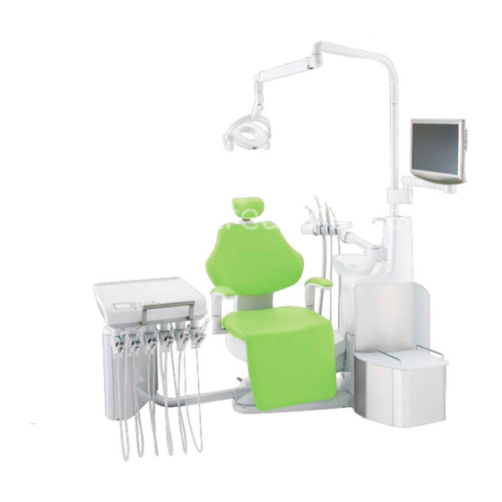
DENTAL UNIT AND CHAIR
CP-ONE PLUS
OPERATING INSTRUCTIONS
IMPORTANT
Thoroughly read this Instruction Manual before use, and use the CP-ONE PLUS according to the
instructions.
Keep this Instruction Manual carefully, and read it again whenever it is needed.
This product is a dental unit used for dental care.
People other than dentists and other dental professionals should not use this product.
Advertisement
Table of Contents

Subscribe to Our Youtube Channel
Related Manuals for Belmont CP-ONE PLUS


Summary of Contents for Belmont CP-ONE PLUS
- Page 1 CP-ONE PLUS OPERATING INSTRUCTIONS IMPORTANT Thoroughly read this Instruction Manual before use, and use the CP-ONE PLUS according to the instructions. Keep this Instruction Manual carefully, and read it again whenever it is needed. This product is a dental unit used for dental care.
-
Page 2: Table Of Contents
Table of Contents General SAFETY PRECAUTIONS ......................... 1 OPERATIONAL PRECAUTIONS FOR USE OF MEDICAL ELECTRICAL EQUIPMENT (SAFETY AND ACCIDENT PREVENTION) ................6 Chair part SAFETY PRECAUTIONS ......................... 7 OVERVIEW AND MAJOR COMPONENTS ................. 8 OPERATING INSTRUCTIONS (Optional) .................. 10 Unit part SAFETY SWITCH ........................... - Page 3 CP-ONE PLUS compliance with the following directives, MedicalDeviceDirective93/42/EEC, RoHSDirective2011/65/EU. ? Important Notes In case of the troubles, please contact Takara Belmont offices or your dealers. Do not disassemble or attempt to repair. Disassembly, repair or modifications should only be done by a qualified repair technician.
- Page 4 SYMBOLS In this book, on the labels or on the control panel of CP-ONE PLUS, following symbols are used. Confirm the meaning of each symbol. Symbol Description Symbol Description Symbol Description Symbol Description Chair Manual Chair presetting | ○ Power ON...
-
Page 5: General
General SAFETY PRECAUTIONS Before use, read the “Safety precautions” carefully to ensure proper use. The following information is designed to ensure safe use of this product and to prevent injury and damage to you and others. The precautions contained here are classified depending on the severity and degree of imminence of possible injury or damage resulting from improper use. - Page 6 General SAFETY PRECAUTIONS WARNING 9. Be sure to use the mirror cover Be sure to use the mirror cover of the dental light when the light is turned on. Direct contact with lamps may cause burns. See the Instruction Manual of the dental light for further information. 10.
- Page 7 General SAFETY PRECAUTIONS CAUTION 6. Be sure to operate switches with your hands Be sure to operate switches with your hands, except the foot controller, which is operated with your foot. Operation with body parts other than hands may cause damage or incorrect operation. 7.
- Page 8 General SAFETY PRECAUTIONS CAUTION 20. Do not use the water cleaning filter in a setting where freezing is expected Do not use the water cleaning filter in a setting where freezing is expected. Damage to parts may lead to water leakage. 21.
- Page 9 General SAFETY PRECAUTIONS NOTICE 1. Troubleshooting and contact information In the case of any problems, discontinue use, turn off the main switch and contact the dealer or our company. 2. Check operation of the compressor With no air supplied, this product does not operate even after turning on the main switch. Turn on the power of the compressor before operating this product.
-
Page 10: Operational Precautions For Use Of Medical Electrical Equipment (Safety And Accident Prevention
General OPERATIONAL PRECAUTIONS FOR USE OF MEDICAL ELECTRICAL EQUIPMENT(SAFETY AND ACCIDENT PREVENTION) 1. Only experienced personnel should use this product. 2. The following items must be taken into consideration when installing equipment. (1) Install in a location away from water or accidental splashing. (2) Install in a location which will not be adversely affected by atmospheric pressure, temperature, humidity, ventilation, sunlight, dust, air containing salt, sulfur and other substances. -
Page 11: Chair Part
Chair part SAFETY PRECAUTIONS Caution Points during Operation of the Product Description of Symbol Marks Caution areas (Moving parts should be the attention) Description of attention areas ① Take care not to be trapped by moving parts ④ Take care not to be trapped by the lower part of the headrest. -
Page 12: Overview And Major Components
Chair part OVERVIEW AND MAJOR COMPONENTS Seat Legrest Roll up Legrest... - Page 13 Chair part OPERATING INSTRUCTIONS Operation of headrest Operating instruction for Stick switch of headrest Headrest Keep depressing the headrest stick switch upward until the headrest is lifted up to the desired position. Keep depressing the headrest stick switch downward until the headrest is lowered to the desired position.
-
Page 14: Operating Instructions (Optional)
Chair part OPERATING INSTRUCTIONS (Optional) Manual operation of chair Operating instruction for Stick switch of chair manual operation Keep depressing the stick switch upward until the seat is lifted up to the desired position. Keep depressing the stick switch downward until the headrest is lowered to the desired position. - Page 15 Chair part OPERATING INSTRUCTIONS (Optional) Chair auto operation (Preset switch operation) Momentarily depress the auto mode stick switch to left side, the chair will move to the preset-1 position automatically. Momentarily depress the auto mode stick switch to right side, the chair will move to the preset-2 position automatically.
- Page 16 Chair part OPERATING INSTRUCTIONS Cancellation method of auto operation (emergency stop) During automatic movement of chair, by depress of any operating switches of chair or foot controller, the automatic movement will be cancelled and stopped immediately. Armrest ...
-
Page 17: Safety Switch
Chair part SAFETY SWITCH Safety switch (Emergency stop) All chair movements can be stopped automatically by the safety switch function when there are any articles under roll up legrest. In that case, only seat lifting and backrest rising can be operated. *Please recovery it after removing any causative articles for emergency stop. -
Page 18: Auto Operating Switch Adjustment
Chair part AUTO OPERATING SWITCH ADJUSTMENT Examining position adjustment Stick switch of chair auto operation Stick switch of chair manual operation Operating panel switch (membrane switch) of doctor table Chair last positioning switch Chair auto return switch Chair preset switch Chair manual switch In case the stick switch of chair auto operation (optional) is included. - Page 19 Chair part AUTO OPERATING SWITCH ADJUSTMENT Preset position adjustment In case the stick switch of chair auto operation (optional) is included. 1. Operate by the stick switch of chair manual operation to set up chair height and reclining angle of backrest. 2.
- Page 20 Chair part AUTO OPERATING SWITCH ADJUSTMENT Legrest position free-adjustment The legrest position upon in normal auto operation is determined up to the backrest position described as the bottom of this page. The legrest position can be adjusted by the following operation. 1.
-
Page 21: Positioning Relation Of Chair
Chair part POSITIONING RELATION OF CHAIR Legrest non-storage adjustment during LP operation The legrest angle during LP operation is as the following figure ① In case the legrest position is before LP operation, it will be lowered to ② The position directly comes to a stop in case of... -
Page 22: Safety Precautions
Unit part SAFETY PRECAUTIONS Schematic view of points requiring attention during operation of this product (illustrated with a base mount type) Description of signs Points requiring attention (parts requiring attention, including moving parts, rotary parts or detachable parts) Points requiring attention which have an emergency shutdown mechanism Base mount type Cart type Description of the numbers assigned to points requiring attention... -
Page 23: Practice Of Flush Out
Unit part PRACTICE OF FLUSH OUT Precautions for water quality safety CAUTION Practice the flush out of water retained in the unit at the beginning of each work day to maintain the quality of dental treatment water, avoid clogging of pipe and valve and ensure a steady supply of water to handpieces. -
Page 24: Overview And Major Components
Unit part OVERVIEW AND MAJOR COMPONENTS Base mount type Cart type... - Page 25 Unit part OVERVIEW AND MAJOR COMPONENTS...
-
Page 26: Operating Instructions
Unit part OPERATING INSTRUCTIONS Utility box Major master valves for opening and closing of water and air supply Junction cover Water main valve Drain valve Air master valve (inside the junction cover) ▪ The valve can be closed by turning it clockwise and opened by turning it counter-clockwise. ▪... - Page 27 Indicator the Doctor's operation panel starts to allow operation of the unit. ▪ After turning on the main switch, Belmont appears on the display of the Doctor's operation panel. Error checking starts. If there are no errors, the execution screen of flush out will appear. See page 54-55 for the procedure.
- Page 28 ○ Home screen (error conditions) ▪ If another handpiece is picked up before the first Belmont handpiece is returned to the holder, both handpieces will be inoperable even after the first handpiece is returned to the holder. In this case, the home screen will appear on the indicator, which indicates an error condition.
- Page 29 Unit part OPERATING INSTRUCTIONS Doctor's unit Description of the operation panel (membrane switches) ▪ An overview of the display and switches on the operation panel is presented in the following figure. ▪ See pages 26-31 for further information on the operation procedure. ▪...
- Page 30 Unit part OPERATING INSTRUCTIONS Doctor's unit Chair/headrest manual switches ▪ These switches provide manual operation for elevating/lowering and reclining/raising of the chair/headrest. Pressing will allow the change-over between the chair and the headrest. When the headrest is selected, the LEDs located around these switches light up.
- Page 31 Unit part OPERATING INSTRUCTIONS Doctor's unit (indicator) Bowl rinse switch ▪ Pressing this switch causes water to come from the bowl rinse nozzle for flushing the spittoon bowl. ▪ Flushing is timer-controlled. The timer has been set for approximately six seconds. ▪...
- Page 32 Unit part OPERATING INSTRUCTIONS Doctor's unit (indicator) Lock switch ▪ Pressing this switch will lock the switches on the operation panel and the stick switch of the chair. ▪ Another press of this switch will release the lock. ▪ Please use the chair lock when you clean the operation panel or when you leave the chair.
- Page 33 Unit part OPERATING INSTRUCTIONS Doctor's unit (indicator) Function switch ▪ This is the switch to set several operation states. The following operation states can be set. 1. Selection and operation of flush out 2. Setting of cupfiller 3. On/Off setting for interlocking operation between the cupfiller and the bowl rinse 4.
- Page 34 Unit part OPERATING INSTRUCTIONS Doctor's unit (indicator) Headrest auto return ▪ This is presented at the time the chair is in the zero position. Pressing with this symbol indicated will house the headrest and this symbol will disappear following completion of the movement.
- Page 35 Unit part OPERATING INSTRUCTIONS Doctor’s unit Spray on/off switch ▪ This is the switch for turning on and off handpiece cooling spray. When the handpiece is picked up and this switch is pressed, the LED on the A side (air) or W side (water) goes on, indicating the selected function.
- Page 36 Unit part OPERATING INSTRUCTIONS Doctor’s unit Instrument holder ▪ Two types of instrument holders are available: Place type Holder type Top cover Top cover Holder type and place type. ▪ The holder type and place type have the same insert ports at the top, which may be detached and replaced with each other.
- Page 37 Unit part OPERATING INSTRUCTIONS Doctor’s unit Table elevating/lowering ▪ When the table is moved up, it is fixed at that position. ▪ When moving the table down, move it up to the highest position and then move it down. WARNING Do not place objects weighing more than 3 kg on the table.
- Page 38 Unit part OPERATING INSTRUCTIONS Doctor’s unit 3-way syringe CAUTION Be careful not to drop the 3-way syringe. (Otherwise, it may break or the nozzle may deform.) 77 type 3-way syringe ▪ Water comes out when the button marked “W” is pressed.
- Page 39 Unit part OPERATING INSTRUCTIONS Doctor’s unit Operation and display of micromotor (i) Explanation and operation of micromotor rotation modes ▪ When the main switch is turned on and the micromotor is removed from the holder, the rotation mode is displayed on the indicator. ▪...
- Page 40 Unit part OPERATING INSTRUCTIONS Doctor’s unit (iii) Setting limit rotational speed DA-290N ▪ When the page feed button is pressed on the water feeding quantity adjustment screen, the screen changes to the page for setting the limit rotational speed. ▪ Increase and decrease the limit rotational speed with Limit rotational speed (min...
- Page 41 Unit part OPERATING INSTRUCTIONS Doctor’s unit Limit rotational speed ( ⅳ ) Exclusive functions and operations of NLX (min PLUS only ▪ The NLX PLUS micromotor has exclusive N-PLUS functions for setting the torque at the low revolution range (100 to 5000 min activating/deactivating the automatic reversing and automatic forward.
- Page 42 Unit part OPERATING INSTRUCTIONS Doctor’s unit ( ⅰ ) Exclusive functions and operations of BIEN Limit rotational speed MX/MX2 only (min The BIEN MX/MX2 micromotor has exclusive functions for setting the torque at the low revolution range (100 to 5000 min ), extending time to automatic forward and brightness adjustment of handpiece.
- Page 43 Unit part OPERATING INSTRUCTIONS Doctor’s unit Operation and display of the turbine ▪ When the turbine is picked up, the selected rotation mode is displayed. Four rotation modes are available: LL, LOW, (4-mode operation) STD and HI. The degree of output changes when the foot controller is stepped on.
- Page 44 Unit part OPERATING INSTRUCTIONS Doctor’s unit Operation and display of the electric scaler Setting mode ▪ When the scaler is removed from the holder, the selected mode of PERIO, ENDO and SCALING is displayed on the indicator. Use on the operation panel to select and change the mode.
- Page 45 Unit part OPERATING INSTRUCTIONS Foot controller Sensor type foot controller Pedal ▪ The rotational speed of the turbine and output of the air scaler may be adjusted by the degree of stepping on the pedal. Coolant switch ▪ The rotational speed of the motor may be Turn clockwise to decrease.
- Page 46 Unit part OPERATING INSTRUCTIONS Cuspidor unit Operation and functions of control panel 1. Water heater switch (Optional) ▪ This switch turns on and off the heater of the cupfiller water heating unit. Cup feed water becomes hot water when the switch is turned on. NOTICE When water in the heating unit becomes hot, water may drip from the cupfiller nozzle.
- Page 47 Unit part OPERATING INSTRUCTIONS Cuspidor unit USB (Optional) CAUTION The total length of cables to be connected to the USB connector should be 1 m or less. The use of improper cables may cause incorrect operation. CAUTION The USB connections within unit of doctor table side is using 4.5 m cable, as same as 2.5 m cable for the assistant side.
- Page 48 Unit part OPERATING INSTRUCTIONS Cuspidor unit Vacuum handpiece ▪ Suction starts when the vacuum handpiece is removed from the holder. ▪ In a central vacuum type system, the delay Chip (optional) circuits prevents suction from stopping immediately but continues it for approximately 4 Open seconds after returning to the holder.
- Page 49 Unit part OPERATING INSTRUCTIONS Cuspidor unit Assistant’s operation panel ▪ Operations and functions of the switches are the same as those on the operation panel of the Doctor’s unit. See pages 26-27 for the operation procedure. ▪ is an extra switch. The switch can select bowl rotation, legrest heater, spray changing and bell functions.
- Page 50 Unit part OPERATING INSTRUCTIONS (Optional) Cuspidor unit Assistant arm ▪ Height Adjustment Assistant Arm (Optional) Press the lock release button and raise arm to adjust the assistant holder height. Assistant’s arm Position at desired height and release the lock (Articulate button after that.
- Page 51 Unit part OPERATING INSTRUCTIONS Cuspidor unit Assistant’s arm and spittoon bowl safety switch ▪ The Assistant’s arm has a safety switch to prevent breakage due to interference with the chair and Safety switch is activated. Safety switch is released. ensure the safety of the patient.
- Page 52 Unit part OPERATING INSTRUCTIONS Cuspidor unit ▪ If bowl rinse link operation is active, water comes out of the bowl rinse nozzle to clean the spittoon bowl on the assistant’s operation panel as soon as cup water feeding starts. Press the bowl rinse switch or Doctor’s operation panel to stop spittoon bowl rinse halfway.
- Page 53 Unit part OPERATING INSTRUCTIONS Cuspidor unit Various types of LED indicators LED indicator function of Cuspidor unit (optional) The LEDs are lit in the specified color under the following conditions: ▪ Orange in upper part This indicator goes on when the safety switch is active.
- Page 54 Unit part OPERATING INSTRUCTIONS Operation and functions of the dental light 701 dental light (Type AL-720S) Intensity switch (with rubber cap) 1. Main switch and operation switch ▪ When the main switch of the dental unit is turned on, the indicator shown in the figure is lit in green or orange and the dental light power is turned on.
- Page 55 Unit part OPERATION SETTING Operation and functions of the dental light IO5000TA dental light (Type AL-820S) Intensity switch (with rubber cap) 1. Main switch and operation switch ▪ When the main switch of the dental unit is turned on, the indicator shown in the figure is lit in green or orange and the dental light power is turned on.
- Page 56 Unit part OPERATING INSTRUCTIONS Operation and functions of the dental light 900 dental light (Type AL-920) 1. Main switch and operation switch ▪ When the main switch of the dental unit is turned on, the indicator shown in the figure is lit in green and the dental light power is turned on.
-
Page 57: Operation Setting
Unit part OPERATION SETTING Automatic operation settings of chair * Refer to the manual of the Chair part. Presetting Move the chair to the intended examination position with the manual switch. Hold the preset switch approximately 5 seconds when the examination position is determined. - Page 58 Unit part OPERATION SETTING Function switch Settings and sequence of function switch Function switch ▪ Intended setting is enabled by selecting the Function switch on the indicator. The setting details and order are as shown below. (i) Selection and operation of flush out (ii) Setting of cupfiller FLUSHOUT (iii) On/Off setting for interlocking operation between...
- Page 59 Unit part OPERATION SETTING Function switch (i) Selection and operation of flush out ▪ Two cleaning methods can be selected. FLUSHOUT [Operation procedures] HP SET When cleaning water circuit of handpiece only Select Flush out from the functions. Select HP and press Remove the handpiece to be cleaned and set it on the The number of HP picked spittoon bowl, etc.
- Page 60 Unit part OPERATION SETTING Function switch (ii) Setting of cupfiller ▪ The cup water feeding quantity is set. ▪ The cup water feeding quantity has been adjusted before shipment. Change it, if needed, as shown below before use. [Setting procedures] Select CUPFILLER SET from the functions.
- Page 61 Unit part OPERATION SETTING Function switch Precautions for setting water feeding quantity ▪ Carry out setting in a condition where water comes out of the cupfiller nozzle normally. Water may not be fed as set if setting is carried out in a condition where water contains air, etc. ▪...
- Page 62 Unit part OPERATION SETTING Function switch (iv) On/Off setting of key touch tone ▪ Change ON and OFF setting of the key touch tone ONOFF generated when pressing the switch. KEY TOUCH TONE [Setting procedures] Select KEY TOUCH TONE from the functions. Select intended setting with and press to save.
- Page 63 Unit part OPERATION SETTING Micromotor forward/reverse switch Va The rotational speed of the micromotor may be varied up to the selected upper limit by sliding the DA-290N foot controller pedal horizontally. The rotational speed range differs with the micromotor types. ...
- Page 64 Unit part OPERATION SETTING Setting of the functions exclusive to NLX PLUS Setting of NLX PLUS torque, automatic reverse, and automatic forward ▪ The NLX PLUS micromotor has functions of setting the torque at the low revolution range (100 to 5000 rpm), activating/deactivating the automatic N-PLUS reversing and automatic forward.
- Page 65 Unit part OPERATION SETTING Setting of the functions exclusive to BIEN MX/MX2 ▪ The BIEN MX/MX2 micromotor has functions of setting the torque at the low revolution range (100 to BIEN MX 5000 rpm), activating/deactivating the automatic reversing and automatic forward. ▪...
- Page 66 Unit part OPERATION SETTING Function of calculating and displaying the micromotor gear ratio ▪ This setting function converts the gear ratio of the contra-angle handpiece to be mounted to the micromotor and displays values near the actual DA-290N revolutions. ▪ Four gear ratios are converted: ×5, ×1, ÷4 and ÷16. ▪...
- Page 67 Unit part OPERATION SETTING Setting of the quantity of water injected by the micromotor/turbine/scaler ▪ The water feeding quantity in each stage may be set (in the 01 to 07 range). The value D shows the initial value set before shipment. DA-290N ▪...
- Page 68 Unit part OPERATION SETTING Turbine mode setting 2-mode turbine HI/LOW turbine mode only 4-mode turbine HI/LOW, STD and LL turbine modes [Setting procedures] Pick the turbine up from the holder. Press the page feed button and select Select “TURBINE MODE” and press determine.
-
Page 69: Operation Stopping Function
Unit part OPERATION STOPPING FUNCTION Chair operation stopping function ▪ The safety mechanism for stopping chair operation is activated in the following cases. When the foot controller pedal is stepped on. When the spittoon bowl is turning toward the patient (Automatic operation and manual upward movement stop.) * In some cases, other display functions may... -
Page 70: Adjustment Of Parts
Unit part ADJUSTMENT OF PARTS Utility box Main air pressure reducing valve ▪ This knob adjusts the main pressure of air supplied to the unit. Knob ▪ Pull the knob and turn as shown in the drawing so that the main air pressure gauge reads a value between 0.45 and 0.5 MPa. - Page 71 Unit part ADJUSTMENT OF PARTS Cuspidor unit Water feed port adjustment knob (optional) ▪ This knob adjusts the water feeding quantity from the spare water feed port. ▪ The water quantity is decreased by turning the knob clockwise. It is Increase Decrease increased by turning the knob...
- Page 72 Unit part ADJUSTMENT OF PARTS Cuspidor unit Pressure adjustment of the water tank (optional) ▪ Adjust the pressure of air to be supplied to the Knob water tank. Decrease Increase ▪ Loosen the lock nut and turn the knob as shown in the drawing so that the pressure is lowered below 200 kPa.
-
Page 73: Cleaning
Unit part CLEANING Cuspidor unit Cleaning vacuum and saliva ejector lines ▪ The sucking unit comes into contact with secretions, spit and blood that contain bacteria every day. Be sure to clean and sterilize it with ORTLO PLUS made by DURR at the end of each work day. - Page 74 Unit part CLEANING Cuspidor unit Cleaning of the vacuum handpiece body CAUTION Cleaning must be done every after use to patients. Cleaning must be done within 1 hour after use. Replace with a new vacuum handpiece and saliva ejector handpiece for following cases.
- Page 75 Unit part CLEANING Cuspidor unit Cleaning of the solid collector ▪ Detach and wash the filter in the solid collector of the Cuspidor unit at the end of each work day. ▪ If sucked substances are collected, the suction Filter force of the vacuum is reduced.
- Page 76 Unit part CLEANING Cuspidor unit Cleaning of Assistant’s holder ▪ Use the cleaner FD333/FD366 manufactured by DURR. (Spray disinfectant mainly composed of disinfection ethanol and wipe it off, when general disinfectant is used.) ▪ The Assistant’s holder sleeve may be detached and sterilized in an autoclave (for 20 minutes at 121°C or 12 minutes at 132°C).
- Page 77 Unit part CLEANING Doctor’s unit Oil mist separator Tray mat Operation panel Holder on doctor side Dirt bin Waste receptacle (Optional) ▪ When waste accumulates, remove the paper cup (2) from the waste receptacle holder (1) and replace it. ▪...
- Page 78 Unit part CLEANING Doctor’s unit Holder on doctor side ▪ Use the cleaner FD333/FD366 manufactured by DURR. (Spray disinfectant mainly composed of disinfection ethanol and wipe it off, when general disinfectant is used.) ▪ The holder sleeve may be detached and sterilized in an autoclave (for 20 minutes at 121°C or 12 minutes at 132°C).
- Page 79 Unit part CLEANING Doctor’s unit 77 type 3-way syringe Disassembly Remove the nozzle from syringe by turning it in direction A. Cleaning by hand ・Wipe off the surface contamination by a cloth while rinsing the surface by running clean warm water at 40±5 degrees. Scrub the tip and joint part of nozzle by a cleaning brush or by a tooth brush with running clean warm water at 40±5 degrees.
- Page 80 Unit part CLEANING Utility box Cleaning air filter drain valve and discharging water from air compressor ▪ This valve is used to discharge water from the air filter. Drain valve ▪ Turn the drain valve counterclockwise to discharge water collected in the air filter once a week at least. ▪...
-
Page 81: Specifications
Unit part SPECIFICATIONS ? Base mount type ? Rated power : 230 VAC, 50 /60 Hz, 4.7/4.4 A ? Fuse : 7A/250V (C urrent Rating: 200A at 250VAC) Fast-blow Size of fuse ( 6.3 x 32mm) ? Main air pressure : 0.45-0.5 MPa ? Main water pressure : 0.1-0.2 MPa... - Page 82 Unit part SPECIFICATIONS ? Cart type ? Rated power : 230 VAC, 50/60 Hz, 4.7/4.4 A ? Fuse : 7A/250V (Current Rating: 200A at 250VAC) Fast-blow Size of fuse (6.3 x 32mm) ? Main air pressure : 0.45-0.5 MPa ? Main water pressure : 0.1-0.2 MPa ? Weight : Cuspidor unit: 45 kg...
-
Page 83: Before Requesting Repair Services
Unit part BEFORE REQUESTING REPAIR SERVICES Check the following parts first before requesting repair services, if the following phenomena take place. Phenomenon Cause Countermeasure Main switch has not been turned on. Turn on the main switch. Product does not work at Power of the compressor has not been turned Turn on the power. -
Page 84: Storage/Durable Period/Holding Of Parts/Disposal/Restriction On Use
Unit part STORAGE/DURABLE PERIOD/HOLDING OF PARTS/DISPOSAL/RESTRICTION ON USE Storage method Strictly observe the following points when the product will not be used for a long period of time (following the completion of work, during the suspension of business, etc.). Main switch ▪... -
Page 85: Others
Others CARE AND MAINTENANCE Exterior Cleaning The surface of the chair’s seating area is made of synthetic leather. Apply dry wiping or wipe the surface with cloth moistened with either water or diluted neutral detergent for the care. ... -
Page 86: Maintenance And Inspection
Others MAINTENANCE AND INSPECTION Guide for daily maintenance and inspection (Maintenance and inspection by user) Management of maintenance and inspection of medical equipment should be implemented by the user (medical institution). In case the user does not implement such management, it is permitted that such management is outsourced to a qualified entity such as a medical equipment repair company. - Page 87 Others MAINTENANCE AND INSPECTION Item Frequency Inspection method Influence if inspection Maintenance required in and diagnosis not conducted case of nonconformity Care After Flush the suction line, and Faulty suction may arise Clean the suction line and Vacuum closing then clean the filter of the filter in accordance with and saliva vacuum or saliva ejector...
- Page 88 Others MAINTENANCE AND INSPECTION Guide for Periodical Check-up Some parts and components of the products are degraded or deteriorated depending on the frequency of use. Annual check-up and maintenance, as well as replacement of consumable parts, are required. The required parts (including consumable parts) are listed below. It may be different from the following list depending on the option of the unit.
-
Page 89: Emc Information
Guidance and manufacture’s declaration – electromagnetic emissions The CP-ONE PLUS is intended for use in the electromagnetic environment specified below. The customer or the user of the CP-ONE PLUS should assure that it is used in such an environment. - Page 90 To assess the electromagnetic environment due to fixed RF transmitters, an electromagnetic site survey should be considered. If the measured field strength in the location in which the CP-ONE PLUS is used exceeds the applicable RF compliance level above, the CP-ONE PLUS should be observed to verify normal operation.
-
Page 91: Compatibility Of Handpieces
Portable and mobile RF communications equipment and the CP-ONE PLUS The CP-ONE PLUS is intended for use in an electromagnetic environment in which radiated RF disturbances are controlled. The customer or the user of the CP-ONE PLUS can help prevent electromagnetic interference by... -
Page 92: Declaration Of Conformity
Device Directive: 93/42/EEC and RoHS Directive: 2011/65/EU based on category 8 of Annex I. Product : DENTAL UNIT AND CHAIR (CLASS IIa) Model : CP-ONE PLUS *”CLASS IIa” has been defined by the rule 9 of MDD Annex IX. The product has been designed and manufactured in accordance with the European standards as the listed in the Declaration of Conformity. - Page 96 NOTE 1A07NMME BOOK NO. Printed in Japan 2017.09...
Need help?
Do you have a question about the CP-ONE PLUS and is the answer not in the manual?
Questions and answers