Belmont CLESTA eIII Installation Instructions Manual
Dental unit
Hide thumbs
Also See for CLESTA eIII:
- Installation and operation instructions manual (28 pages) ,
- Instructions for use manual (67 pages)
Table of Contents
Advertisement
DENTAL UNIT
INSTALLATION INSTRUCTIONS
This manual provides installation instructions for the CLESTA eIII.
The instructions contained in this booklet should be thoroughly read and
understood before installing the chair and unit.
After the installation has been completed, keep this manual in a safe place and
refer to it for future maintenance.
H
IMPORTANT
BOOK NO. 1E03DRD0 (4E)
Printed in JAPAN 2014-07
Advertisement
Table of Contents

Related Manuals for Belmont CLESTA eIII


Summary of Contents for Belmont CLESTA eIII
- Page 1 Printed in JAPAN 2014-07 INSTALLATION INSTRUCTIONS IMPORTANT This manual provides installation instructions for the CLESTA eIII. The instructions contained in this booklet should be thoroughly read and understood before installing the chair and unit. After the installation has been completed, keep this manual in a safe place and...
-
Page 3: Table Of Contents
TABLE OF CONTENTS Page 1. Overview and Major Components ---------------------------------------------------1 2. Dimensions and Specifications 2-1. Unit Section Specifications ---------------------------------------------------------------1 2-2. Unit Section Dimensions ------------------------------------------------------------------2 3. Installation Requirements ---------------------------------------------------------------3 4. Necessary Tools -------------------------------------------------------------------------------6 5. Installation Instructions 5-1. Unit Section Unpacking -------------------------------------------------------------------6 5-2. -
Page 4: Overview And Major Components
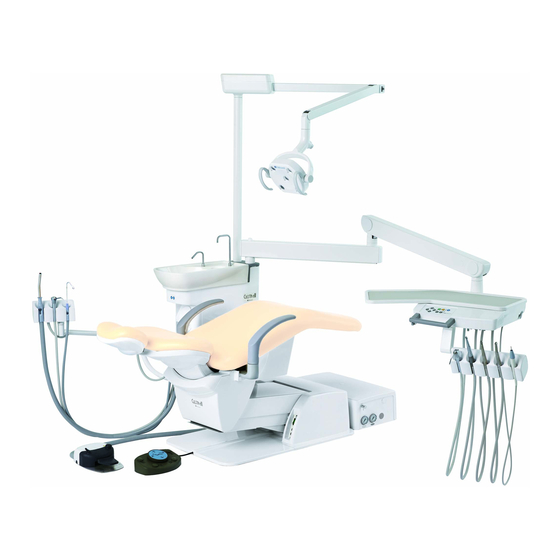
1. Overview and Major Components Light Pole Dental Light Horizontal Arm Balance Arm Cuspidor Unit Section Spittoon Bowl Assistant Control Panel Doctor Unit Section Cuspidor Control Panel Doctor Unit Section Assistant Arm Dental Viewer Assistant Holder Handpiece Holder Lock Knob Utility Box Doctor Control Panel Doctor Table... -
Page 5: Unit Section Dimensions
2-2. DIMENSIONS Over the Patient Type Cart Type (Without Light Pole) (With Light Pole) Unit : mm Dimensional tolerance: ±10% - 2 -... -
Page 6: Installation Requirements
(See page 5 for installation position and plumbing layout) (3) The area on which the CLESTA eIII is to be installed must have endurance force of 490kg/m (4) The installation position of the CLESTA eIII is shown in page 5 for installation position and plumbing layout as a recommended example. - Page 7 (1) The connection of the power supply cable is to be carried out in accordance with the local electrical regulation. (2) Capacity of the power supply (Include the CLESTA eIII Chair) 110/120V Type Single Phase 50/60 Hz : 10A 220V Type...
- Page 8 Unit : mm Dimensional tolerance: ±10% Place the Utility box Vertically Place the Utility Box Horizontally (Under the Cuspidor) (Front of the Chair Base) Base Plate Base Plate Drain (Installation reference point) min.1000 min.1000 min.800 min.800 Air Supply Vacuum Pipe Air Supply Power Source Water Supply...
-
Page 9: Necessary Tools
4. Necessary Tools for installation The following tools are necessary to assembling this product. Qty. Name of Tools 1 pc./each Phillips head screwdrivers #2~ #4 Flat head screwdriver 1 pc. 1 set Precision screwdriver set (Phillips head / Flat head) 1 pc. - Page 10 2. Open the boxes that contain parts and check the contents of each box with the accessory parts list attached to the parts box and with below list. Make sure to use provided parts such as screws, joints, and stainless flexible pipes that are used to mount the chair or for plumbing in the utility box. Also, check the necessary parts for installing the option by referring to the below list.
-
Page 11: Chair Section Preparation For Installations
5-2. Chair Section Preparation Remove the carriage bolt from the chair. * Refer to the chair installation manual for preparation of the chair. * Do not attach the backrest and seat section until the unit installation has been completed. Carriage bolt (with red tag) CAUTION Be sure to remove the carriage bolt from the chair before lift the chair by upper structure. -
Page 12: Mounting Cuspidor Unit To The Chair
-4. Mounting Cuspidor Unit to the Chair 1. Raise the dental chair to the highest position. 2. Mount the cuspidor unit on the mounting bracket of the chair and fix with four M10 x 65 flat head screw which fixed cuspidor unit to the pallet, and M10 spring washer, M10 Nut. Adjust the level of the cuspidor unit with four M10 x 30 level adjustment hex head bolt as needed. -
Page 13: Installation Of Utility Section (Plumbing)
5-5. Installation of Utility Box (Plumbing) 1. Install the water stop valve and the air stop valve to each supply pipe. The positioning of the stop valves are shown in page 5 for Installation Position and Plumbing Layout. 2. Fix the utility box to the floor with four M3.5 x 20 wood screws. M3.5 x 20 Wood Screws (4 pcs.) 3. - Page 14 4. Water and Air Supply Line Connection 1) Bend each stainless flexible pipe to a suitable angle for easily connectable between water/air stop valves and water/air filters. (See figure below) Air filter Air stop valve Be careful not to bend flexible pipe to acute angle.
-
Page 15: Electrical Connections In The Utility Section
5-6. Electrical Connections in the Utility Section * Be sure turn off the breaker of the power source line and main switch before connect the wirings. Be sure to connect the earth wire into the utility frame. 1. Connect the central vacuum operating wires to the terminal block. (This connection is central vacuum type only. -
Page 16: Installation Of The Dental Light
5-7. Installation of the Dental Light 1. Put washer (φ28.8 x φ40.5) on the light pole. Pass the light cable through the light pole and attach the dental light section to the light pole. Fix the light section and light pole with M5 x 8 set screws using the 5mm allen wrench. -
Page 17: Installation Of Accessories And Optional Parts
6. Installation of Accessories and Optional Parts * Refer to the Final Assembly File (FAF) for installing the handpiece and separator. * Do not attach the covers until the installation has been completed (Wiring, tubing connection and accessories, optional parts installation). The small size table tray and the cuspidor side panels are attached to the unit at the factory. -
Page 18: Dci Syringe
6-4. DCI Syringe - Doctor Table side - 1. Unscrew the six M4 x 12 sems screws and remove the membrane panel from the doctor table. 2. Pass the syringe tubing through to the table chassis and insert the syringe tubing to the cover hose clamp. 3. -
Page 19: Attach The Collar To The Cart Hose Guide Bracket (Cart Type)
6-5. Attach the Collar to the Cart Hose Guide Bracket (Cart type) Due to the packing, did not attach the following collar to the guide bracket at the factory. Attach the collar to the cart hose guide bracket with M4 x 35 pan head screw and cap nut using the #2 phillips head screwdriver. -
Page 20: Handpiece Flushout (Optional)
6-8. Handpiece Flushout (Optional) * Make sure to use the flushout assembling kit. Fix the flushout switch to the table chassis. Direction of the flushout switch is on direction for front side and off direction for rear side of the table chassis.(See figure) Keep the dismounted parts after replaced from kit installation for future maintenance To be... -
Page 21: Clean Water System (Dci Water Bottle)(Optional)
6-10. Clean Water System (DCI Water Bottle)(Optional) Fix the water bottle bracket on the main post with two M4 x 10 sems screws. Connect the tubings as shown on the following figure. Main post Water bottle bracket Sems screw M4 x 10 Tubings from water bottle bracket (Gray/Red/Blue) -
Page 22: Monitor Bracket (Optional)
6-12. Monitor Bracket (Optional) 1. Insert the monitor bracket bottom cover and fix the two M5 x 8 cap screws (stopper for monitor bracket) to the light pole, then insert the monitor bracket to the light pole. 2. Put washer on the monitor bracket. Pass the monitor cable through the monitor bracket and the light pole, then insert the monitor rotation shaft to the monitor bracket 3. -
Page 23: Adjustment
7. Adjustment 7-1. Water and Air Stop Valves Open the water stop valve and the air stop valve counterclockwise in the utility section. Turn on the master switch and check that water and air are not leaking. 7-2. Main Air Pressure The main air pressure has been adjusted in the factory. -
Page 24: Instrument Holder Angle Adjustment
7-5. Instrument Holder Angle Adjustment Loosen the adjustment screw located on the underside of the holder support arm. Set the holder at the client's favorite position and fix by tightening the adjustment screw using the 5mm allen wrench. Holder angle can be adjusted between 20 to 30 degrees. Instrument holder Adjustment screw 8. -
Page 25: Unit Flow Diagram
9. Unit Flow Diagram (Central Vacuum, Central Saliva Ejector, Clean Water System, Service Outlet, Flushout Switch Specifications) Balance Arm Air Brake Turbine (Optic) Air Motor Turbine (Optic) Scaler (Optic) Syringe (3 Way Syringe) Air Brake Switch Cupfiller Switch Doctor Table Section Micro Pilot Micro Pilot Micro Pilot... -
Page 26: Unit Electrical Diagram
10. Unit Electrical Diagram NEWTRON> Specifications 10-1. 100V Type (Sensor Cupfiller, Optic Turbine, Electric Scaler <SATELEC SP4055 Scaler Mode Select Switch PERIO White LED Drive Board Black SCALING Blue Black ENDO AC24V SP4055 NEWTRON Module Brown LED ON/OFF Brown Black Scaler Output White LED Output VR... -
Page 27: 200V Type
VARIOS 170> Specifications 10-2. 200V Type (Sensor Cupfiller, Optic Turbine, Electric Scaler < Scaler Mode Select Switch PERIO Yellow SCALING Black ENDO Black Green Brown White Gray Scaler Output Orange Orange Gray Control Volume White Yellow Blue Purple Black Scaler ON/OFF Purple Air Switch Black... - Page 28 TAKARA BELMONT CORPORATION 2-1-1, Higashishinsaibashi,Chuo-ku,Osaka, 542-0083,Japan TEL : +81 6 6213 5945 FAX : +81 6 6212 3680...
Need help?
Do you have a question about the CLESTA eIII and is the answer not in the manual?
Questions and answers
how to change cover on overhead light
To change the cover on a Belmont CLESTA eIII overhead light, follow these steps:
1. Use a flat head screwdriver to remove the cover fixing screws.
2. Detach the existing cover carefully.
3. Align the new cover with the mounting points.
4. Reattach it using the same cover fixing screws and secure them with the flat head screwdriver.
Make sure the power to the unit is turned off before starting.
This answer is automatically generated