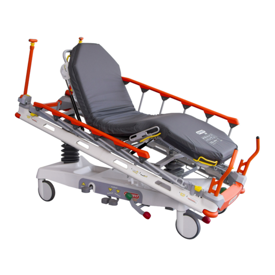
LINET Sprint 100 Service Manual
Universal transport stretcher with scales
Hide thumbs
Also See for Sprint 100:
- User manual and technical description (60 pages) ,
- Instructions for use and technical description (73 pages)

Related Manuals for LINET Sprint 100


Summary of Contents for LINET Sprint 100
- Page 1 Service Manual Sprint 100 Universal Transport Stretcher with Scales D9S001ES1-0101 Version: 04 Publication Date: 2021-04...
- Page 2 D9S001ES1-0101...
-
Page 3: Table Of Contents
Table of Contents 1 Product and Technical Label ....................... 4 2 Technical Data and Symbols ....................... 5 3 Theory of Operations ........................... 6 Undercarriage ..........................6 3.1.1 Bed lifting control (S6015663) ......................6 3.1.2 Bed lowering control (S6015713) ....................6 3.1.3 Undercarriage with hydraulic columns ................... -
Page 4: Product And Technical Label
(GS1 Data Matrix) DI + PI = UDI Symbols Serial Number PI (Product Identifier) Fig.1 Product and technical label (Sprint 100) Fig.2 Position of the Product and technical label (left upper side of the head part of the support frame) D9S001ES1-0101... -
Page 5: Technical Data And Symbols
2 Technical Data and Symbols For mechanical specifications and used symbols follow the user manual D9U001ES1-0101 for Sprint 100. D9S001ES1-0101... -
Page 6: Theory Of Operations
3 Theory of Operations Undercarriage 3.1.1 Bed lifting control (S6015663) Bed lifting depends on 2 Power Packer DSC3 PS-157 hydraulic units. The hydraulic unit is a compact element consisting of basin, pump, piston rod and valves. Lifting is reached by repeated pressing of the piston which is repeatedly returned by a spring. By stepping on the lifting pedal both piston rods are moving up simultaneously. -
Page 7: Undercarriage With Hydraulic Columns
3.1.3 Undercarriage with hydraulic columns Fig.5 Undercarriage (S6015633) 6+1 Nm Fig.6 Fixed hydraulic column - detail (S6015633) CAUTION! Material damage due to incorrect use or during service! ► Do not use pedals for lifting or lowering if the bed is not in horizontal position! In case of replacing of the column the liquid in the new column (or when the bed was placed on the side) can be mixed ►... -
Page 8: Castor Control (S6015655)
3.1.4 Castor control (S6015655) Castor levers have 3 positions. When green pedal is down one castor is arrested in bed direction. In middle position of both pedals castors are freely rotating on both axes. When red pedal is down each castor is braked. Pedals are located on bed foot end and bed head end. -
Page 9: Fifth Castor
3.1.6 Fifth Castor Technical data Value Neutral position (pedal in middle position) 12 mm - space between floor and castor Braked position (Red pedal down) 65 mm - Space between floor and castor Active position (Green pedal down) 12 mm - possible drop of the wheel below the horizontal level Maximum obstacle height 28 mm... -
Page 10: Mattress Support Platform - 4 Parts
Mattress support platform - 4 parts 3.2.1 Backrest control (S6015839, S6018773 (Wider deck)) Backrest is positioned mechanically. Two gas springs (shock absorbers) provide arresting in positions and boosting during Backrest lifting. Two separate levers in Backrest corners serve for Backrest control. From one side of Backrest or from both sides of Backrest it is possible to control both gas springs simultaneously. -
Page 11: Thighrest And Calfrest Control (S6015840, S6018800 (Wider Deck))
3.2.2 Thighrest and Calfrest control (S6015840, S6018800 (Wider deck)) Thighrest and calfrest are positioned mechanically (only for 4-part mattress support platform) . A gas spring provides arrestment in positions and boosting during Thighrest lifting. The gas spring is controlled by levers on both bed sides separately by mechanical unblocking mechanism. -
Page 12: Mattress Support Platform - 2 Parts
Mattress support platform - 2 parts 3.3.1 Backrest control (S6015839, S6018773 (Wider deck)) The backrest control and platform on 2 parts support platform is same as is on 4 parts platform. See chapter „2.2.1 Backrest control (S6015839)“ . Fig.14 Backrest with gas springs (S6015839) D9S001ES1-0101... -
Page 13: Siderails
Siderails 3.4.1 Siderail lock with the possibility of unlocking from the feet part of the bed (S6015723) Rod siderails are foldable down in direction to bed head end. Their locks are located on both bed sides at bed foot end. The lock consists of simple latch bolt which is pushed by torsion spring to shackle on the last foot rod of siderail. -
Page 14: Siderail Lock With The Possibility Of Unlocking From The Feet And The Head Part Of The Bed (S6015731, Optional)
3.4.2 Siderail lock with the possibility of unlocking from the feet and the head part of the bed (S6015731, optional) The siderail mechanism described in chapter „3.4.1 Siderail lock with the possibility of unlocking from the feet part of the bed (S6015723)“... -
Page 15: Types Of Siderails
3.4.3 Types of siderails Sprint 100 might be equipped with two types of siderails - with or without a „Soft Drop“ function. The version with the „Soft Drop“ func- tion is equipped with gas spring in the middle of siderail mechanism. Gas spring is secured with starlocks. In the siderail attachment are steel springs. -
Page 16: Scale System Lw20
Scale system LW20 Using the LW 20 system, in conjunction with tensometers, it is possible to measure the patient‘s weight and display it on the LCD display. The system can be powered by replaceable batteries or by an external AC adapter. IMPORTANT WARNING! The scale system is always configured for a specific bed. -
Page 17: Battery Module
Parameter Value Device class Transport and storage The system must be disconnected from all power supplies and batteries Scale module 315,7 x 125 x 74 mm Basic dimensions (length x width x height) Display module Battery module 156 x 125 x 74 mm Scale module 0,2kg Weight Display module 0,2kg... -
Page 18: Scale Module
The battery supply circuit is protected by a fuse tube located in the battery module. This fuse is only accessible with the tool and may only be replaced by a trained and qualified person.. Obr. 22 Battery module fuse location 3.5.2 Scale module This is the main part of the LW 20 scale system, which contains all the logic for evaluating the patient‘s weight based on data from connected tensometers. -
Page 19: Power Adapter
Battery module Scale module Scale module Battery module Battery modul Fig. 24 Location of the scale and battery module (bottom view) 3.5.3 Power adapter Provides el. energy to supply the LW 20 system from the mains. It is connected to the bed via a user-detachable connector. The adapter is equipped with interchangeable terminals for various types of el. -
Page 20: Tensometers (Weight Sensors)
3.5.4 Tensometers (weight sensors) Depending on the load, the electrical resistance in the weighing sensor changes. The change is immediately sent to the scale module, which processes the values. There are four weight sensors (tensometers) on the bed - 2 foot, 2 head. They are always fastened with eight screws (6 + 2 Nm) The sensors are connected to the terminal blocks in the weighing module.. -
Page 21: Bed Diagnostics
4 Bed diagnostics Errors – Failure States 4.1.1 „Pop-Ups“ Pop-ups appear above the main view to indicate a condition or situation that requires staff intervention. Temporary Pop-Ups hide after 5 seconds. Permanent Pop-Ups are active until their root cause disappear, eg when the error condition ends or when the BEA alarm is deactivated by the user. - Page 22 POP-UP Meaning • “Missing battery“ Pop-Up • When the user tries to turn on the BE without the battery connected, this Pop-Up window will appear. It hides 5 seconds after the last attempt to activate BE • “Loss of connection with the superior unit” Pop-Up •...
-
Page 23: Overview Of Error Codes
4.1.2 Overview of error codes Letter indicating the type of error Type of error Keyboard errors Scale system hardware errors Weighing system errors Keyboard error code Meaning (letter A) Long press (≥ 60) detected on the ZERO/T button (button No. 1) Long press (≥... - Page 24 Scale system error code Meaning (letter F) 0x40 At least one of the tensometers damaged At least one of the tensometers dangerously damaged (mechanical 0x80 damage, bed not safe) 0x100 Calibration error 0x200 No local geographic zone is set 0x400 The local altitude zone is not set 0x800 Tensometers measurement error...
-
Page 25: Visual Signaling
Visual signaling 4.2.1 Mains connection status The mains adapter is a detachable part of the LW 20. Its connection is carried out by inserting the plug of the adapter into the mains socket. The connection of the adapter to the bed is then ensured by a detachable connector located at the end of the adapter cable and its counterpart on the bed. -
Page 26: Bed Setting
5 Bed setup Service menu To access the service menu: ► Simultaneously, press BE MODE, PAUSE and PLAY/STOP buttons in that order and hold them for at least 3 seconds PLAY/STOP PAUSE BE MODE ► The main menu of the service menu opens Obr. -
Page 27: Verification Mode
5.1.1 Verification mode To access the VERIFICATION mode: ► Select VERIFICATION using the PLAY/STOP or PAUSE button ► Confirm your selection by pressing WEIGHT/CLEAR button In the VERIFICATION menu, the display shows: Position Parameter Position Parameter BSCD version Gravitational constant Calibration counter (number of performed Weight in tenth of a kg calibrations) -
Page 28: Enabling Selection Of Weighing Units (Kg / Lb)
In the DIAGNOSTICS menu, the following parameters and their values are shown on the display: Position Parameter Position Parameter Numbering T1- T4 (0 - 3) Total weight on tensometers Current status of tensometers Factory zero value Weight in grams on individual tensometers Gravitational constant value Standard deviation in grams Number of calibrations... -
Page 29: Factory Zero Setting
5.1.5 Factory zero setting WARNING! The factory zero setting is only possible if the scales are in a steady state and the bed is empty, ie without a patient and without a mattress. Before entering the FACTORY ZERO mode, make sure that the bed is unloaded, no one is touching it or that there are no shocks in the vicinity (the value on the display of the display module must be constant). -
Page 30: Gravitational Constant Setting
5.1.6 Gravitational constant setting The gravitational constant can be set separately in the G CONST menu or during the scales calibration. The menu closes after 60 seconds of inactivity (the wheel in the upper right corner), any press resets the counter. To access the CALIBRATION CONSTANT mode from the unlocked main menu (to unlock the menu, see chapter 5.1): ►... - Page 31 The gravity constant can be set according to the geographical zone of the country in the range 9761-9839 or 1 - 8. Values according to the geographical zone: Obr. 32 Gravitational constant depending on the geographical zone Zone Latitude Gravitational constant [m/s²] 0 až...
-
Page 32: Scales Calibration
5.1.7 Scales calibration WARNING! Only an authorised person may enter this mode. Each entry into the constants setup changes the calibration counter in the internal memory, and the weighing system is not regarded as a verified measuring instrument any more. The state of the calibration counter is a part of the verification label of the authorised person. - Page 33 ► The „On screen keyboard“ screen opens ► Enter the weight of the calibration weight in grams (according to the configuration 75 - 85 kg), move to the enter character and confirm the value by pressing the WEIGHT/CLEAR button NOTE: If the value is entered incorrectly, a window with the text “BAD PARAMETERS”...
- Page 34 NOTE: In case the weight is placed on a wrong position, the system detects that the most loaded tensometer is different than expected and a screen with the sign „CALIBRATION WEIGHT MISPLACED“ opens. Likewise, this error message may be displayed if the tensometers are connected incorrectly.
- Page 35 ► Place the weight on the bed above the tensometer T4 (as shown on the LCD) and press the WEIGHT/CLEAR button ► Calibration is performed ► The calibration is recorded, saved, and checked, and the CALIBRATION DONE screen is displayed ►...
- Page 36 Error message screen Error/Possible cause Solution Restart the weighing module and repeat the calibration If the error persists, the scale General calibration error module may be defective. Contact the manufacturer‘s service center. D9S001ES1-0101...
-
Page 37: Service Tools And Equipment
6 Service Tools and Equipment List of tools and equipment Socket set Tape measure Knife Hex / Torx key bit set Screwdriver set Hammer, nylon hammer Engineer‘s wrench set Torque wrench M1 20kg Calibration Weight Hex key set (4 pcs) Set of pliers D9S001ES1-0101... - Page 38 274 01 Slaný Phone: +420 312 576 111 Fax: +420 312 522 668 E-mail: info@linet.cz http://www.linet.com Service department: service@linetgroup.com Sprint 100 with scales Universal Transport Stretcher Author: LINET, s.r.o. Related links: www.linet.com D9S001ES1-0101 Version: 04 Publication Date: 2021-04 Copyright © LINET, s.r.o., 2021 Translation ©...
Need help?
Do you have a question about the Sprint 100 and is the answer not in the manual?
Questions and answers