Table of Contents
Advertisement
Quick Links
TECHNICAL MANUAL
Of
Intel Q370 Express Chipset
Based Mini-ITX M/B
NO. G03-NF797-F
Revision: 4.0
Release date: December 15, 2020
Trademark:
* Specifications and Information contained in this documentation are furnished for information use only, and are
subject to change at any time without notice, and should not be construed as a commitment by manufacturer.
Advertisement
Table of Contents

Related Manuals for JETWAY HBJC501F797-Q37-B


Summary of Contents for JETWAY HBJC501F797-Q37-B
- Page 1 TECHNICAL MANUAL Intel Q370 Express Chipset Based Mini-ITX M/B NO. G03-NF797-F Revision: 4.0 Release date: December 15, 2020 Trademark: * Specifications and Information contained in this documentation are furnished for information use only, and are subject to change at any time without notice, and should not be construed as a commitment by manufacturer.
- Page 2 Environmental Protection Announcement Do not dispose this electronic device into the trash while discarding. To minimize pollution and ensure environment protection of mother earth, please recycle.
-
Page 3: Table Of Contents
TABLE OF CONTENT ENVIRONMENTAL SAFETY INSTRUCTION................iii USER’S NOTICE..........................iv MANUAL REVISION INFORMATION...................iv ITEM CHECKLIST..........................iv CHAPTER 1 INTRODUCTION OF THE MOTHERBOARD FEATURE OF MOTHERBOARD..................1 SPECIFICATION........................2 LAYOUT DIAGRAM.......................3 CHAPTER 2 HARDWARE INSTALLATION JUMPER SETTING........................ 8 CONNECTORS AND HEADERS..................12 2-2-1 CONNECTORS......................12 2-2-2 HEADERS........................ -
Page 4: Environmental Safety Instruction
Environmental Safety Instruction Avoid the dusty, humidity and temperature extremes. Do not place the product in any area where it may become wet. 0 to 40 centigrade is the suitable temperature. (The temperature comes from the request of the chassis and thermal solution) ... -
Page 5: User's Notice
USER’S NOTICE COPYRIGHT OF THIS MANUAL BELONGS TO THE MANUFACTURER. NO PART OF THIS MANUAL, INCLUDING THE PRODUCTS AND SOFTWARE DESCRIBED IN IT MAY BE REPRODUCED, TRANSMITTED OR TRANSLATED INTO ANY LANGUAGE IN ANY FORM OR BY ANY MEANS WITHOUT WRITTEN PERMISSION OF THE MANUFACTURER. -
Page 6: Chapter 1 Introduction Of The Motherboard
Chapter 1 Introduction of the Motherboard 1-1 Feature of Motherboard Intel ® Q370 express chipset Support LGA 1151 CPU socket for the 8 Intel Coffee Lake processors (TDP ≤ ® 65W, and the whole system power consumption under 120W). ... -
Page 7: Specification
1-2 Specification Spec Description Mini-ITX form factor; PCB size:17.0x17.0cm Design Intel Q370 Express Chipset Chipset Intel ® LGA 1151 Socket for Coffee Lake series processors CPU Socket * for detailed CPU support information please visit our website ... -
Page 8: Layout Diagram
2* RJ-45 LAN port 1*3-phone audio jack (Line-in, Line-out, MIC) Internal I/O Connectors & Headers: 1 *2-pin internal 9V~36V power connector 1*SATA power-out connector 1* CPUFAN connector & 1* SYSFAN connector 2* internal vertical USB 3.1 (Gen.2) ports ... - Page 9 Motherboard Internal Diagram: Internal CPUFAN DC 9V~36V Connector Power Connector DDR4 eDP Port SODIMM Slots Header (SODIMM1/SODIMM2) LGA 1151 *Rear IO CPU Socket Connector (Refer to Page-3) M.2 M-Key Slot LAN_LED (M2M) Header SMBUS Header Intel Chipset GPIO Header 2*SATAIII Ports M.2 E-Key Slot (M2E) SATA Power-out...
- Page 10 Motherboard Jumper Positions: AT_COPEN JBAT...
- Page 11 Jumper Name Description JBAT Pin (1-2): Clear CMOS RAM Settings 6-pin Block Pin (3-4): Flash Descriptor Override Pin (5-6): PWROK Override COM1 Port Pin9 Function Select 4-pin Block LCD Backlight Select 4-pin Block LCD Panel VCC Select 4-pin Block AT_ COPEN Pin (1-2): AT Mode Select 4-pin Block Pin (3-4): Case Open Display Select...
- Page 12 Headers Name Description JW_FP Front Panel Header(PWR LED/ HD 9-pin Block LED/Power Button /Reset) PS2KBMS PS2 Keyboard & Mouse Header 6-pin Block SMBUS SMBUS Header 4-pin Block FP_USB20 USB 2.0 Port Header 9-pin Block /FP_USB21 FP_AUDIO Front Panel Audio Header 9-pin Block LAN_LED LAN Activity LED Header...
-
Page 13: Chapter 2 Hardware Installation
Chapter 2 Hardware Installation 2-1 Jumper Setting Pin 1&2 of JBAT (6-pin): Clear CMOS RAM Setting Pin 1&2 of JBAT → Clear CMOS JBAT Pin1 1-2 Open: Normal(Default); Pin1 1-2 Closed: Clear CMOS(One Touch). Pin 3&4 of JBAT (6-pin): Flash Descriptor Override Select Pin 3&4 of JBAT →... - Page 14 Pin 5&6 of JBAT (6-pin): PWROK Override Select Pin 5&6 of JBAT → PWROK Override JBAT Pin1 5-6 Open: Normal(Default); Pin1 5-6 Closed: PWROK Override. * Note : PWROK override is for manufacturing test only. JP1 (4-pin): COM1 Port Pin9 Function Select...
- Page 15 JP4 (3-pin): LCD Backlight Select JP5 (4-pin): LCD Panel VCC Select ** Note : The maximum carried current is 1A.
- Page 16 Pin 1&2 of AT_COPEN (4-pin): ATX Mode/AT Mode Select Pin 1&2 of AT_COPEN → ATX/AT Mode Select AT_COPEN Pin1 1-2 Open: ATX Mode Selected(Default); Pin1 1-2 Closed: AT Mode Selected. *ATX Mode Selected: Press power button to power on after power input ready; AT Mode Selected: Directly power on as power input ready.
-
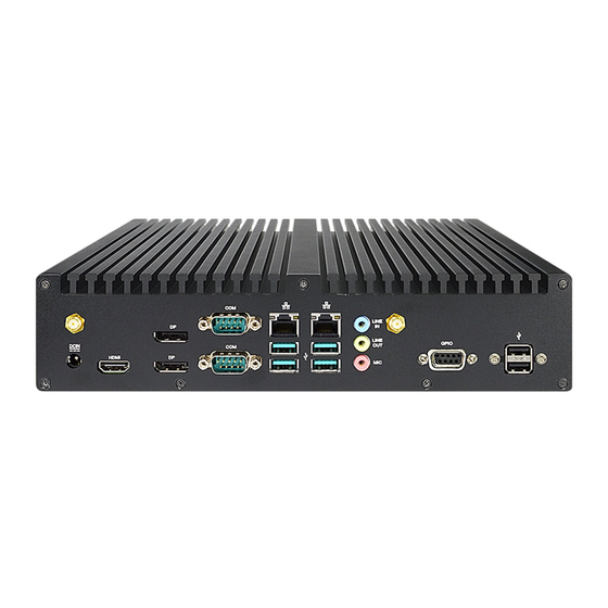
Page 17: Connectors And Headers
Connectors and Headers 2-2-1 Connectors Rear Panel Connectors *Refer to Page-3 Rear IO Diagram Icon Name Function For user to connect compatible power adapter to provide 9V~36V DC-in power supply for the system. Power Jack To connect display device that support HDMI HDMI Port specification. - Page 18 (1) COM12: RS232/422/485 Ports COM1/COM2 port can function as RS232/422/485 port. In normal settings COM1/COM2 functions as RS232 port. With compatible COM cable COM1/COM2 can function as RS422 or RS 485 port. User also needs to go to BIOS to set ‘Transmission Mode Select’...
- Page 19 (3) SATA1/2 (7-pin): SATAIII Port connector These are high-speed SATAIII port that supports 6GB/s transfer rate. SATA1 Pin No. Definition SATA2 (4) SATAPWR (4-pin): SATA HDD Power-Out Connector SATAPWR Pin1 Warning: Make sure that Pin-1 of compatible SATA Power connector is inserted into corresponding Pin-1 of SATAPWR connector to avoid possible damage to the board and hard disk drive!
- Page 20 (5) SYSFAN (4-pin): System Fan Connector SYSFAN Pin1 (6) CPUFAN(4-pin): CPU Fan Connector CPUFAN Pin1...
-
Page 21: Headers
2-2-2 Headers (1) JW_FP (9-pin): Front Panel Header JW_FP (2) PS2KBMS (6-pin): PS/2 Keyboard & Mouse Header PS2KBMS... - Page 22 (3) SMBUS (4-pin): SMBUS Header SMBUS Pin 1 SMBUS_CLK SMBUS_DATA (4) FP_USB20/FP_USB21 (9-pin): USB 2.0 Port Header FP_USB20 Pin 1 FP_USB21...
- Page 23 (5) FP_AUDIO (9-pin): Line-Out, MIC-In Header This header connects to Front Panel Line-out, MIC-In connector with cable. FP_AUDIO (6) LAN_LED (4-pin): LAN Activity LED Header LAN2LED- LAN2LED+ LAN1LED- LAN1LED+ LAN_LED Pin 1...
- Page 24 (7) EDP (40-pin): 4-lane eDP Header Pin40 Pin20 Pin21 Pin1 Pin Define Pin NO. Pin NO. Pin Define Pin 40 Pin 20 LCD_VCC BL_PWR Pin 39 Pin 19 LCD_VCC BL_PWR Pin 38 Pin 18 LCD_VCC BL_PWR Pin 37 Pin 17 BL_PWR Pin 36 Pin 16...
- Page 25 (8) GPIO (10-pin): GPIO Port Header GPIO Pin 1...
-
Page 26: Chapter 3 Introducing Bios
Chapter 3 Introducing BIOS Notice! The BIOS options in this manual are for reference only. Different configurations may lead to difference in BIOS screen and BIOS screens in manuals are usually the first BIOS version when the board is released and may be different from your purchased motherboard. Users are welcome to download the latest BIOS version form our official website. -
Page 27: Bios Menu Screen
3-2 BIOS Menu Screen The following diagram show a general BIOS menu screen: Menu Bar General Help Items Current Setting Value Menu Items Function Keys 3-3 Function Keys In the above BIOS Setup main menu of, you can see several options. We will explain these options step by step in the following pages of this chapter, but let us first see a short description of the function keys you may use here: ... -
Page 28: Getting Help
[F1]: General help. [F2]: Previous values. [F3]: Optimized defaults. [F4]: Save & Exit. Press <Esc> to exit from BIOS Setup. 3-4 Getting Help Main Menu The on-line description of the highlighted setup function is displayed at the top right corner the screen. -
Page 29: Main Menu
3-6 Main Menu Main menu screen includes some basic system information. Highlight the item and then use the <+> or <-> and numerical keyboard keys to select the value you want in each item. System Date Set the date. Please use [Tab] to switch between date elements. System Time Set the time. -
Page 30: Advanced Menu
3-7 Advanced Menu CPU Configuration Press [Enter] to view current CPU configuration and make settings for the following sub-items: Hyper-Threading The optional settings: [Disabled]; [Enabled]. When set as [Disabled] only one thread per core is enabled. [Enabled]: for Windows and Linux (OS optimized for Hyper-Threading Technology). - Page 31 Intel(R) SpeedStep(tm) This item allows more than two frequency ranges to be supported. The optional settings are: [Disabled]; [Enabled]. C states The optional settings are: [Disabled]; [Enabled]. Use this item to enable or disable CPU Power Management. When set as [Enabled], it allows CPU to go to C states when it’s not 100% utilized. Turbo Mode Use this item to enable or disable Turbo Mode.
- Page 32 ME FW Image Re-Flash Use this item to enable or disable ME FW Image Re-Flash function. The optional settings are: [Disabled]; [Enabled]. * In the case that user needs to update ME firmware, user should set ‘ME FW Image Re-Flash’ as [Enabled], save the settings and exit. The system will turn off and reboot after 4 seconds.
- Page 33 CIRA Timeout OEM defined timeout for MPS connection to be established. The setting range is from [0] to [255]. [0]: use the default timeout value of 60 seconds; [255]: MEBx waits until the connection succeeds. ASF Configuration This item is for user to configure Alert Standard Format parameters. Press [Enter] to make settings for in the following sub-items: PET Progress Use this item to enable or disable PET Events Progress to receive PET Events.
- Page 34 OEM Flags Settings Use this item to configure OEM flags. Press [Enter] to make settings for in the following sub-items: Hide Unconfigure ME Confirmation Prompt Use this function to enable or disable Hide Unconfigure ME Configuration Prompt when attempting ME unconfiguration. The optional settings are: [Disabled];...
- Page 35 The optional settings are: [Disabled]; [Enabled]. *When set as [Enabled], user can make further settings in the following items: Pending Operation Use this item to schedule an operation for the security device. Your computer will reboot during restart to change state of device. The optional settings are: [None];...
- Page 36 USB S3/S4 Wake-up The optional settings are: [Enabled]; [Disabled]. Use this item to enable or disable USB wake-up from S3/S4 state. *This function is supported when ‘ERP Support’ is set as [Disabled]. USB S5 Power Use this item to enable or disable USB power after power shutdown. *This function is supported when ‘ERP Support’...
- Page 37 WatchDog Reset Timer Use this item to enable or disable WDT reset function. *When set as [Enabled], the following sub-items shall appear: WatchDog Reset Timer Value User can set a value in the range of [4] to [255]. WatchDog Reset Timer Unit The optional settings are: [Sec.];...
- Page 38 when above this pre-set duty. CPUFAN / SYSFAN Idle-Speed Temperature Use this item to set CPUFAN/SYSFAN idle speed temperature. Fan will run at idle speed when below this pre-set temperature. CPUFAN / SYSFAN Idle-Speed Duty Use this item to set CPUFAN/SYSFAN idle speed duty. Fan will run at idle speed when below this pre-set duty.
- Page 39 Data Bits The optional settings are: [7]; [8]. Parity A parity bit can be sent with the data bits to detect some transmission errors. The optional settings are: [None]; [Even]; [Odd]; [Mark]; [Space]. [Even]: parity bit is 0 if the num of 1’s in the data bits is even; [Odd]: parity bit is 0 if num of 1’s in the data bits is odd;...
- Page 40 Legacy Console Redirection Legacy Console Redirection Settings Press [Enter] to make settings for the following item: Legacy Console Redirection Settings Redirection COM Port For user to select a COM port to display redirection of legacy OS and Legacy OPROM messages. The optional settings are: [COM1];...
- Page 41 Terminal Type The optional settings: [VT100]; [VT100+]; [VT-UTF8]; [ANSI]. [VT-UTF8] is the preferred terminal type for out-of-band management. The next best choice is [VT100+] and them [VT100]. See above, in Console Redirection Settings page, for more help with Terminal Type/Emulation. Bits per second Use this item to select serial port transmission speed.
- Page 42 XHCI Hand-off This is a workaround for OSes without XHCI hand-off support. The XHCI ownership change should be claimed by XHCI driver. The optional settings are: [Enabled]; [Disabled]. USB Mass Storage Driver Support Use this item to enable or disable USB mass storage driver support. The optional settings are: [Disabled];...
- Page 43 Ipv6 PXE Support The optional settings are: [Disabled]; [Enabled]. Use this item to enable IPv6 PXE boot support. When set as [Disabled], IPv6 boot support will not be available. PXE boot wait time Use this item to set wait time to press [ESC] key to abort the PXE boot. Use either [+] / [-] or numeric keys to set the value.
-
Page 44: Chipset Menu
Ethernet Connection (7) I219-LM- XX:XX:XX:XX:XX:XX This item shows current network brief information. 3-8 Chipset Menu System Agent (SA) Configuration Press [Enter] to make settings for the following sub-items: VT-d The optional settings are: [Enabled]; [Disabled]. ► Memory Configuration Press [Enter] to view brief information for the working memory module. ►... - Page 45 The optional settings are: [VBIOS Default]; [DP1]; [DP2]; [HDMI]; [eDP]. *Note: In the case that the ‘Primary IGFX Boot Display’ is select as [DP1], [DP2], [HDMI], or [eDP], user can make further settings in ‘Secondary IGFX Boot Display’: Secondary IGFX Boot Display Use this item to select the secondary Display device.
- Page 46 Onboard Lan1 Controller Use this item to enable or disable corresponding onboard NIC device or controller. The optional settings are: [Disabled]; [Enabled]. *When set as [Enabled], the following sub-items shall appear: Wake on LAN Enable Use this item to enable or disable integrated LAN to wake the system. The optional settings are: [Disabled];...
-
Page 47: Security Menu
3-9 Security Menu Security menu allow users to change administrator password and user password settings. Administrator Password If there is no password present on system, please press [Enter] to create new administrator password. If password is present on system, please press [Enter] to verify old password then to clear/change password. - Page 48 The optional settings are: [Disabled]; [Enabled]. Secure Boot feature is active if Secure Boot is enabled, Platform Key (PK) is enrolled and the system is in User mode. The mode change requires platform reset. Secure Boot Mode The optional settings are: [Standard]; [Custom]. Set UEFI Secure Boot Mode to Standard mode or Custom mode.
- Page 49 Enroll Efi Image This item allows the image to run in Secure Boot Mode. Enroll SHA256 Hash certificate of a PE image into Authorized Signature Database (db). Device Guard Ready Remove ‘UEFI CA’ from DB Device Guard ready system must not list ‘Microsoft EFI CA’ Certificate in Authorized Signature database (db).
-
Page 50: Boot Menu
3-10 Boot Menu Boot Configuration Setup Prompt Timeout Use this item to set number of seconds to wait for setup activation key. Bootup Numlock State Use this item to select keyboard numlock state. The optional settings are: [On]; [Off]. Quiet Boot The optional settings are: [Disabled];... -
Page 51: Save & Exit Menu
3-11 Save & Exit Menu Save Options Save Changes and Reset This item allows user to reset the system after saving the changes. Discard Changes and Reset This item allows user to reset the system without saving any changes. Default Options Restore Defaults Use this item to restore /load default values for all the setup options.
Need help?
Do you have a question about the HBJC501F797-Q37-B and is the answer not in the manual?
Questions and answers