Table of Contents
Advertisement
Quick Links
M/B For Socket 370 Pentium
Trademark:
* Pentium is registered trademark and MMX is a trademark of Intel Corporation,
the other names and brands are the property of their respective owners
* Specifications and Information contained in this documentation are furnished for information use only, and are
subject to change at any time without notice, and should not be construed as a commitment by manufacturer.
618AF/618AS
USER'S MANUAL
NO. G03-618AFR5A
Release date: November 2001
** Year 2000 compliant **
III Processor
Advertisement
Table of Contents

Related Manuals for JETWAY 618AFR5A


Summary of Contents for JETWAY 618AFR5A
- Page 1 618AF/618AS USER'S MANUAL M/B For Socket 370 Pentium III Processor NO. G03-618AFR5A Release date: November 2001 ** Year 2000 compliant ** Trademark: * Pentium is registered trademark and MMX is a trademark of Intel Corporation, the other names and brands are the property of their respective owners * Specifications and Information contained in this documentation are furnished for information use only, and are subject to change at any time without notice, and should not be construed as a commitment by manufacturer.
-
Page 2: Table Of Contents
TABLE OF CONTENT USER’S NOTICE................ii MANUAL REVISION INFORMATION..........1 THERMAL SOLUTIONS..............1 CHAPTER 1 INTRODUCTION OF MOTHERBOARD 1-1 FEATURE OF MOTHERBOARD ..........2 1-2 SPECIFICATION ..............3 1-3 PERFORMANCE LIST ............4 1-3-1 618AF................... 1-3-2 618AS ......................1-4 LAYOUT DIAGRAM & JUMPER SETTING ........ 6 CHAPTER 2 HARDWARE INSTALLATION 2-1 HARDWARE INSTALLATION STEPS ........ -
Page 3: User's Notice
3-9 PNP/PCI CONFIGURATION SETUP .......... 39 3-10 PC HEALTH STATUS............. 40 3-11 MISCELLANEOUS CONTROL ..........41 3-12 LOAD STANDARD/OPTIMIZED DEFAULTS ......42 3-13 SET SUPERVISOR/USER PASSWORD ........42 CHAPTER 4 DRIVER & FREE PROGRAM INSTALLATION MAGIC INSTALL SUPPORTS WINDOWS 95/98/98SE/NT4.0/2000 ..43 4-1 INF ....... -
Page 4: Manual Revision Information
Manual Revision Information Reversion Revision History Date Fifth Edition November 2001 Item Checklist Motherboard Cable for IDE/Floppy CD for motherboard utilities ¡ ¼ Cable for USB Port 3/4 (Option) User’s Manual Intel Processor Family Thermal Solutions As processor technology pushes to faster speeds and higher performance, thermal management becomes increasingly crucial when building computer systems. -
Page 5: Feature Of Motherboard
Chapter 1 Introduction of 618AF/618AS Motherboard 1-1 Feature of motherboard The 618AF/618AS motherboard is design for use Intel’s new generation Pentium processors, which utilize the Socket 370 design and the memory size expandable to 512MB. This motherboard use the newest Intel chipset, whose 133MHz front side bus & 133MHz memory interface delivers a clear upgrade path to the future generation of 133MHz processors and PC-133 SDRAM. -
Page 6: Specification
1-2 Specification Spec Description ∗ ATX form factor 4 layers PCB size: 30.5x18cm Design ∗ INTEL 815E Chipset for 618AF; Intel 815EP chipset for 618AS Chipset ∗ Winbond 83195BR-25 Clock Generator ∗ Support 66/100/133MHz system Bus Clock (CPU Bus Clock) ∗... -
Page 7: Performance List
1-3 Performance List 1-3-1 618AF The following performance data list is the testing result of some popular benchmark testing programs. These data are just referred by users, and there is no responsibility for different testing data values gotten by users (the different Hardware & Software configuration will result in different benchmark testing results.) ... -
Page 8: 618As
1-3-2 618AS The following performance data list is the testing result of some popular benchmark testing programs. These data are just referred by users, and there is no responsibility for different testing data values gotten by users (the different Hardware & Software configuration will result in different benchmark testing results.) ... -
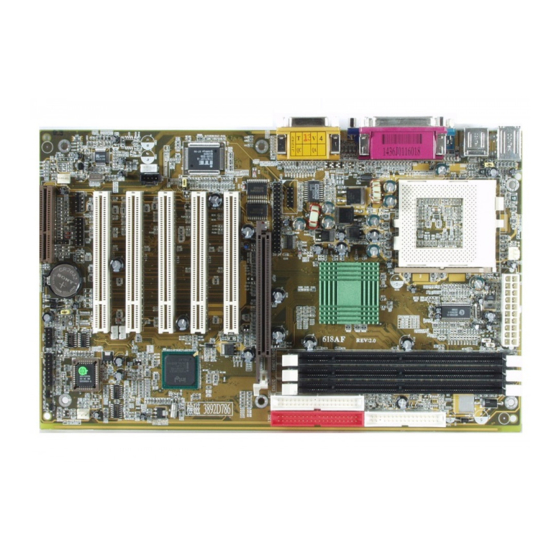
Page 9: Layout Diagram & Jumper Setting
1-4 Layout & Jumper Setting PS/2 MOUSE PRINT GAME/MIDI PORT PS/2 KEYBOARD COM1 LINE-OUT LINE-IN COM 1 PS/2 GAME MOUSE PRINT AC97 & K/B ITE 8712F JP11 LINE-IN LINE-OUT USB A CODEC FAN1 JP10 BATT. 82815 DIMM1 CN10 82801BA DIMM2 DIMM3 IDE2 IDE1... -
Page 10: Expansion Sockets
Jumpers Jumper Name Description Page JS2, JS3 CPU & SDRAM Frequency Setting 3-pin Block JS1, JS4 2-pin Block Keyboard Power ON Function Setting 3-pin Block Clear Keyboard Power On Password Setting 3-pin Block CMOS RAM Clear 3-pin Block Onboard Audio CODEC Setting 3-pin Block Connectors Connector... -
Page 11: Hardware Installation Steps
Chapter 2 Hardware installation 2-1 Hardware installation Steps Before using your computer, you had better complete the following steps: 1. Check motherboard setting 2. Install CPU 3. Install Memory 4. Install Expansion cards 5. Connect Ribbon cables, Panel wires, and power supply 6. - Page 12 Disabled Enabled Keyboard Power On Function 3. Clear Keyboard Power On password setting (3-pin) : JB2 You can set keyboard power on function password to assure computer security to setting password through BIOS SETUP, and you can clear keyboard power on password by JB2.
-
Page 13: Install Cpu
2-3 Install CPU 2-3-1 Glossary Chipset (core logic) - two or more integrated circuits which control the interfaces between the system processor, RAM, I/O devises, and adapter cards. Processor socket - the socket used to mount the system processor on the motherboard. Slot (AGP, PCI, ISA, RAM) - the slots used to mount adapter cards and system RAM. -
Page 14: Setting Cpu Bus Clock & Memory Clock Jumper
The way to recognize the specification of CPU from the packing Pentium III 370 pins FC-PGA On the surface of the CPU as shown on the right picture, under the word of “PENTIUM III” the code is: RB 80526 P2 866 256 RB : FC–PGA packing : P2–133MHz front side bus frequency PY–100MHz front side bus frequency... -
Page 15: Install Cpu
2-3-3 Install CPU This motherboard Provides a ZIF socket 370. The CPU that comes with the motherboard should have a cooling FAN attached to prevent overheating. If this is not the case, then purchase a correct cooling FAN before you turn on your system. WARNING! Be sure that there is sufficient air circulation across the processor’s heatsink and CPU cooling FAN is working correctly, otherwise it may... -
Page 16: Install Memory
CMOS Setup Utility – Copyright(C) 1984-2000 Award Software Miscellaneous Control CyrixIII Clock Ratio Default Item Help Auto Detect DIMM/PCI Clk Enabled Spread Spectrum Disabled ** Current Host Clock is 66Mhz ** Menu Level > CPU Host/SDRAM/PCI Clock 66/100/33Mhz CPU Clock Ratio CyrixIII CPU Ratio Adjust Move Enter:Select Item +/-/PU/PD:Value F10:Save ESC:Exit... -
Page 17: Expansion Cards
Generally, installing SDRAM modules to your motherboard is very easy, you can refer to figure 2-4 to see what a 168-Pin PC100 & PC133 SDRAM module looks like. DIMM1 (BANK0+BANK1) DIMM2 (BANK2+BANK3) Figure 2-4 DIMM3 (BANK4+BANK5) NOTE! When you install DIMM module fully into the DIMM socket the eject tab should be locked into the DIMM module very firmly and fit into its indention on both sides. -
Page 18: Interrupt Request Table For This Motherboard
7. Install the necessary software driver for your expansion card. 2-5-2 Assigning IRQs For Expansion Card Some expansion cards need an IRQ to operate. Generally, an IRQ must exclusively assign to one use. In a standard design, there are 16 IRQs available but most of them are already in use. -
Page 19: Aimm/Agp Slot
IMPORTANT! If using PCI cards on shared slots, make sure that the drivers support “Shared IRQ” or that the cards don’t need IRQ assignments. Conflicts will arise between the two PCI groups that will make the system unstable or cards inoperable. Note *1 Either AGP slot or onboard VGA can be active at the same time. - Page 20 ROW2 ROW1 3.3V 3.3V -12V 3.3V Soft Power On Power OK +5V (for Soft Logic) +12V Pin 1 (2) PS/2 Mouse & PS/2 Keyboard Connector: CN2 If you are using a PS/2 mouse, you must purchase an optional PS/2 mouse set which connects to the 5-pins block and mounts to an open slot on your computer’s case.
- Page 21 618AF Only Audio and Game Connector : GAME This Connector are 3 phone Jack for LINE-OUT, LINE-IN, MIC and a 15-pin D-Subminiature Receptacle Connector for joystick/MIDI Device. Line-out : Audio output to speaker Line-in : Audio input to sound chip MIC : Microphone Connector Game/MIDI :...
-
Page 22: Headers
Pin 1 Floppy Drive Connector Primary IDE Connector (40-pin block): IDE1 This connector supports the provided IDE hard disk ribbon cable. After connecting the single plug end to motherboard, connect the two plugs at other end to your hard disk(s). If you install two hard disks, you must configure the second drive to Slave mode by setting its jumpers accordingly. - Page 23 This board has another serial port COM2, it come with cable providing serial port COM2. Note: Orient the read marking on the Pin 1 COM2 ribbon cable to pin 1 COM2 USB Port Headers (10-pin) : USB-B These headers are used for connecting the additional USB port plug. By attaching an option USB cable, your can be provided with two additional USB plugs affixed to the back panel.
- Page 24 This 2-pin connector connects to the case-mounted power switch to power ON/OFF the system. Keyboard Lock Speaker Power LED Reset SW Turbo SW/ Turbo LED IDELED PWR BTN System Case Connections (10) Wake On-LAN Headers ( 3-pin) : WOL This connector connects to a LAN card with a WAKE ON-LAN output. This connector power up the system when a wake up signal is received through the LAN card.
- Page 25 These connectors support cooling fans of 350mA (4.2 Watts) or less, depending on the fan manufacturer, the wire and plug may be different. The red wire should be positive, while the black should be ground. Connect the fan’s plug to the board taking into consideration the polarity of connector.
-
Page 26: Starting Up Your Computer
2-7 Starting Up Your Computer 1. After all connections are made, close your computer case cover. 2. Be sure all the switch are off, and check that the power supply input voltage is set to proper position, usually in-put voltage is 220V∼240V or 110V∼120V depending on your country’s voltage used. -
Page 27: Chapter 3 Introducing Bios
beeps High frequency beeps when system is CPU overheated working System running at a lower frequency 6. During power-on, press <Delete> key to enter BIOS setup. Follow the instructions in BIOS SETUP. 7. Power off your computer: You must first exit or shut down your operating system before switch off the power switch. -
Page 28: Getting Help
Power on the computer and by pressing <Del> immediately allows you to enter Setup. If the message disappears before your respond and you still wish to enter Setup, restart the system to try again by turning it OFF then ON or pressing the “RESET” button on the system case. - Page 29 Esc : Quit : Select Item ¡ ü ¡ ý ¡ ú ¡ û F10 : Save & Exit Setup Time, Date, Hard Disk Type… Figure 3-1 Standard CMOS Features Use this Menu for basic system configurations. Advanced BIOS Features Use this menu to set the Advanced Features available on your system.
-
Page 30: Standard Cmos Features
Save CMOS value changes to CMOS and exit setup. Exit Without Saving Abandon all CMOS value changes and exit setup. 3-4 Standard CMOS Features The items in Standard CMOS Setup Menu are divided into several categories. Each category includes no, one or more than one setup items. Use the arrow keys to highlight the item and then use the <PgUp>... -
Page 31: Advanced Bios Features
Month The month from Jan. through Dec. Date The date from 1 to 31 can be keyed by numeric function keys. Year The year depends on the year of the BIOS. Time The time format is <hour><minute><second>. Primary Master/Primary Slave Secondary Master/Secondary Slave Press PgUp/<+>or PgDn/<–>to select Manual, None, Auto type. -
Page 32: Cpu L1 Cache
CPU L1 Cache Enabled Menu Level > CPU L2 Cache Enabled CPU L2 Cache ECC Checking Disabled Allows you to choose Processor Number Feature Enabled the VIRUS warning Quick Power On Self Test Enabled feature for IDE Hard First Boot Device Floppy disk boot sector Second Boot Device... - Page 33 Processor Number Feature This option is for Pentium III processor. During Enabled, this will check the CPU Serial number. Disabled this option if you don’t want the system to know the Serial number. Quick Power On Self-Test This category speeds up Power On Self Test (POST) after you power on the computer. If this is set to Enabled.
-
Page 34: Advanced Chipset Features
Sets the delay time after the key is held down before is begins to repeat the keystroke. The settings are 250, 500, 750, and 1000. Security Option This category allows you to limit access to the system and Setup, or just to Setup. System The system will not boot and access to Setup will be denied if the correct password is not entered at the prompt. -
Page 35: Sdram Timing Setting
¡ ü ¡ ý ¡ ú ¡ û Move Enter:Select Item +/-/PU/PD:Value F10:Save ESC:Exit F1:General Help F5:Previous Values F6:Optimized Defaults F7:Standard Defaults Note: Change these settings only if you are familiar with the chipset. SDRAM Timing Setting Please refer to section 3-6-1 System BIOS Cacheable Selecting Enabled allows caching of the system BIOS ROM at F0000h-FFFFFh, resulting in better system performance. -
Page 36: Sdram Timing Setting
in the processor cache, accesses with the aperture range are forwarded to the main memory, then PAC will translate the original issued address via a translation table that is maintained on the main memory. The option allows the selection of an aperture size of 32MB, 64MB. 3-6-1 SDRAM Timing Setting CMOS Setup Utility –... -
Page 37: Integrated Peripherals
3-7 Integrated Peripherals CMOS Setup Utility – Copyright(C) 1984-2000 Award Software Integrated Peripherals On-Chip IDE Function Press Enter Item Help On-Chip SIO Function Press Enter On-Chip Device Function Press Enter Init Display First PCI Slot Menu Level > Power On Function BUTTON ONLY KB Power ON Password Enter... -
Page 38: On-Chip Sio Function
On-Chip Primary PCI IDE Enabled Item Help On-Chip Secondary PCI IDE Enabled IDE Primary Master Auto IDE Primary Slave Auto Menu Level >> IDE Secondary Master PIO Auto IDE Secondary Slave Auto IDE Primary Master UDMA Auto IDE Primary Slave UDMA Auto IDE Secondary Master UDMA... - Page 39 Onboard FDD Controller Enabled Item Help Onboard Serial Port 1 3F8/IRQ4 Onboard Serial Port 2 2F8/IRQ3 UART Mode Select Normal Menu Level >> UR2 Duplex Mode Half Onboard Parallel Port 378/IRQ7 Parallel Port Mode ECP Mode Use DMA Move Enter:Select Item +/-/PU/PD:Value F10:Save ESC:Exit F1:General Help ¡...
-
Page 40: On-Chip Device Function
chooses the onboard parallel port with the EPP function, the following message will be displayed on the screen: “EPP Mode Select.” At this time either EPP 1.7 spec. or EPP 1.9 spec. can be chosen. 3-7-3 On-Chip Device Function CMOS Setup Utility – Copyright(C) 1984-2000 Award Software On-Chip Device Function USB Controller Enabled... - Page 41 CMOS Setup Utility – Copyright(C) 1984-2000 Award Software Power Management Setup ACPI Function Enabled Item Help Power Management User Define Video Off Method DPMS Video Off In Suspend Menu Level > Suspend Type Stop Grant MODEM Use IRQ Suspend Mode Disabled HDD Power Down Disabled...
-
Page 42: Pm Timer Reload Events
Suspend Type Select the Suspend Type. The settings are: PWRON Suspend, Stop Grant. Modem Use IRQ This determines the IRQ in which the MODEM can use. The settings are: 3, 4, 5, 7, 9, 10, 11, NA. Suspend Mode When enabled and after the set time of system inactivity, all devices except the CPU will be shut off. -
Page 43: Pnp/Pci Configuration Setup
even when the system is in a power down mode. Primary IDE 0 Primary IDE 1 Secondary IDE 0 Secondary IDE 1 FDD, COM, LPT Port PCI PIRQ[A-D] # 3-9 PnP/PCI Configuration Setup This section describes configuring the PCI bus system. PCI, or Personal Computer Interconnect, is a system which allows I/O devices to operate at speeds nearing the speed the CPU itself uses when communicating with its own special components. -
Page 44: Pc Health Status
When resources are controlled manually, assign each system interrupt a type, depending on the type of device using the interrupt. DMA Resources This sub menu can let you control the DMA resource. PCI/VGA Palette Snoop Leave this field at Disabled. The settings are Enabled, Disabled. 3-10 PC Health Status This section shows the Status of you CPU, Fan, Warning for overall system status. -
Page 45: Load Standard/Optimized Defaults
This section is for setting CPU Miscellaneous Control. CMOS Setup Utility – Copyright(C) 1984-2000 Award Software Miscellaneous Control Cyrix III Clock Ratio Default Item Help Auto Detect DIMM/PCI Clk Enabled Spread Spectrum Disabled ** Current Host Clock is 100 Mhz ** CPU Host/SDRAM/PCI Clock 100/100/33Mhz CPU Clock Ratio... -
Page 46: Set Supervisor/User Password
3-13 Set Supervisor/User Password You can set either supervisor or user password, or both of them. The differences are: Supervisor password: Can enter and change the options of the setup menus. User password: Can only enter but do not have the right to change the options of the setup menus. -
Page 47: Inf Install Intel 815 Chipset System Driver
below. If the menu does not appear, double-click MY COMPUTER / double-click CD- ROM drive or click START / click RUN / type X:\SETUP.EXE (assuming X is your CD- ROM drive). From MAGIC INSTALL MENU you may make 10 selections: 1. -
Page 48: Ide Install Intel Ultra Ata Storage Driver
1. Click INF in the MAGIC INSTALL MENU 2. Click NEXT when Chipset Software Install Utility appears 3. This chart shows motherboards supported 4. Select if you want computer re-started by the driver click NEXT click Finish NOTE: MAGIC INSTALL will auto detect file path X:\INTEL815\INF\INFINST.EXE This driver supports WINDOWS 95/98/98SE/ME/2000 (NT4.0 do not require) 4-2 IDE... -
Page 49: Vga Install On-Board Vga Driver
1. Click IDE when MAGIC INSTALL MENU 2. Click NEXT when INTEL Ultra ATA appears Storage Wizard appears 3. This is to announce the Copy Right click 4. Click NEXT or BROWSE to change the path NEXT you want the driver stored 5. -
Page 50: Ac97 Sound Driver And The Program Install For Editing/Playback
A. For WINDOWS 95/98/98SE/ME/NT4.0/2000 1. Click VGA when MAGIC INSTALL MENU Click NEXT when INTEL 81X Family appears Chipset Graphics Driver Software appears 3. Click NEXT, this is to announce Copy Right 4. Select if you want to re-start computer and click Finish NOTE: The path of the file... -
Page 51: Pc-Health Installs Smart Guardian Software For Hardware Monitoring Device
3. When ask Remove old device driver, Click 4. Click Finish and Restart Windows NOTE: MAGIC INSTALL will auto detect file path: X:\CODEC\ALC201\SETUP.EXE (for WINDOWS 95/98/98SE/ME/NT4.0/2000) 4-5 PC-HEALTH installs SMART GUARDIAN software for hardware monitoring device 1. Click PC-HEALTH when MAGIC 2. -
Page 52: Pc-Cillin
3. This to assign the path of the file, click OK 4. Click OK after the software is installed NOTE: MAGIC INSTALL will auto detect file path X:\INTEL815\HEALTH\SETUP.EXE This driver supports WINDOWS 95/98/98SE/NT4.0/2000 4-6 PC-CILLIN Install PC-CILLIN 2000 Anti-virus program 1. - Page 53 5. Click OK and If You Have Proxy Server, 6. Click NEXT when Start Copy Files, Start to Enter Your Setting. install the software. 7. If you want to make a rescue disc, insert a 8. Setup Complete and click Finish 1.44 MB disc 9.
-
Page 54: Magic Bios Install Bios Live Update Utility
4-7 MAGIC BIOS Install BIOS Live Update Utility Click Magic BIOS when Magic Install Click Next to install the Magic BIOS in MENU appears Destination Folder After finish Setup you will have a Magic Double click the Magic BIOS icon you will BIOS icon in your screen have this picture, choose from internet you can upgrade BIOS On-line... -
Page 55: Microsoft Directx 8.0 Driver
Click Yes if you want to update the BIOS When System programming BIOS don’t turn otherwise choose No to exit off power, after finish update BIOS, the system will clear CMOS and automatically Restart When choose From Local Driver to update 10. -
Page 56: How To Utilize Alsrack Editing & Playback Utility
4-9 HOW TO UTILIZE ALSRACK EDITING & PLAYBACK UTILITY 1. Click START/PROGRAMS/AVANCE 2. This utility it can play from CD the effect just SOUND MANAGER/AVRACK. Then like HI-FI stereo system, also it can play ALSRACK appears *.WAV, *.MID, *.MP3, *.MPG format file 3. -
Page 57: How To Disable On-Board Sound
You may re-set temperature and voltage by click OPTION 4-11 HOW TO DISABLE ON-BOARD SOUND Enter BIOS SETUP choose INTEGRATE PERIPHERALS choose ON-CHIP DEVICE FUNCTION choose AC97 AUDIO Disable on-board sound function by press PAGE DOWN KEY to Disable 4-12 HOW TO UPDATE BIOS Method 1.
Need help?
Do you have a question about the 618AFR5A and is the answer not in the manual?
Questions and answers