Table of Contents
Advertisement
Quick Links
Technical Manual
Of
Intel Apollo Lake Series CPU
Based IPC M/B
NO. G03-NF841V-F
Revision: 1.0
Release date: June 14, 2022
Trademark:
* Specifications and Information contained in this documentation are furnished for information use only, and are
subject to change at any time without notice, and should not be construed as a commitment by manufacturer.
Advertisement
Table of Contents

Related Manuals for JETWAY JBC390F841VGU


Summary of Contents for JETWAY JBC390F841VGU
- Page 1 Technical Manual Intel Apollo Lake Series CPU Based IPC M/B NO. G03-NF841V-F Revision: 1.0 Release date: June 14, 2022 Trademark: * Specifications and Information contained in this documentation are furnished for information use only, and are subject to change at any time without notice, and should not be construed as a commitment by manufacturer.
- Page 2 Environmental Protection Announcement Do not dispose this electronic device into the trash while discarding. To minimize pollution and ensure environment protection of mother earth, please recycle.
-
Page 3: Table Of Contents
TABLE OF CONTENT ENVIRONMENTAL SAFETY INSTRUCTION ............... iv USER’S NOTICE ........................v MANUAL REVISION INFORMATION ................... v ITEM CHECKLIST ........................ v CHAPTER 1 INTRODUCTION OF THE MOTHERBOARD FEATURE OF MOTHERBOARD ................1 SPECIFICATION ....................2 LAYOUT DIAGRAM ....................3 CHAPTER 2 HARDWARE INSTALLATION JUMPER SETTING .................... -
Page 4: Environmental Safety Instruction
Environmental Safety Instruction Avoid the dusty, humidity and temperature extremes. Do not place the product in any area where it may become wet. 0 to 60 centigrade is the suitable temperature. (The figure comes from the request of the main chipset) ... -
Page 5: User's Notice
USER’S NOTICE COPYRIGHT OF THIS MANUAL BELONGS TO THE MANUFACTURER. NO PART OF THIS MANUAL, INCLUDING THE PRODUCTS AND SOFTWARE DESCRIBED IN IT MAY BE REPRODUCED, TRANSMITTED OR TRANSLATED INTO ANY LANGUAGE IN ANY FORM OR BY ANY MEANS WITHOUT WRITTEN PERMISSION OF THE MANUFACTURER. -
Page 6: Chapter 1 Introduction Of The Motherboard Feature Of Motherboard
Chapter 1 Introduction of the Motherboard Feature of Motherboard Onboard Intel ® Apollo Lake Series Processor, with low power consumption and high performance Support 1* DDR3L 1866MHz SO-DIMM with maximum memory capacity up to Integrated with 2* Intel i225V 2.5Gigabit Ethernet LAN chip ... -
Page 7: Specification
Specification Spec Description 6 layers; PCB size: 10 x 16.7 cm Design ® Intel Apollo Lake series CPU Embedded CPU * for detailed CPU support information please visit our website 1* DDR3L SODIMM Slot for un-buffered DDR3L 1866 MHz Memory Slot SDRAM, expandable to 8GB in total ... -
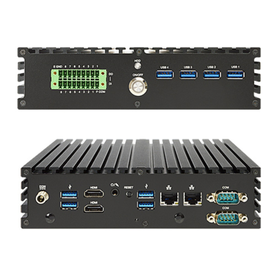
Page 8: Layout Diagram
1* SMBUS header 1* 9-pin USB 2.0 header (Expansible to 2* USB 2.0 port) 1* SPEAK_CON header 1* LAN Status LED header Layout Diagram Rear IO Panel Diagram: RS232 2.5Gbps RJ-45 Serial Ports 12V DC-in LAN Ports HDMI Ports Reset Power... - Page 9 Motherboard Internal Diagram-Front Side 12V DC-in Power Connector CPUFAN1 Connector *DDR3L SODIMM Slot (SODIMM1) USB 3.0 Ports *M.2 Socket 3 Slot PCIE1: Sideway (M2.M) PCI Express x1 Slot HDMI Port Line-Out & MIC Combo Port 5V_DCOUT Connector 3W Amplifier Header Reset Button JATX_AT *SIM Card Slot...
- Page 10 Jumper Jumper Name Description PITCH JMPE1 MPE1 Slot VCC Select 3-pin Block 2.54mm JMPE2 MPE2 Slot VCC Select 3-pin Block 2.54mm JATX_AT ATX/AT Mode Select 3-pin Block 2.54mm Pin (1-2): Clear ME Settings 8-pin Block 2.54mm Pin (3-4): Clear CMOS Pin (5-6): ME Disable Pin (7-8): Case Open Detection Connectors...
-
Page 11: Chapter 2 Hardware Installation
Chapter 2 Hardware Installation 2-1 Jumper Setting JMPE1 (3-pin): MPE1 Slot VCC Select PITCH=2.54mm → JMPE1 MPE1 Slot Power VCC Select MPE1 1-2 Closed: MPE1 Slot Power VCC= 3.3V; JMPE1 2-3 Closed: MPE1 Slot Power VCC= 3.3VSB. JMPE2 (3-pin): MPE2 Slot VCC Select PITCH=2.54mm →... - Page 12 JATX_AT (3-pin): ATX Mode/ AT Mode Select PITCH=2.54mm JATX_AT *ATX Mode Selected: Press power button to power on after power input ready; AT Mode Selected: Directly power on as power input ready. Pin 1&2 of J1 (8-pin): Clear ME Settings ( Clear ME RTC ) PITCH=2.54mm →...
- Page 13 Pin 3&4 of J1 (8-pin): Clear CMOS RAM Settings PITCH=2.54mm Pin 5&6 of J1 (8-pin): ME Disable ( TXE Override Setting ) PITCH=2.54mm → Pin 5&6 of J1 ME Disable Pin1 5-6 Open: Enable Security Measures in the Flash Descriptor(Default); Pin1 5-6 Closed: Disable Security Measures in the Flash Descriptor(Override).
- Page 14 Pin 7&8 of J1 (8-pin): Case Open Detection PITCH=2.54mm Pin (7&8) short: When Case open function pin short to GND, the Case open function was detected. When used, needs to enter BIOS and enable ‘Case Open Detect’ function. In this case if your case is removed, next time when you restart your computer, a message will be displayed on screen to inform you of this.
-
Page 15: Connectors And Headers
Connectors and Headers 2-2-1 Connectors (1) Rear I/O Connectors *Refer to Page-3: Rear IO Panel Diagram. Icon Name Function For user to connect compatible power 12V DC-in Power adapter to provide power supply for the Connector system. To connect USB keyboard, mouse or other devices compatible with USB specification. - Page 16 (2) CPUFAN1 (4-pin): CPUFAN Connector CPUFAN1 Control Fan Speed +12V Fan Power Pin1 (3) SYSFAN1 (4-pin): SYSFAN Connector SYSFAN1...
-
Page 17: Headers
(4) 5V_DCOUT (2-pin): External power supply 5V_DCOUT 2-2-2 Headers (1) JW_FP (9-pin): Front Panel Header PITCH=2.54mm JW_FP... - Page 18 (2) GPIO_CON1 (10-pin): GPIO Header PITCH=2.54mm GPIO_CON1 (3) SMBUS (5-Pin): SMBUS Header PITCH=2.54mm SMBUS 3VSB SMBUS_ALERT SMBUS_DATA SMBUS_CLK Pin1...
- Page 19 (4) FP_USB1 (9-pin): USB 2.54 Header PITCH=2.54mm FP_USB1 (5) JLED (4-pin): LAN Activity LED Header PITCH=2.54mm JLED Pin1...
- Page 20 (6) SPEAK_CON1 (4-pin): Speaker Wafer PITCH=2.0mm Pin No. Definition SPEAK_CON1...
-
Page 21: Chapter 3 Introducing Bios
Chapter 3 Introducing BIOS Notice! The BIOS options in this manual are for reference only. Different configurations may lead to difference in BIOS screen and BIOS screens in manuals are usually the first BIOS version when the board is released and may be different from your purchased motherboard. Users are welcome to download the latest BIOS version form our official website. -
Page 22: Function Keys
Press <Del> to enter Setup/ Press <F7> to enter Popup Menu. BIOS Menu Screen The following diagram show a general BIOS menu screen: Menu Bar General Help Items Current Setting Value Menu Items Function Keys... -
Page 23: Bios Menu Screen
Function Keys In the above BIOS Setup main menu of, you can see several options. We will explain these options step by step in the following pages of this chapter, but let us first see a short description of the function keys you may use here: ... -
Page 24: Main Menu
Advanced To change system advanced configuration Chipset To change chipset configuration Security Password settings Boot To change boot settings Save & Exit Save setting, loading and exit options. User can press the right or left arrow key on the keyboard to switch from menu bar. The selected one is highlighted. -
Page 25: Advanced Menu
System Date Set the date. Please use [Tab] to switch between date elements. System Time Set the time. Please use [Tab] to switch between time elements. 3-7 Advanced Menu OS Selection The optional settings: [Windows]; [Intel Linux]; [MSDOS]. * Note: User need to go to this item to select the OS mode before installing corresponding OS driver, otherwise problems will occur when installing the driver. - Page 26 ► Trusted Computing Press [Enter] to enable or disable ‘Security Device Support’. Configuration Security Device Support Use this item to enable or disable BIOS support for security device, O.S will not show security device. TCG EFI protocol and INT1A interface will not be available. The optional settings: [Disabled];...
- Page 27 ERP Support Use this item to Energy-Related Products function The optional settings: [Disabled]; [Enabled]. This item should be set as [Disabled] if you wish to have all active wake-up functions. Case Open Detect Use this item to detect case has already open or not, show message in POST. The optional settings: [Disabled];...
- Page 28 WatchDog Wake-up Timer Unit The optional settings are: [Sec.]; [Min.]. ATX Power Emulate AT Power This item support Emulate AT power function, MB power On/Off control by power supply. Use needs to select ‘AT or ATX Mode’ on MB jumper at first (refer to AT_MODE jumper setting Pin 1&2 of for ATX Mode &...
- Page 29 The optional settings: [None]; [Even]; [Odd]; [Mark]; [Space]. Even: parity bit is 0 if the data bits is odd; Odd: parity bit is 0 if num of 1’s in the data bits is odd; Mark: parity bit is always 1; Space: Parity bit is always 0; Mark and Space Parity do not allow for error detection.
- Page 30 [VT400]. Redirection After BIOS POST The optional settings are: [Always Enable]; [BootLoader]. Whet Bootloader is selected, then Lagacy Console Redirection is disabled before booting to legacy OS. When Always Enable is selected, then Legacy Console is enabled for legacy OS. Default setting for this option is set to Always Enable.
- Page 31 Flow Control Flow control can prevent data loss from buffer overflow. When sending data, if the receiving buffers are full, a “stop” signal can be sent to stop the data flow. Once the buffers are empty, a “start” signal can be sent to re-start the flow. Hardware flow control uses two wires to send start/stop signals.
- Page 32 CPUFAN/SYSFAN1 Idle-Speed Temperature Use this item to set CPUFAN /SYSFAN idle speed temperature. Fan will run at idle speed when below this pre-set temperature. CPUFAN/SYSFAN Idle-Speed Duty Use this item to set CPUFAN/SYSFAN idle speed duty. Fan will run at idle speed when below this pre-set duty.
- Page 33 7]; [Core C6]; [Core C1]; [Unlimited]. Network Stack Configuration Press [Enter] to go to ‘Network Stack’ screen to make further settings. Network Stack The optional settings are: [Enabled]; [Disabled]. When set as [Enabled], the following sub-items shall appear: Ipv4 PXE Support The optional settings are: [Disabled];...
- Page 34 This item controls the execution of UEFI and Legacy Storage OpROM. The optional settings are: [Do not launch]; [UEFI]; [Legacy]. Video This item controls the execution of UEFI and Legacy Video OpROM. The optional settings are: [UEFI]; [Legacy]. Other PCI devices This item determines OpROM execution policy for devices other than Network, storage or video.
- Page 35 Use this item to 1 to 60 minute(s) USB Wake-up from S4 Use this item to enable or disable USB wakeup from S4. **Note: USB Wake-up is affected by ERP function in S4. Please disable ERP before activating this function in S4. ...
- Page 36 The optional settings: [Auto]; [Manual]. ‘Auto’ uses default value: for a root port it is 100 ms, for a hub port the delay is taken from hub descriptor. Select [Manual] you can set value for the following sub-item: ‘Device Power-up Delay in Seconds’.
-
Page 37: Chipset Menu
3-8 Chipset Menu ► Uncore Configuration Press [Enter] to make settings for the following sub-items: GTT Size The optional settings are: [2MB]; [4MB]; [8MB]. DVMT Pre-Allocated Use this item to select DVMT 5.0 pre-allocated (fixed) graphics memory size used by the internal graphics device. The optional settings are: [64M];... - Page 38 graphics device. The optional settings are: [128M]; [256M]; [MAX]. Primary IGFX Boot Display Use this item to select the video device which will be activated during POST. This has no effect if external graphics present. Secondary boot display selection will appear based on your selection.
- Page 39 The default setting is: [AHCI]. SATA Port SATA Port Use this item to enable or disable each SATA port. The optional settings: [Disabled]; [Enabled]. Use this item to enable or disable M.2 SATA port. The optional settings: [Disabled]; [Enabled]. HD-Audio Support Use this item to enable or disable HD-Audio Support.
-
Page 40: Security Menu
3-9 Security Menu Security menu allow users to change administrator password and user password settings. Administrator Password If there is no password present on system, please press [Enter] to create new administrator password. If password is present on system, please press [Enter] to verify old password then to clear/change password. - Page 41 administrator password. Secure Boot Press [Enter] to make customized secure settings: Secure Boot Control The optional settings are: [Disabled]; [Enabled]. Secure Boot can be enabled if 1. System running in user mode with enrolled Platform Key (PK); 2. CSM function is disabled. Secure Boot Mode The optional settings are: [Standard];...
-
Page 42: Boot Menu
Platform Key (PK)/Key Exchange Keys/Authorized Signature/Forbidden Signature/ Authorized TimeStamps/OS Recovery Signatures Use this item to enroll Factory Defaults or load the keys from a file with: 1. Public Key Certificate in: a) EFI_SIGNATURE_LIST b) EFI_ CERT_X509 (DER encoded) c) EFI_ CERT_RSA2048 (bin) d) EFI_ CERT_SHA256 (bin) 2. -
Page 43: Save & Exit Menu
Bootup Numlock State Use this item to select keyboard numlock state. The optional settings are: [On]; [Off]. Quiet Boot The optional settings are: [Disabled]; [Enabled]. Boot Option Priorities Boot Option #1 Use this item to decide system boot order from available options. 3-11 Save &... - Page 44 Discard Changes and Reset This item allows user to reset the system without saving any changes. Restore Defaults Use this item to restore /load default values for all the setup options. Save as User Defaults Use this item to save the changes done so far as user defaults. Restore User Defaults Use this item to restore defaults to all the setup options.
Need help?
Do you have a question about the JBC390F841VGU and is the answer not in the manual?
Questions and answers