Table of Contents
Advertisement
618AS Pro-R/618AF Pro-R
M/B For Socket 370 Pentium
Trademark:
* Pentium is registered trademark and MMX is a trademark of Intel Corporation,
the other names and brands are the property of their respective owners
* Specifications and Information contained in this documentation are furnished for information use only, and are
subject to change at any time without notice, and should not be construed as a commitment by manufacturer.
618AS Pro/618AF Pro
USER'S MANUAL
NO. G03-618AFP2A
Release date: August 2001
** Year 2000 compliant **
III Processor
Advertisement
Table of Contents

Related Manuals for JETWAY 618AFP2A


Summary of Contents for JETWAY 618AFP2A
- Page 1 618AS Pro-R/618AF Pro-R USER'S MANUAL M/B For Socket 370 Pentium III Processor NO. G03-618AFP2A Release date: August 2001 ** Year 2000 compliant ** Trademark: * Pentium is registered trademark and MMX is a trademark of Intel Corporation, the other names and brands are the property of their respective owners * Specifications and Information contained in this documentation are furnished for information use only, and are subject to change at any time without notice, and should not be construed as a commitment by manufacturer.
-
Page 2: Table Of Contents
TABLE OF CONTENT USER’S NOTICE................ii MANUAL REVISION INFORMATION..........1 THERMAL SOLUTIONS..............1 CHAPTER 1 INTRODUCTION OF MOTHERBOARD 1-1 FEATURE OF MOTHERBOARD ..........2 1-2 SPECIFICATION ..............3 1-3 PERFORMANCE LIST ............4 1-3-1 618AF PRO................1-3-2 618AS PRO ..................... 1-4 LAYOUT DIAGRAM &... -
Page 3: User's Notice
3-9 PNP/PCI CONFIGURATION SETUP .......... 41 3-10 PC HEALTH STATUS............. 42 3-11 MISCELLANEOUS CONTROL ..........43 3-12 LOAD STANDARD/OPTIMIZED DEFAULTS ......44 3-13 SET SUPERVISOR/USER PASSWORD ........44 CHAPTER 4 DRIVER & FREE PROGRAM INSTALLATION MAGIC INSTALL SUPPORTS WINDOWS 95/98/98SE/NT4.0/2000 ..46 4-1 INF ....... -
Page 4: Manual Revision Information
Manual Revision Information Reversion Revision History Date Second Edition August 2001 Item Checklist Motherboard Cable for IDE/Floppy CD for motherboard utilities ¡ ¼ Cable for USB Port 3/4 (Option) Cable for VGA (Only for 618AF Pro/618AF Pro-R) IDE Cable for RAID (Only for 618AS Pro-R/618AF Pro-R) User’s Manual ... -
Page 5: Feature Of Motherboard
Chapter 1 Introduction of 618AS Pro/618AF Pro/618AS Pro-R/618AF Pro-R Motherboard 1-1 Feature of motherboard The motherboard is design for use Intel’s new generation Pentium III /Tualatin processors, which utilize the Socket 370 design and the memory size expandable to 512MB. This motherboard use the newest Intel chipset, whose 133MHz front side bus &... -
Page 6: Specification
1-2 Specification Spec Description ∗ ATX form factor 4 layers PCB size: 30.5x24.4cm Design ∗ Intel 815E B-Step Chipset for 618AF Pro/618AF Pro-R Chipset ∗ Intel 815EP B-Step chipset for 618AS Pro/618AS Pro-R ∗ Support Pentium CPU Socket III 500∼1GHz processor ∗... -
Page 7: Performance List
1-3 Performance List 1-3-1 618AF Pro The following performance data list is the testing result of some popular benchmark testing programs. These data are just referred by users, and there is no responsibility for different testing data values gotten by users (the different Hardware & Software configuration will result in different benchmark testing results.) ... -
Page 8: 618As Pro
1-3-2 618AS Pro The following performance data list is the testing result of some popular benchmark testing programs. These data are just referred by users, and there is no responsibility for different testing data values gotten by users (the different Hardware & Software configuration will result in different benchmark testing results.) ... -
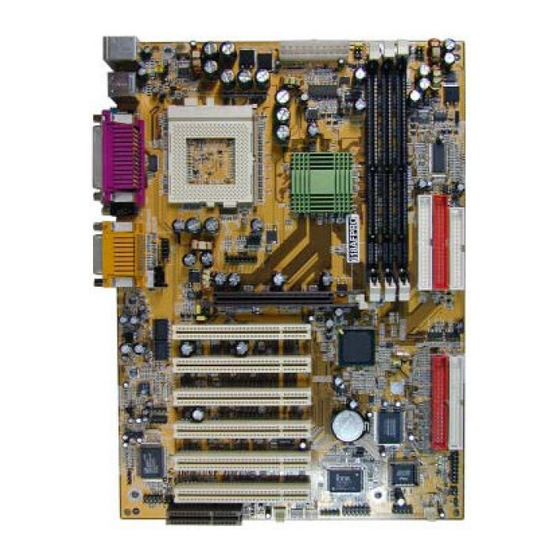
Page 9: Layout Diagram & Jumper Setting
1-4 Layout Diagram & Jumper Setting PRINT GAME/MIDI PORT PS/2 MOUSE PS/2 Keyboard LINE-IN COM1 COM2 LINE-OUT FAN1 ATX Power K/B Power ON Connector Jumper (JK1) PS2 KB/Mouse Port CPU F.S.B. Clock Select Jumper (SW1, USB Port SW2, SW3, SW4) 370 CPU Socket PC99 Back Panel DIMM Socket X3... -
Page 10: Expansion Sockets
Jumpers Jumper Name Description Page JS3, JS4 CPU & SDRAM Frequency Setting 3-pin Block JS1, JS2 2-pin Block Keyboard Power ON Function Setting 3-pin Block JBAT CMOS RAM Clear 3-pin Block Onboard Audio CODEC Setting 3-pin Block p.10 ATA100/RAID Mode Setting 3-pin Block p.10 Connectors... -
Page 11: Hardware Installation Steps
Chapter 2 Hardware installation 2-1 Hardware installation Steps Before using your computer, you had better complete the following steps: 1. Check motherboard setting 2. Install CPU 3. Install Memory 4. Install Expansion cards 5. Connect Ribbon cables, Panel wires, and power supply 6. - Page 12 2. Keyboard Power On Function setting (3-pin) : JK1 This allows you to disable the keyboard power on function. Set the jumper to enabled or disabled if you wish to use your keyboard (by pressing < >) to power on your computer, this feature requires an ATX power supply that can supply at least 300mA on the +5VSB lead.
- Page 13 4. Onboard Audio CODEC Setting (3-pin) : JA1 The onboard audio CODEC can be master or slave mode. This jumper’s default is to be master mode (2-3) close, when you use a AMR adapter please check, if the AMR is set to master mode then on board audio CODEC must be set to be slave mode.
-
Page 14: Install Cpu
2-3 Install CPU 2-3-1 Glossary Chipset (core logic) - two or more integrated circuits which control the interfaces between the system processor, RAM, I/O devises, and adapter cards. Processor socket - the socket used to mount the system processor on the motherboard. Slot (AGP, PCI, ISA, RAM) - the slots used to mount adapter cards and system RAM. -
Page 15: Setting Cpu Bus Clock & Memory Clock Jumper
RB 80526 P2 866 256 RB : FC–PGA packing : P2–133MHz front side bus frequency PY–100MHz front side bus frequency 866 : CPU internal frequency, where here is 866MHz 256 : the size of L2 cache, where here is 256K Celeron FC–PGA On the surface of the CPU as shown on the right picture, under the word of “Celeron”... -
Page 16: Install Cpu
2-3-3 Install CPU This motherboard provides a ZIF socket 370. The CPU that comes with the motherboard should have a cooling FAN attached to prevent overheating. If this is not the case, then purchase a correct cooling FAN before you turn on your system. WARNING! Be sure that there is sufficient air circulation across the processor’s heatsink and CPU cooling FAN is working correctly, otherwise it may... - Page 17 You can choose the situation you want to try. CPU/SDRAM (MHz) AUTO 66/100 (Default) 100/100 133/100 133/133 CMOS Setup Utility – Copyright(C) 1984-2001 Award Software Miscellaneous Control CyrixIII Clock Ratio Default Item Help Auto Detect DIMM/PCI Clk Enabled Spread Spectrum Disabled ** Current Host Clock is 66Mhz ** Menu Level >...
-
Page 18: Install Memory
2-4 Install Memory This motherboard provides three 168-pin DUAL INLINE MEMORY MODULES (DIMM) sites for memory expansion available from minimum memory size of 32MB to maximum memory size of 512MB SDRAM. Valid Memory Configurations DIMM DIMM1 DIMM2 DIMM3 SDRAM Clock 100MHz 133MHz According the specification when SDRAM clock is 133MHz only can support 2 pcs... -
Page 19: Expansion Cards
2-5 Expansion Cards WARNING! Turn off your power when adding or removing expansion cards or other system components. Failure to do so may cause severe damage to both your motherboard and expansion cards. 2-5-1 Procedure For Expansion Card Installation 1. Read the documentation for your expansion card and make any necessary hardware or software setting for your expansion card such as jumpers. -
Page 20: Interrupt Request Table For This Motherboard
2-5-3 Interrupt Request Table For This Motherboard Interrupt request are shared as shown the table below: INT A INT B INT C INT D INT E INT F INT G INT H √ Slot 1 √ Slot 2 √ Slot 3 √... -
Page 21: Connectors, Headers
2-6 Connectors, Headers 2-6-1 Connectors Power Connector (20-pin block) : ATXPWR ATX Power Supply connector. This is a new defined 20-pin connector that usually comes with ATX case. The ATX Power Supply allows to use soft power on momentary switch that connect from the front panel switch to 2-pins Power On jumper pole on the motherboard. - Page 22 (6) Serial Port COM1: COM1/COM2 COM1 is the 9-pin D-Subminiature mail connector. The On-board serial port can be disabled through BIOS SETUP. Please refer to Chapter 3 “INTEGRATED PERIPHERALS SETUP“ section for more detail information. PS/2 MOUSE PRINT GAME/MIDI PORT PS/2 Keyboard USB1 COM1 COM2...
-
Page 23: Headers
IDE2 IDE1 Pin 1 Pin 1 Secondary IDE Connector Primary IDE Connector • Two hard disks can be connected to each connector. The first HDD is referred to as the “Master” and the second HDD is referred to as the “Slave”. •... - Page 24 VGA Port Headers USB Port Headers (9-pin) : USB _ B These headers are used for connecting the additional USB port plug. By attaching an option USB cable, your can be provided with two additional USB plugs affixed to the back panel.
- Page 25 Power LED: PWR LED The Power LED is light on while the system power is on. Connect the Power LED from the system case to this pin. Power switch: PWR BTN This 2-pin connector connects to the case-mounted power switch to power ON/OFF the system.
- Page 26 These connectors support cooling fans of 350mA (4.2 Watts) or less, depending on the fan manufacturer, the wire and plug may be different. The red wire should be positive, while the black should be ground. Connect the fan’s plug to the board taking into consideration the polarity of connector.
- Page 27 This header connect to Front Panel Line-In, Line-out, MIC connector with cable. AUDIO L-OUT-L L-OUT-R MICP L-IN-R L-IN-L Pin 1 Audio Front Panel Headers (16) CD Audio-In Headers (4-pin) : CDIN1,CDIN2 CDIN1 and CDIN2 are the connectors for CD-Audio Input signal. Please connect it to CD-ROM CD-Audio output connector.
-
Page 28: Starting Up Your Computer
1. After all connections are made, close your computer case cover. 2. Be sure all the switch are off, and check that the power supply input voltage is set to proper position, usually in-put voltage is 220V∼240V or 110V∼120V depending on your country’s voltage used. -
Page 29: Chapter 3 Introducing Bios
Chapter 3 Introducing BIOS The BIOS is a program located on a Flash Memory on the motherboard. This program is a bridge between motherboard and operating system. When you start the computer, the BIOS program gain control. The BIOS first operates an auto-diagnostic test called POST (power on self test) for all the necessary hardware, it detects the entire hardware device and configures the parameters of the hardware synchronization. -
Page 30: Getting Help
3-2 Getting Help Main Menu The on-line description of the highlighted setup function is displayed at the bottom of the screen. Status Page Setup Menu/Option Page Setup Menu Press F1 to pop up a small help window that describes the appropriate keys to use and the possible selections for the highlighted item. - Page 31 Integrated Peripherals Use this menu to specify your settings for integrated peripherals. Power Management Setup Use this menu to specify your settings for power management. PnP/PCI configurations This entry appears if your system supports PnP/PCI. PC Health Status This entry shows your PC health status. Miscellaneous Control Use this menu to specify your settings for Miscellaneous Control.
-
Page 32: Standard Cmos Features
3-4 Standard CMOS Features The items in Standard CMOS Setup Menu are divided into several categories. Each category includes no, one or more than one setup items. Use the arrow keys to highlight the item and then use the <PgUp> or <PgDn> keys to select the value you want in each item. -
Page 33: Advanced Bios Features
If the controller of HDD interface is SCSI, the selection shall be “None”. If the controller of HDD interface is CD-ROM, the selection shall be “None” Access Mode The settings are Auto Normal, Large, and LBA. Cylinder number of cylinders Head number of heads Precomp... - Page 34 Enabled Activates automatically when the system boots up causing a warning message to appear when anything attempts to access the boot sector of hard disk partition table. CPU L1 Cache The default value is Enabled. Enabled (default) Enable cache Disabled Disable cache Note: The L1 cache is built in the processor.
-
Page 35: Advanced Chipset Features
Fast (default) The A20 signal is controlled by port 92 or chipset specific method. Typematic Rate Setting Keystrokes repeat at a rate determined by the keyboard controller. When enabled, the typematic rate and typematic delay can be selected. The settings are: Enabled/Disabled. Typematic Rate (Chars/Sec) Sets the number of times a second to repeat a keystroke when you hold the key down. - Page 36 ¡ ü ¡ ý ¡ ú ¡ û Move Enter:Select +/-/PU/PD:Value F10:Save ESC:Exit F1:General Help F5:Previous Values F6:Optimized Defaults F7:Standard Defaults Note: Change these settings only if you are familiar with the chipset. SDRAM Timing Setting Please refer to section 3-6-1 System BIOS Cacheable Selecting Enabled allows caching of the system BIOS ROM at F0000h-FFFFFh, resulting in better system performance.
-
Page 37: Sdram Timing Setting
reside in a graphics aperture. The aperture range should be programmed as not cacheable in the processor cache, accesses with the aperture range are forwarded to the main memory, then PAC will translate the original issued address via a translation table that is maintained on the main memory. -
Page 38: Integrated Peripherals
If an insufficient number of cycles is allowed for the RAS to accumulate its charge before DRAM refresh, the refresh may be incomplete and the DRAM may fail to retain date. Fast gives faster performance; and Slow gives more stable performance. This field applies only when synchronous DRAM is installed in the system. -
Page 39: On-Chip Ide Function
Power After PWR-Fail This option will determine how the system will power on after a power failure. 3-7-1 On-Chip IDE Function CMOS Setup Utility – Copyright(C) 1984-2001 Award Software On-Chip IDE Function On-Chip Primary PCI IDE Enabled Item Help On-Chip Secondary PCI IDE Enabled IDE Primary Master Auto... -
Page 40: On-Chip Sio Function
Block mode is also called block transfer, multiple commands, or multiple sector read/write. If your IDE hard drive supports block mode (most new drives do), select Enabled for automatic detection of the optimal number of block read/writes per sector the drive can support. -
Page 41: On-Chip Device Function
Parallel Port Mode : Standard Parallel Port : Enhanced Parallel Port : Extended Capability Port SPP/EPP/ECP/ECP+EPP To operate the onboard parallel port as Standard Parallel Port only, choose “SPP.” To operate the onboard parallel port in the EPP modes simultaneously, choose “EPP.” By choosing “ECP”, the onboard parallel port will operate in ECP mode only. -
Page 42: Power Management Setup
AC97 Modem This item allows you to decide to enable/disable the 815 chipset family to support AC97 Modem. The settings are: Enabled, Disabled. Game Port Address/Midi Port Address This will determine which Address the Game Port/Midi Port will use. 3-8 Power Management Setup The Power Management Setup allows you to configure your system to most effectively save energy saving while operating in a manner consistent with your own style of computer use. - Page 43 Video Off Method This determines the manner in which the monitor is blanked. V/H SYNC+Blank This selection will cause the system to turn off the vertical and horizontal synchronization ports and write blanks to the video buffer. Blank Screen This option only writes blanks to the video buffer. DPMS (default) Initial display power management signaling.
-
Page 44: Pnp/Pci Configuration Setup
You can choose what hour, minute and second the system will boot up. Note: If you have change the setting, you must let the system boot up until it goes to the operating system, before this function will work. PM Timer Reload Events Pm Timer Reload events are I/O events whose occurrence can prevent the system from entering a power saving mode or can awaken the system from such a mode. -
Page 45: Pc Health Status
The settings are: Enabled and Disabled. Resource Controlled By The Award Plug and Play BIOS has the capacity to automatically configure all of the boot and Plug and Play compatible devices. However, this capability means absolutely nothing unless you are using a Plug and Play operating system such as Windows 95/98. -
Page 46: Shutdown Temperature
This will show the CPU/FAN/System voltage chart and FAN Speed. Shutdown Temperature This option is for setting the Shutdown temperature level for the processor. When the processor reaches the temperature you set, this will shutdown the system. 3-11 Miscellaneous Control This section is for setting CPU Miscellaneous Control. -
Page 47: Load Standard/Optimized Defaults
AGP VCC3 This item allows you to select 3.3V of the AGP VGA card. The choice are : 3.30V(Default), 3.11V, 3.21V, 3.27V, 3.36V, 3.41V, 3.48V, 3.58V. AGP VDDQ Select This item allows you to select 1.5V of the AGP VGA card. The choice are : 1.5V(Default), 1.6V, 1.7V. - Page 48 also press <Esc> to abort the selection and not enter a password. To disable a password, just press <Enter> when you are prompted to enter the password. A message will confirm that the password will be disabled. Once the password is disabled, the system will boot and you can enter Setup freely.
-
Page 49: Chapter 4 Driver & Free Program Installation
Chapter 4 DRIVER & FREE PROGRAM INSTALLATION Check your package and there is A MAGIC INSTALL CD included. This CD consists of all DRIVERS you need and some free application programs and utility programs. In addition, this CD also include an auto detect software which can tell you which hardware is installed, and which DRIVERS needed so that your system can function properly. -
Page 50: Inf Install Intel 815 Chipset System Driver
From MAGIC INSTALL MENU you may make 12 selections: 1. INF install INTEL 815 chipset system driver 2. IDE install Intel Ultra ATA Storage driver 3. VGA install on-board VGA driver (618AF Pro/618AF Pro-R Only) 4. SOUND install AC97 sound driver and the program for editing/playback 5. -
Page 51: Ide Install Intel Ultra Ata Storage Driver
3. This chart shows motherboards supported 4. Select if you want computer re-started by the driver click NEXT click Finish NOTE: MAGIC INSTALL will auto detect file path X:\INTEL815\INF\INFINST.EXE This driver supports WINDOWS 95/98/98SE/ME/2000 (NT4.0 do not require) 4-2 IDE install Intel ULTRA ATA Storage driver 1. -
Page 52: Vga Install On-Board Vga Driver
5. Select if you want to re-start your computer 6. You may choose to remove the driver or you and click Finish may remove it at ADD/REMOVE PROGRAMS NOTE: MAGIC INSTALL will auto detect file path X:\INTEL815\IDE\SETUP.EXE This driver supports WINDOWS 95/98/98SE/ME/NT4.0/2000 4-3 VGA install on-board VGA driver (618AF Pro/618AF Pro-R Only) A. -
Page 53: Ac97 Sound Driver And The Program Install For Editing/Playback
NOTE: The path of the file for WIN95 is X:\INTEL815\VGA\WIN95\SETUP.EXE for WIN98\WIN98SE and ME is X:\INTEL815\VGA\WIN9X\SETUP.EXE for NT4.0 is X:\INTEL815\VGA\NT40\SETUP.EXE for Windows 2000 is X:\INTEL815\VGA\WIN2K\SETUP.EXE 4-4 AC97 sound driver and the program Install for editing/playback 1. Click SOUND when MAGIC INSTALL 2. -
Page 54: Install Promise Ata100/Raid Driver
4-5 Install PROMISE ATA100/RAID Driver (Only for 618AS Pro-R/ 618AF Pro-R) (Read CD-PACK X:\MANUAL\PROMISE.DOC to get more information) 4-5-1 Install PROMISE ATA100 IDE Controller Driver When the Jumper setting ATA100 you will have next screen in Magic Install MENU. Click PROMISE ATA100 Controller Install PROMISE ATA100 Controller Driver in MAGIC INSTALL MENU Driver... -
Page 55: Install Promise Ide Raid Controller Driver
4-5-2 Install PROMISE IDE RAID Controller Driver (Only for 618AS Pro-R/618AF Pro-R) When the Jumper setting in RAID Mode you will have next screen in Magic Install MENU. Click PROMISE RAID Controller Install PROMISE RAID Controller Driver when MAGIC INSTALL Driver MENU Click Yes to Restart your computer... -
Page 56: Install Promise Ide Raid Controller Utility
4-5-3 Install PROMISE IDE RAID Controller Utility (Only for 618AS Pro-R/618AF Pro-R) Click PROMISE RAID Controller In this screen please click Next to install Utility in MAGIC INSTALL MENU PROMISE Monitoring Utility Click Next to continue Setup PROMISE Select the components you want to FastTrak Controller Utility install and click Next to Setup Select Yes if you want the FastCheck... -
Page 57: Pc-Health Installs Smart Guardian Software For Hardware Monitoring Device
After Windows restart click FastCheck Monitoring Utility you can monitor the RAID Status For detail information please read PROMISE.DOC in CD-PACK X:\MANUAL\PROMISE.DOC 4-6 PC-HEALTH installs SMART GUARDIAN software for hardware monitoring device 1. Click PC-HEALTH when MAGIC 2. Click OK when SMART GUARDIAN INSTALL MENU appears INSTALL appears 3. -
Page 58: Magic Bios Install Bios Live Update Utility
4-7 MAGIC BIOS Install BIOS Live Update Utility Click Magic BIOS when Magic Install Click Next to install the Magic BIOS in MENU appears Destination Folder After finish Setup you will have a Magic Double click the Magic BIOS icon you will BIOS icon in your screen have this picture, choose from internet you can upgrade BIOS On-line... - Page 59 Click Yes if you want to update the BIOS When System programming BIOS don’t turn otherwise choose No to exit off power, after finish update BIOS, the system will clear CMOS and automatically Restart When choose From Local Driver to update 10.
-
Page 60: Pc-Cillin Install Pc-Cillin 2000 Anti-Virus Program
4-8 PC-CILLIN Install PC-CILLIN 2000 Anti-virus program 1. Click PC-CILLIN when MAGIC 2. Click NEXT when PC-CILIN 2000 INSTALL MENU Appears SETUP APPEARS. Then click YES when the announcement of copywrite appears. Software is starting to detect HD for virus 3. - Page 61 7. If you want to make a rescue disc, insert 8. Setup Complete and click Finish a 1.44 MB disc 9. Enter Your name and E-mail address 10. After install PC-cillin 2000 complete we Register PC-cillin 2000 or Click Cancel recommend select update item to Register Later download newest virus code and setting...
-
Page 62: How To Disable On-Board Sound
4-9 HOW TO DISABLE ON-BOARD SOUND Enter BIOS SETUP choose INTEGRATE PERIPHERALS choose ON-CHIP DEVICE FUNCTION choose AC97 AUDIO Disable on-board sound function by press PAGE DOWN KEY to Disable 4-10 HOW TO UPDATE BIOS Before update BIOS please choose Disabled in “Flash Part Write Protect” item on “Miscellaneous Control”...
Need help?
Do you have a question about the 618AFP2A and is the answer not in the manual?
Questions and answers